
Biomechanics of Spinal Deformities
For progressive deformities, the spine is subjected to some form of “pathological” stress. Spinal surgeons need to understand the source of this “pathological” stress that causes the deformity. Only when these “pathological” stresses are counteracted and neutralized can the goals of correcting scoliosis, preventing deformity progression, and restoring sagittal and coronal balance be achieved.
1. Physical Principles of Spinal Deformities
The forces acting on the spine can be decomposed into different vectors (vectors are defined as forces with fixed and clear directions in three-dimensional space). Forces can act on levers to produce moments, where the distance from the lever’s axis to the point of force application is the moment arm. When a moment acts on a point in space, it causes rotation around an axis or a tendency to rotate around that axis. This axis is known as the instantaneous axis of rotation (IAR). The IAR serves as a pivotal point around which buckling or stretching occurs. The moment is a lever that extends from the IAR to the point of force application on the spine (Figure 1). The moment (M) is defined as the product of the force (F) applied to the lever arm and the length of the lever arm (D), expressed as: M=F×D. The moment is essentially the torque applied by the circumferential force. The magnitude of the circumferential force is the torque.
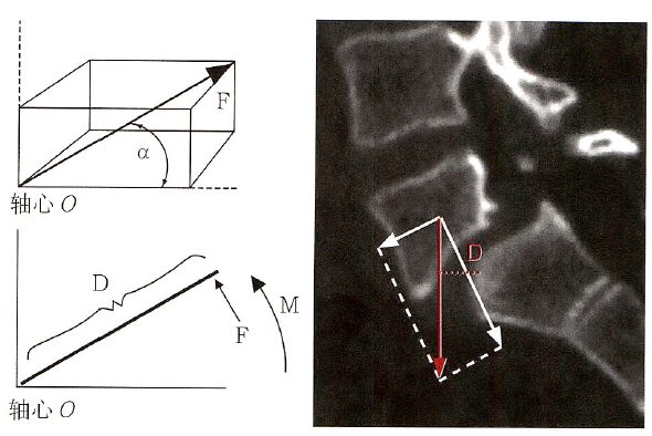
Figure 1: The vector of forces in three-dimensional space. If the force (F) rotates around an axis O in a certain direction, it will generate a moment (M), where M=FxD. Here, D represents the distance from the force to the axis. A typical example is L5/S1 spondylolisthesis, where the L5 vertebra loses its anatomical connection with the posterior bony structures due to the rupture of the vertebral arch and gradually slides forward under the influence of gravity. The gravitational force acting on the L5 vertebra (red arrow) causes it to rotate forward around the dome of the S1 vertebra. The larger the distance of the gravitational line from the dome of S1 (red dashed line, D), the greater the moment acting on the L5 vertebra, making it more likely to rotate or slide forward.
Translation or rotation can occur along any of the three axes in the Cartesian coordinate system (Figure 2). Thus, the spine can undergo six basic segmental movements around the IAR or along the IAR: ① rotation or translation around the long axis; ② rotation or translation around the coronal axis; ③ rotation or translation around the sagittal axis; ④ translation along the spine’s long axis; ⑤ translation along the coronal axis; ⑥ translation along the sagittal axis. Each movement can lead to deformation in one of the two directions involving one or more segments of the spine due to short-term or long-term applied loads.
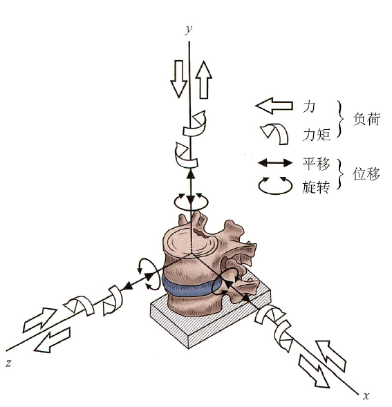
Figure 2: The vertebrae can be divided into three axes in three-dimensional space. The x-axis represents the coronal axis, the y-axis represents the vertical axis, and the z-axis represents the sagittal axis. Under the influence of external forces, the vertebrae can rotate or translate around these three axes.
2. Rotational and Translational Deformations are Important Changes in Spinal Deformities
Due to the six degrees of freedom of the vertebrae, under the influence of “pathological stress,” normal vertebrae gradually exhibit rotational and translational deformations in the coronal, sagittal, and axial planes, leading to changes in adjacent vertebral sequences and exacerbating spinal deformities.
Shear, compression, or tension between adjacent vertebrae can lead to translational deformations, which occur along the axis of the force vector and can happen in any plane. Translational deformations caused by compression are most commonly seen in burst fractures of the vertebrae, which result from the relative compression of the upper and lower endplates of the vertebra. Translational deformations in the same plane can result from opposing vectors of two parallel but non-coinciding forces, causing shear forces between the vertebrae, leading to dislocation or deformity. Tension deformations in the vertical direction are not commonly seen in the formation of spinal deformities. The distracting forces in orthopedics represent vertical tension deformations, which can be produced by spinal traction (like traction) or implanted devices. Most translational deformations in spinal deformities result from one or more types of shear, compression, or tension.
Rotational deformation refers to the influence of moments through the application of centrifugal forces on spinal segments, causing the vertebrae to deviate from the IAR. After a moment is applied to the spine, it may rotate along one or two axes, resulting in angular deformities. These angular deformities can manifest as kyphosis (flexion rotation), lordosis (extension rotation), scoliosis (lateral bending rotation), or combinations of the above. Rotational deformation is the manifestation of asymmetric moments or rotational moments applied to the spinal segments. Rotational deformations around the axial axis (coronal or sagittal axis) can occur at the level of the vertebrae or intervertebral disc, leading to either lordosis or kyphosis and lateral bending. The occurrence of rotational deformation in the spine can also occur around the long axis of the spine, causing the vertebrae to rotate in the horizontal plane. It is important to note that applying rotational stress to the spine can lead to opposite rotational deformations in the vertebrae above and below the unstable segment, which may be radiologically represented as rotational subluxation (Figure 3) and kyphotic deformity at the apex of this unstable segment, resulting in a “stepped” appearance of the spinal canal that can cause neurological damage.
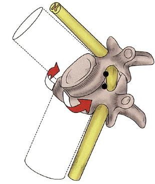
Figure 3: Rotational Subluxation
The persistent presence of “pathological” stresses acting on the spine or normal stresses acting on a deformed spine are necessary conditions for the occurrence or progression of deformities. Deformities are often multi-segmental, and deformities occurring along or around one axis of the Cartesian coordinate system typically produce another movement along or around another axis (i.e., coupling phenomenon). Therefore, when attempting to correct spinal deformities, many factors such as rotation and lateral bending must be taken into account.
The Cobb angle of scoliosis is determined by the inclination of the end vertebrae on the convex and concave sides. The end vertebrae act as a transition zone between the two curves in the coronal plane. Generally, the larger the Cobb angle, the faster the progression of the deformity, as the biomechanical principle behind this is that an increase in Cobb angle increases the moment arm of the force acting on the apex vertebra (Figure 4, red line D), leading to an increase in the moment at the apex vertebra. However, assessing scoliosis solely by the Cobb angle has its limitations; the same Cobb angle can correspond to different curve types, with some scoliosis presenting as a circular arc (like AIS) and others as angular (like NF1 with scoliosis). In this case, the moment arm of the apex vertebra in angular scoliosis is greater than that in circular scoliosis, indicating that the apex vertebra in angular scoliosis experiences a greater moment than that in circular scoliosis, making angular scoliosis more prone to coronal deformity progression. The degree of angular or circular scoliosis can be assessed using the angular ratio parameter, where angular ratio = Cobb angle / number of segments crossed by the scoliosis. A larger angular ratio indicates a more pronounced angular scoliosis and a greater likelihood of progression, thus increasing the risk of neurological complications during surgery.
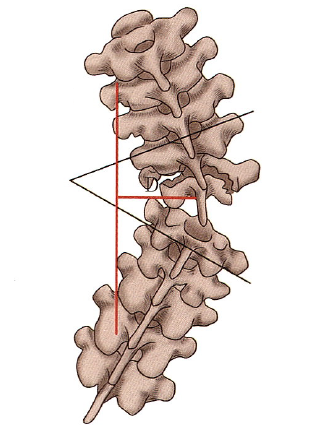
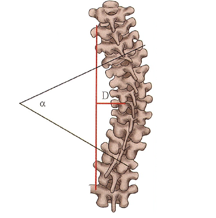
Figure 4: Angular Scoliosis and Circular Scoliosis
It is worth noting that the moment arm acting on the apex vertebra and the distance of the apex vertebra’s offset on X-ray (AVT) are not entirely the same. Currently, there is no clear definition of the moment arm of the apex vertebra in clinical practice. Biomechanically, it should refer to the distance from the line connecting the upper and lower end vertebrae to the apex vertebra, while AVT refers to the distance from the C7 plumb line to the apex vertebra of the thoracic curve (or from the sacral midline to the apex vertebra of the lumbar curve). For simplification and ease of understanding in clinical work, AVT can be approximated as the moment arm of the apex vertebra.
As long as there is curvature of the spine (main curve, compensatory curve, sagittal curvature, etc.), there will be an apex vertebra and end vertebrae. Generally, the intervertebral discs above and below the apex vertebra have the largest angle, while the intervertebral discs above or below the end vertebrae have the smallest angle or no angle. Spinal fixation should not terminate at the apex vertebra of the main curve because if a long moment arm terminates at the apex vertebra, then the apex vertebra will become the IAR of a long moment arm, leading to new rotational deformations around the apex vertebra along different axes, thus forming new deformities.
The compressive load between the endplates of the vertebrae is transmitted through the intervertebral discs, and excessive compression can lead to intervertebral disc degeneration. When subjected to bending or twisting, the biomechanics of the intervertebral discs change. When bending forces are applied during flexion and lateral bending movements, the intervertebral discs exhibit stretching on the convex side and compression on the concave side. Therefore, anterior correction of scoliosis requires the removal of intervertebral discs, not only to relieve the spine and enhance the corrective effect but also to provide strong support against flexion and lateral bending movements during fusion.
The torsional stiffness of the spine is primarily determined by the orientation of the facet joint surfaces, which dictates the degree of rotation of the spine. The facet joints can restrict the degrees of freedom of spinal movement. The small joints of the thoracic and lumbar vertebrae differ in their structure; the facet joints of the thoracic vertebrae are oriented toward the coronal plane, allowing for lateral bending and rotation, while the facet joints of the lumbar vertebrae are oriented toward the sagittal plane, allowing for flexion and extension. The largest directional changes occur at the thoracolumbar junction, where the facet joint orientation also leads to coupled motions. Coupling refers to the simultaneous occurrence of two or more independent movements (e.g., lateral bending and rotation). Spinal scoliosis is a manifestation of this coupling motion.
3. Biomechanics in Spinal Deformity Surgery
Complex deformities can be corrected through the corrective forces generated by spinal implants, which can achieve correction along one or three axes of the Cartesian coordinate system. The corrective forces can align the deformed spine with the line of force of the implants. With the development of posterior internal fixation techniques, current orthopedic techniques generally rely on posterior internal fixation. Orthopedic techniques, especially for adolescent idiopathic scoliosis, generally include translational techniques, distraction and compression techniques, derotation techniques, and posterior coplanar techniques. These techniques can generate corrective forces and moments in three planes (coronal, sagittal, axial) during surgery. Sometimes, a combination of several methods may be used to achieve the best corrective effect. In the coronal plane, corrective forces and moments can be generated for left-right translation, while in the sagittal plane, corrective forces and moments can be generated for anterior-posterior translation, and in the axial plane, tensile forces and rotational moments can be generated along the long axis (Figure 5).
From a purely coronal perspective, the corrective forces for scoliosis mainly include longitudinal and lateral corrective forces. The longitudinal corrective force applies tension to the spine above and below the convexity, causing the spine to straighten, while the lateral corrective force can be understood as applying lateral thrust to the apex vertebra. Ultimately, the ability to correct scoliosis depends on the moments generated by the longitudinal and lateral corrective forces acting on the intervertebral discs.
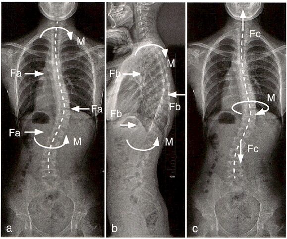
Figure 5: Schematic representation of possible corrective forces in spinal surgery. The lateral push (pull) force Fa in the coronal plane can generate a corrective moment M(a) around the coronal axis, while the push (pull) force Fb in the sagittal plane can generate a corrective moment M(b) around the sagittal axis. The tensile force Fc along the vertical axis can generate a corrective moment M(c) around the vertical axis.
Longitudinal corrective forces can occur in Milwaukee braces, Halo-gravity traction, or intraoperative distraction correction. As shown in Figure 6, longitudinal corrective forces are applied at the upper and lower ends of the convexity (A and B), while at the apex vertebra, the moment applied to the vertebra/intervertebral disc is the force acting on the apex vertebra multiplied by the distance from the apex vertebra to the midline (D in Figure 6, i.e., apical vertebral translation, AVT). Therefore, the more severe the deformity, the larger the AVT, and the greater the moment of the corrective force, the better the distracting force’s corrective effect (Figure 6b). During the correction process, as AVT decreases, the corrective effect of the longitudinal corrective force gradually diminishes (Figure 6c).
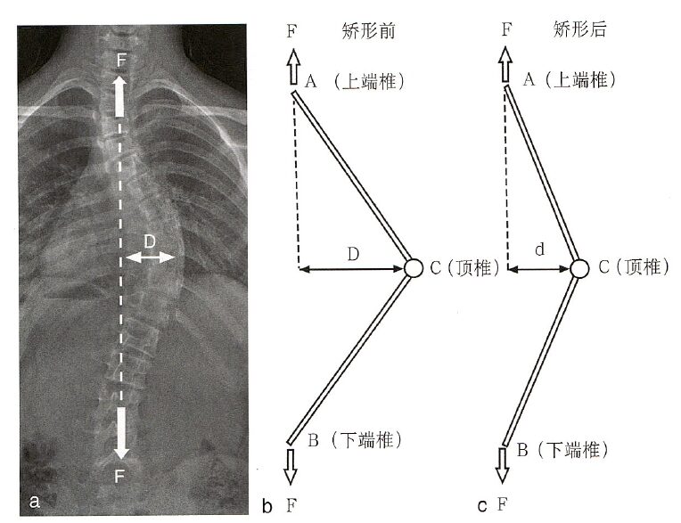
Figure 6: When only longitudinal corrective forces are present, the moment acting on the vertebra/intervertebral disc C at the apex vertebra is the corrective moment Ma=FxD, where D represents the distance from the apex vertebra to the midline, clinically equivalent to AVT (D in a). During the correction process, as D decreases, the corrective moment decreases from FxD to Fxd (b, c).
The lateral corrective force is mainly applied in TLSO braces and translational correction techniques. As shown in Figure 7, the apex vertebra C experiences lateral corrective forces, while the upper and lower ends of the convexity (A and B) experience reaction forces that are half of the corrective force. By decomposing the spinal scoliosis into upper and lower parts, the corrective force acting at the intervertebral disc C at the apex vertebra can be considered as a rotation around A or B, and its moment can be considered as half of the corrective force multiplied by the moment arm (the perpendicular distance from the apex vertebra to the upper or lower end of the convexity, D). Therefore, the more severe the scoliosis or the larger the AVT, the smaller the distance D between the apex vertebra and the end vertebrae, resulting in a smaller moment of the corrective force. This helps explain why brace treatment for severe scoliosis is often ineffective.
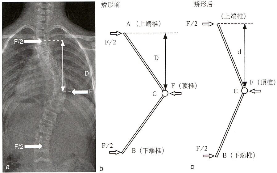
Figure 7: When only lateral corrective forces are present, the moment acting on the vertebra/intervertebral disc C at the apex vertebra is Mt=0.5FxD, where D represents the distance from the apex vertebra to the upper and lower ends. The more severe the spinal deformity, the shorter the distance from the end vertebra to the apex vertebra, i.e., the smaller D (a). During the correction process, as D increases, the corrective moment also gradually increases (b, c).
From the above analysis, it can be seen that the optimal means of correcting scoliosis is the simultaneous presence of both longitudinal and lateral corrective forces. Since the longitudinal corrective force is more effective when scoliosis is severe, initially, longitudinal distracting forces can be prioritized. As the deformity decreases, lateral translational corrective forces can be increased. Figure 8 presents the analysis of forces acting on the intervertebral disc at the apex vertebra when both types of corrective forces are present.
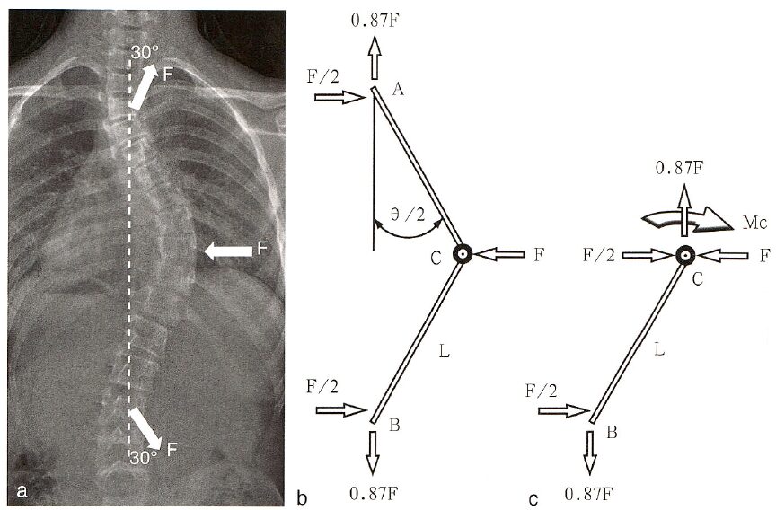
Figure 8: When both longitudinal and lateral corrective forces are present, and both forces are F, assuming the longitudinal tensile force forms an angle of 30° with the midline, the corrective moment at the apex vertebra C is Mc=Ma+Mt, where Ma=0.87Fx Da, and Mt=0.5Fx Dt. Da is the AVT, and Dt is the distance from C to A or B.
Augustus A. White III, in his book Clinical Biomechanics of the Spine, further illustrates the changes in the moment generated at the apex vertebra under the given longitudinal and lateral corrective forces (Figure 3-1-17), where the horizontal axis represents the severity of scoliosis (Cobb angle) and the vertical axis represents the relative corrective moment (the larger the moment, the stronger the corrective ability). The intersection of the relative corrective moments provided by the longitudinal and lateral corrective forces corresponds to a Cobb angle of 53°. Therefore, they propose that when the scoliosis exceeds 53°, priority should be given to using corrective schemes providing longitudinal corrective forces, while when it is less than 53°, priority should be given to schemes providing lateral corrective forces. Of course, the optimal scheme is one that can provide both longitudinal and lateral corrective forces.
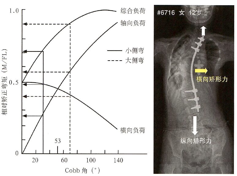
Figure 9: As the Cobb angle increases (horizontal axis), the relative corrective moments provided by lateral and longitudinal corrective forces (vertical axis) also change. The larger the Cobb angle, the smaller the moment from the lateral corrective force and the larger the moment from the longitudinal corrective force. The intersection of the two corresponds to a Cobb angle of 53°, indicating that when the Cobb angle exceeds 53°, longitudinal corrective forces are recommended from a biomechanical perspective.
Source: Pediatric Spinal Surgery


END
Scan to Follow Us