Part One: Introduction
With the advancement of technology and the rise of DIY culture, creating a custom matrix screen enclosure has become an interesting and challenging project. This article will document the entire process of designing an enclosure based on the WS2812B matrix screen, exporting a 3D model of the PCB via the JLCPCB platform, using SolidWorks for enclosure design, and completing the enclosure fabrication through 3D printing. These matrix screens can be used not only for information display but also as decorative or artistic displays. Additionally, after designing a matrix screen for a robot, I realized that without a suitable enclosure, the assembly did not look good. Therefore, I remembered that I had learned a bit about 3D printing earlier and decided to make an enclosure myself.
Part Two: Hardware and Software Platform Selection
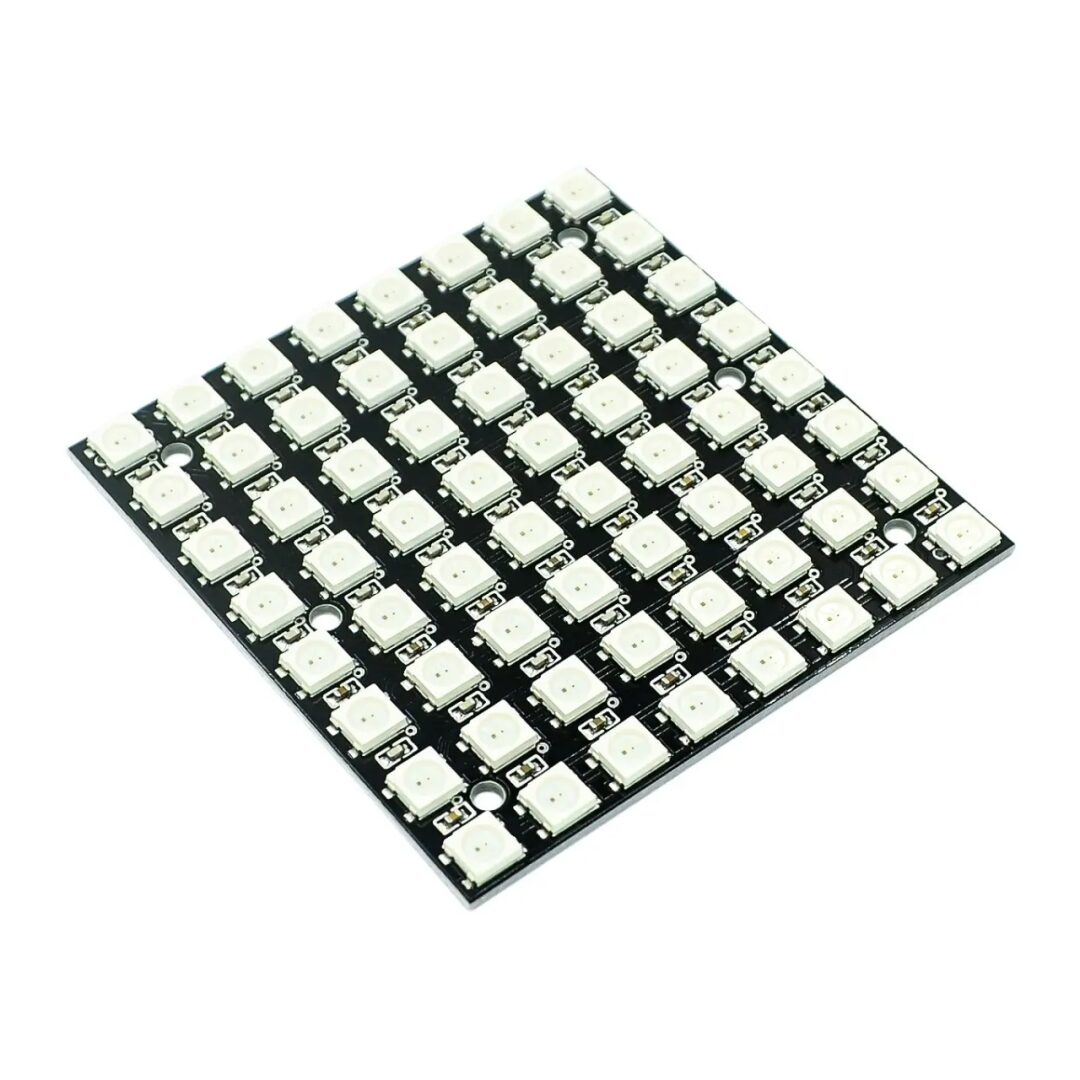
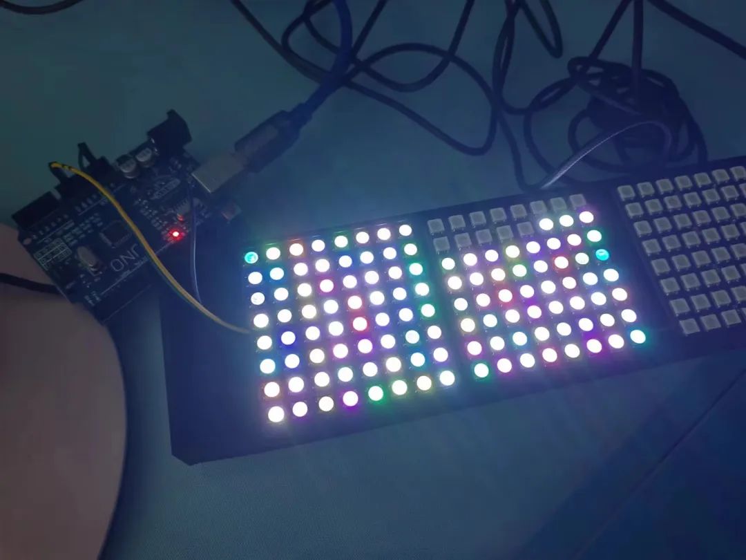
Hardware Selection: WS2812B Matrix Screen:
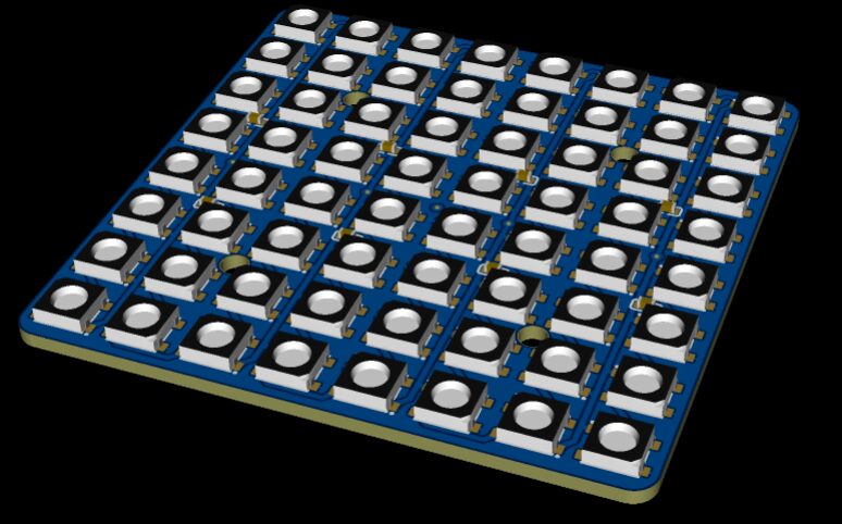
PCB Fabrication and 3D Export:
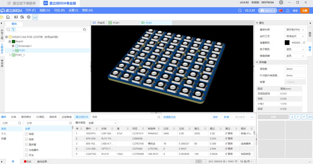
Using the JLCPCB platform for PCB design and exporting 3D models. These models will help us accurately design the enclosure in SolidWorks. JLCPCB is a professional PCB design service provider, offering online PCB design tools and manufacturing services. By using the JLCPCB platform, we can easily design a PCB that meets the size and connection requirements of the matrix screen and export a 3D model for later use.
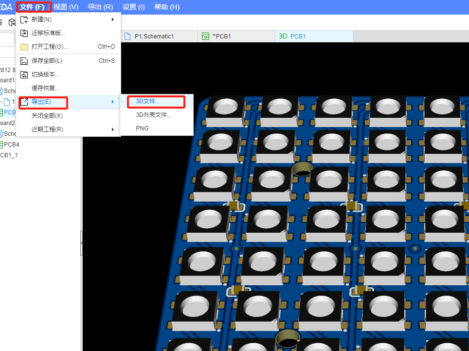
We can directly click in the EDA software: File -> Export -> 3D File.
SolidWorks:

SolidWorks is a powerful 3D CAD software suitable for mechanical design and manufacturing, allowing precise design of enclosures that meet the requirements for the matrix screen. By importing the 3D model of the PCB into SolidWorks, we can design a structurally sound and aesthetically pleasing enclosure model based on factors such as the dimensions of the matrix screen, connection interfaces, and mounting brackets. SolidWorks provides a rich set of design tools and functions to help us optimize the enclosure design, ensuring that the matrix screen and other components can be accurately installed and secured within the enclosure.
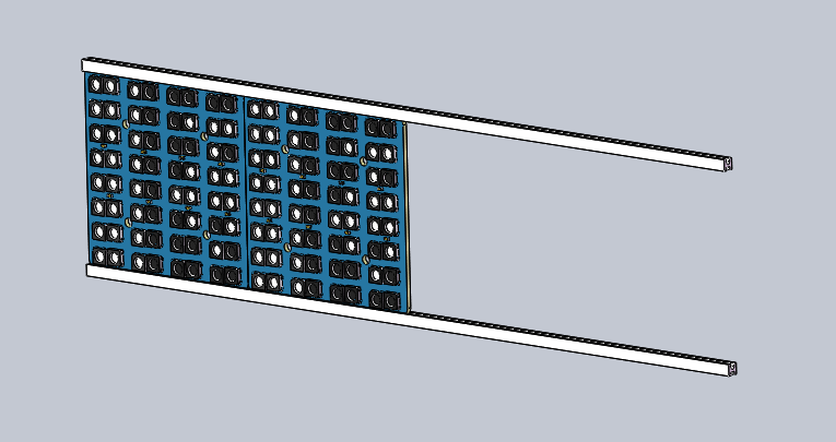
When designing the enclosure for the LED matrix screen, factors to consider include the size of the matrix screen, connection interfaces, mounting brackets, heat dissipation, and power supply. Through SolidWorks, we can accurately design an enclosure that meets these requirements and ensure that the matrix screen and other components can be accurately installed and secured within the enclosure. Here, I designed two mounting bars based on the size of the 3D model to facilitate the synchronized installation of multiple LED lights.
3D Printing:
Select a 3D printing service provider such as TuoZhu or others for printing. 3D printing can provide highly customized enclosures while ensuring structural integrity and lightweight.
We will not explain the related tutorials for 3D printing here; you can set it up according to your own 3D printer.
Part Three: Implementation Process
Hardware Connection
Parallel Connection of Matrix Screens:
Connect multiple WS2812B matrix screens in parallel according to design requirements. Ensure the power, signal, and ground connections of each matrix screen are correct to avoid circuit short circuits or poor connections.
Enclosure Design and Fabrication
Complete PCB design on the JLCPCB platform and export the 3D model for later use in SolidWorks. SolidWorks enclosure design:
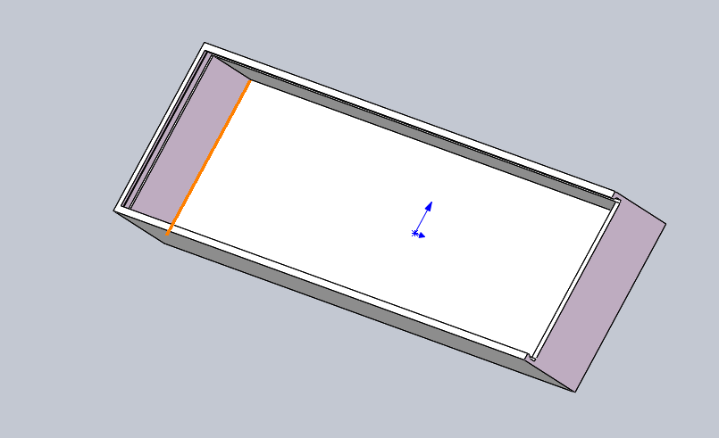
Using the exported PCB 3D model, design the matrix screen enclosure in SolidWorks. Considering factors such as the size of the matrix screen, connection interfaces, and mounting brackets, design a structurally sound and aesthetically pleasing enclosure model.
3D Printing
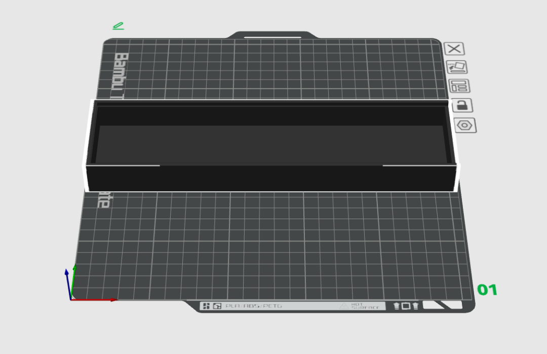
Import the enclosure model designed in SolidWorks into the 3D printer for printing. Select suitable materials and printing parameters to ensure the printed enclosure has sufficient strength and precision.
Assembly
Assembly: Assemble the printed components. Ensure the matrix screen is correctly installed inside the enclosure and connect the power and control wires. The assembly process is straightforward; simply insert the PCB from one side into the box, so we won’t include a picture here.
Because during the design, I intended for a closed structure, allowing the PCB to be inserted from one side of the control box. However, I did not anticipate that after soldering the wires onto the PCB, the rear end would require space for the wires to enter, which I did not reserve. Fortunately, the 3D printed part is plastic, so I used a pair of diagonal pliers to cut a notch.
On the other hand, during installation, I also found that the Arduino board did not have a reserved installation position and could only move around inside, which did not align with the original design intent. Therefore, next time I optimize, I need to consider the installation and placement of the control board.
Another point is that originally, when there was no enclosure design, the wiring was arbitrary, but once inserted into the control box, I found that the original wiring became complicated because the wires were inside the box, and during the insertion and pulling process, the wires were moving. How to achieve a simple installation of the wires is also one of the issues that need to be adjusted in the box’s functionality.
Part Four: Summary and Outlook
Summary
Through this project, we successfully created an enclosure integrated with the WS2812B matrix screen. The entire process covered multiple aspects, including hardware connections, PCB design, enclosure modeling, and 3D printing, enhancing our understanding of the design and manufacturing process of electronic products. The final matrix screen enclosure is not only aesthetically pleasing but also fully functional, capable of displaying a rich array of colors.
This design revealed many areas that need attention: during the SolidWorks design process, gaps need to be considered; otherwise, assembly may not be possible during 3D printing. Additionally, when designing in 3D, it is necessary to minimize supports to ensure the surface remains smooth during printing. Lastly, mark the functions of the PCB light board clearly for top, bottom, left, and right; otherwise, it will be troublesome to find out that the LED light board is reversed after assembly.
Outlook
In the future, we can consider further improving the enclosure design by adding ventilation holes to enhance heat dissipation or adding more interfaces to support additional functions. Furthermore, we can explore integration with smart home systems to achieve more interaction and display effects. These are all directions worth further research and implementation, providing broad possibilities for future projects.