When you open an ECU, and see the densely packed components inside, do you sometimes feel confused and unsure of where to start? This is completely normal.
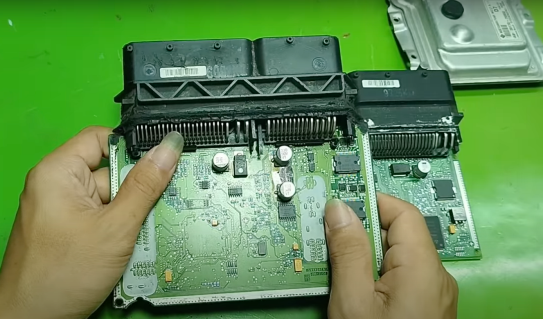
Today, we will help everyone understand how the components in the ECU work, while also assisting in the smoother repair of the ECU. The ECUs used for demonstration are taken from two different cars, from the Kia and Hyundai brands.
Autocar Star丨Source
Automotive Development Circle丨Produced by
MCU of the ECU Main Control
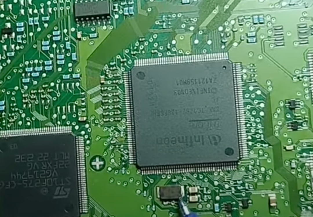
First, this is the main control center of the ECU, which uses the Infineon TC17xx series SAK-TC1762-128F66HLAC. It plays a core role, processing almost all data related to engine operation, as well as data from other vehicle control systems.
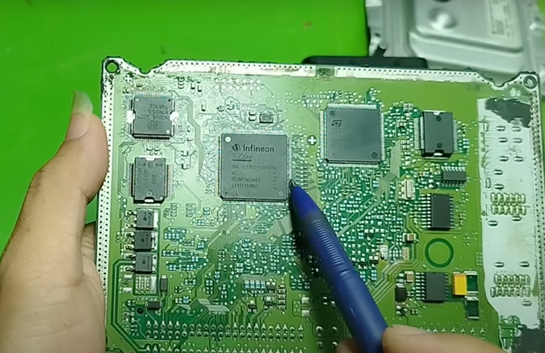
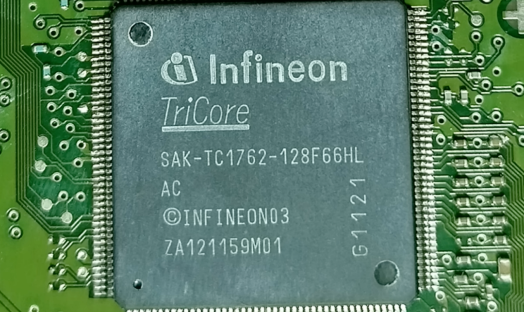
Specifically, it has five main functions:
First, it reads sensor signals. For example, it can read signals from the crankshaft position sensor, camshaft position sensor, manifold absolute pressure sensor (MAP), mass air flow sensor (MAF), temperature sensors, and oxygen sensors (O2).
Second, it processes data through control algorithms. For instance, it calculates how much fuel to inject based on the engine’s operating conditions or adjusts the ignition timing.
Third, it sends control signals. It sends signals to actuators, such as fuel injectors, ignition coils, exhaust gas recirculation valves (EGR), and electronic turbochargers, all of which are controlled by it.
Fourth, it manages communication over the Controller Area Network (CAN) or Local Interconnect Network (LIN). In simple terms, it communicates with other ECUs in the vehicle’s electrical system.
Fifth, it is responsible for fault monitoring. It can protect the system and perform diagnostic functions, such as those related to the On-Board Diagnostics (OBD) system. This is the important role of the internal microcontroller of the ECU.
Another MCU
Next, we look at the larger chip next to it, which is the ST10F275-CFG. This is also a central processing unit, or MCU, similar to the previously mentioned tri-core processor TC1762, but it has a relatively simpler structure.
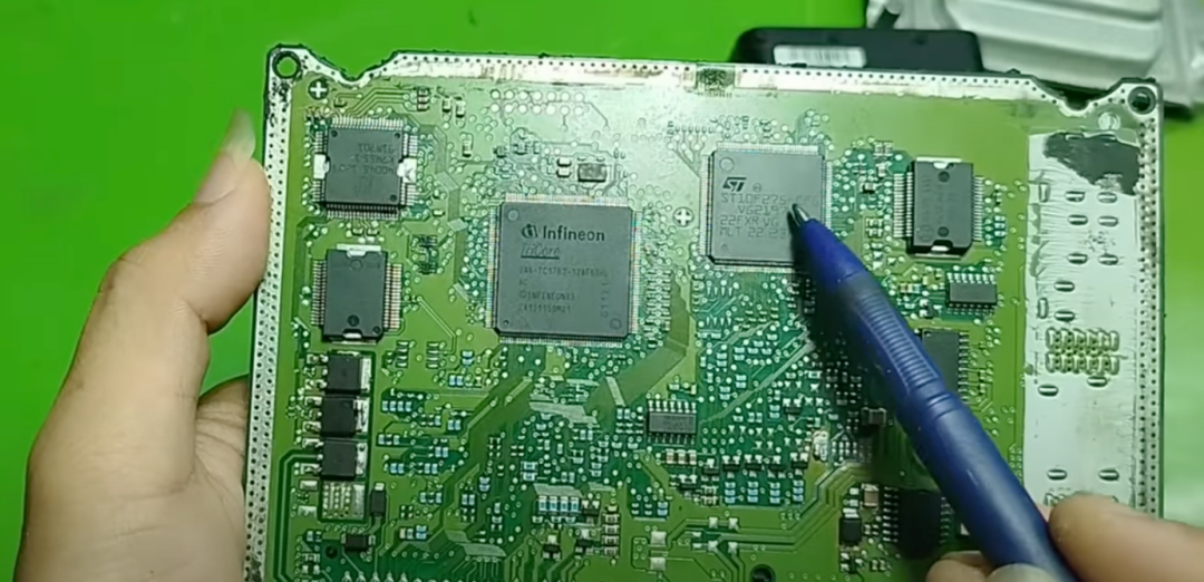
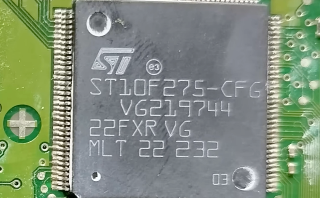
Its main functions include:
First, it collects signals from various sensors, such as the MAP sensor, MAF sensor, camshaft sensor, crankshaft sensor, temperature sensor, and oxygen sensor.
Second, it processes these signals and performs control calculations based on pre-written algorithms. These algorithms can be used to control the engine and even the transmission.
Third, it sends control signals to actuators, such as controlling fuel injectors, ignition coils, variable valve timing solenoid valves, and fuel pumps.
Fourth, it manages CAN communication, enabling information exchange with other ECUs in the vehicle.
Fifth, it performs diagnostic functions and stores diagnostic trouble codes (DTC). When a vehicle has issues, these codes help technicians quickly identify the problem.
Sixth, when the ECU is powered on, this integrated circuit loads the control program from flash memory, thus starting its operation.
In simple terms, this ECU uses two independent microcontrollers, one for controlling the engine and the other for controlling the transmission. This separated design allows the ECU to operate more reliably and efficiently handle the operations of both systems independently.
Smart Power Integrated Circuit
Next, we look at the integrated circuit model Bosch 30639 (also possibly V61036L0). This is a smart power integrated circuit, also known as a driver integrated circuit.
It plays a key role in controlling vehicle actuators, specifically, this integrated circuit is mainly used to control the following components: fuel injectors, EGR valves, intake control valves, relays, and even boost solenoid valves.
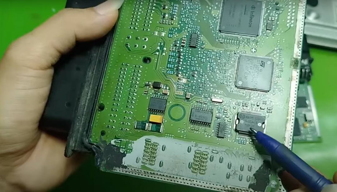
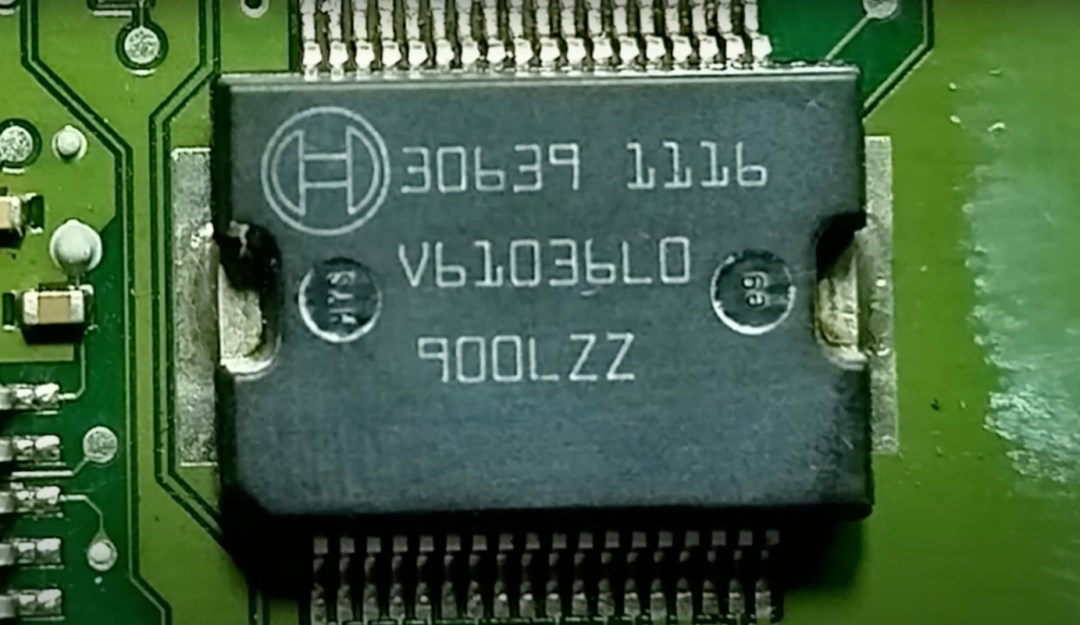
As a power integrated circuit, it can withstand large currents and adapt to harsh working environments in the engine compartment. Additionally, it has built-in protection features, such as overcurrent protection, overheat shutdown protection, and short-circuit protection. It can be said that it acts like a “silent warrior,” executing the commands issued by the central microcontroller, allowing actuators to operate accurately and safely.
Driver Integrated Circuit
Now, let’s look at another integrated circuit model 40048. This is a driver integrated circuit specifically designed to handle control signals. As I understand it, it serves as the “interface” between the main microcontroller (MCU) and the input/output signals within the ECU.
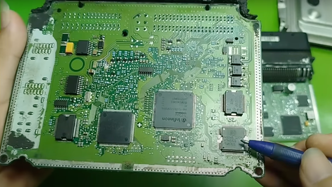
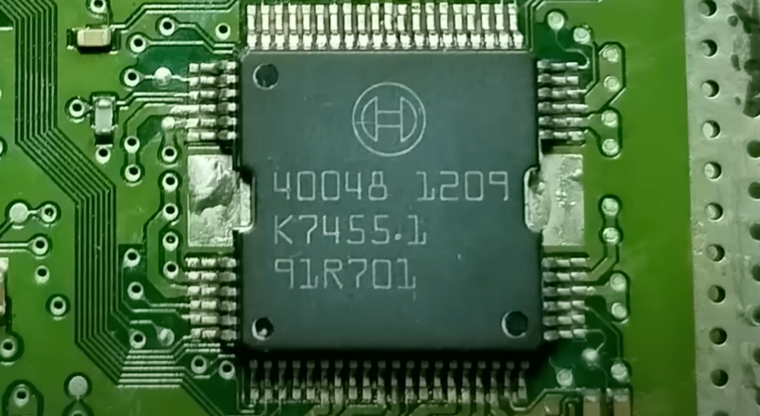
Specifically, at the output end, it receives control commands from the MCU and then controls actuators, such as fuel injectors, ignition coils, relays, and fuel pumps.
At the input end, it receives signals from sensors, such as the MAP sensor, throttle position sensor (TPS), coolant temperature sensor (ECT), and oxygen sensor (O2). These signals are mostly analog signals, and this integrated circuit converts them into digital data before sending them back to the MCU for processing.
In other words, this integrated circuit acts like a “communication bridge,” helping the MCU control external devices while accurately reading the input signals from sensors. It is small in size but plays a crucial role in ensuring the stable and precise operation of the ECU.
Low-Side Power Output Driver
Next to it, there is an Infineon TLE6232GP, which is a low-side power output driver, typically used to control smaller components in the system. Specifically, this integrated circuit generally controls the following components: fuel injectors, solenoid valves, fuel pump relays, cooling fan relays, and even indicator lights or other small load devices.
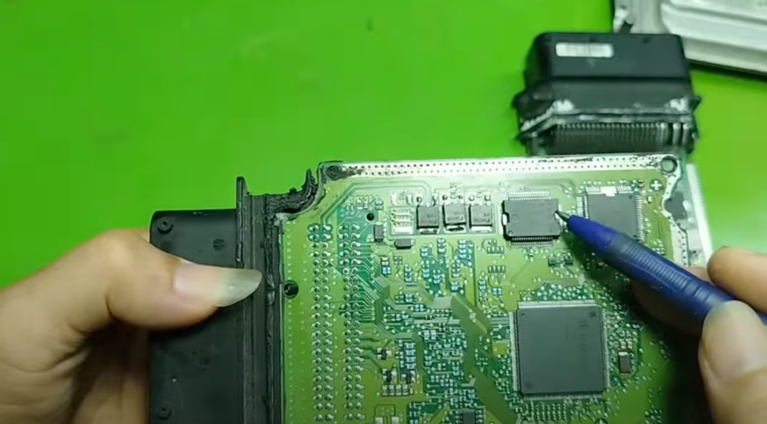
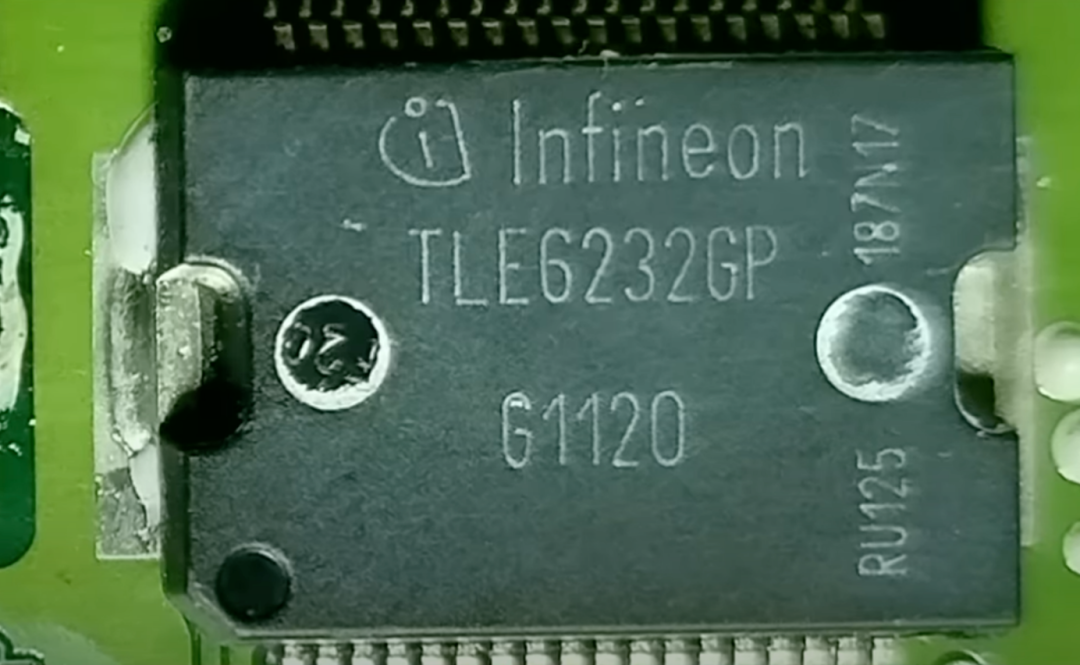
Although it is a low-power integrated circuit, its role is still important. With it, the MCU does not need to directly handle the output tasks of these small loads. Controlling them through this circuit improves system stability and provides better protection.
Follow and star the EEFocus account
Scan to reply with “Trial” to join the trial group for board cards and participate in free trials
Analysis of Other Small Chips
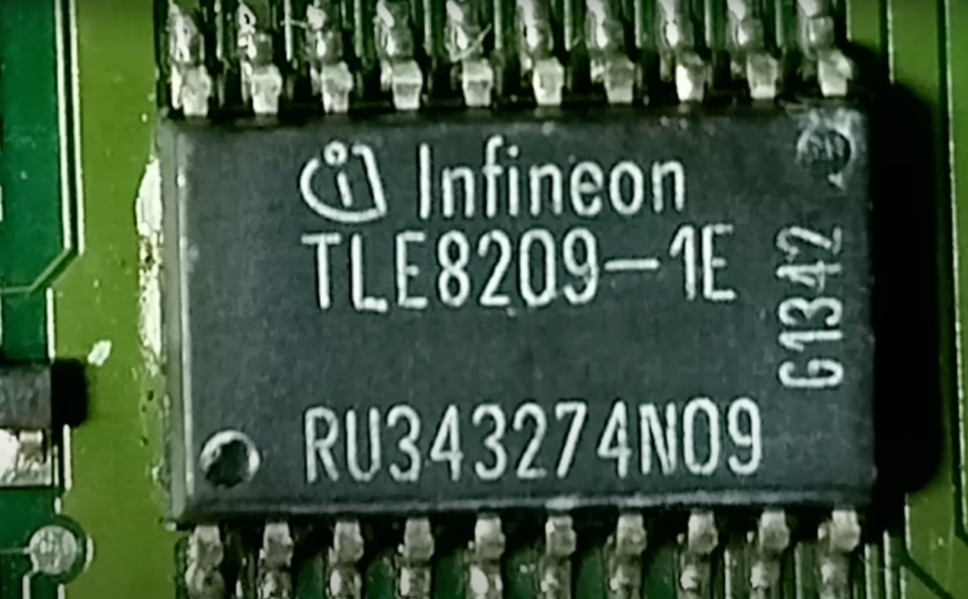
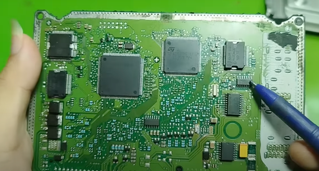
Infineon TLE8209-1E is a dual H-bridge driver designed specifically to control DC motors or inductive loads such as coils and solenoids.
This chip is typically used to control small motors in vehicles, such as wiper motors, electronic throttle control motors, electric seat and mirror adjustment motors, linear valves, and small electric pumps. It can also be used to drive solenoid coils, relays, or other inductive actuators. It is an essential component in scenarios where motion actuators need to be controlled while ensuring safe and precise operation.
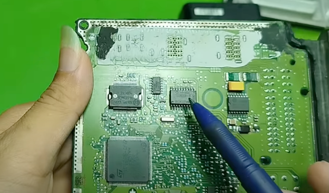
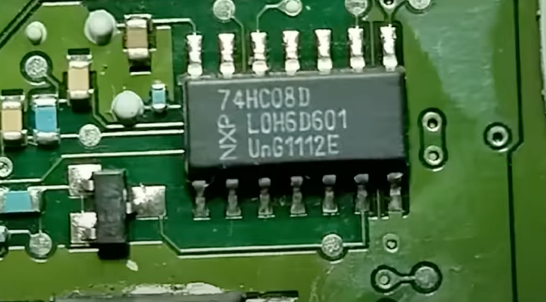
74HC14 is a logic inverter integrated circuit that contains six NOT gates, each of which is a Schmitt trigger inverter. This integrated circuit is specifically used to process weak or noisy signals.
In the ECU circuit, it is typically responsible for the following tasks: cleaning sensor signals, such as those from the speed sensor, vehicle speed sensor, temperature sensor, or MAP sensor; conditioning input signals before sending them to the MCU; and generating stable square wave pulses from weak or unstable signal sources.
In other words, this chip acts like an intelligent signal filter, converting unstable signals into cleaner digital signals that are easier to process. It is small in size but plays an extremely important role in ensuring that the signals delivered to the MCU are always clean and accurate.
Chip Analysis on the Back of the ECU
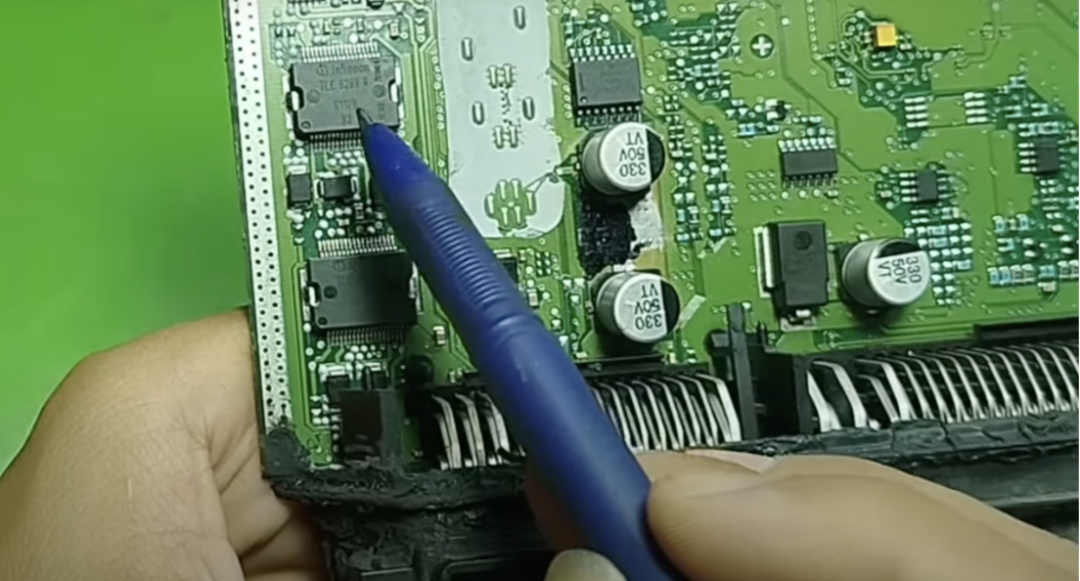
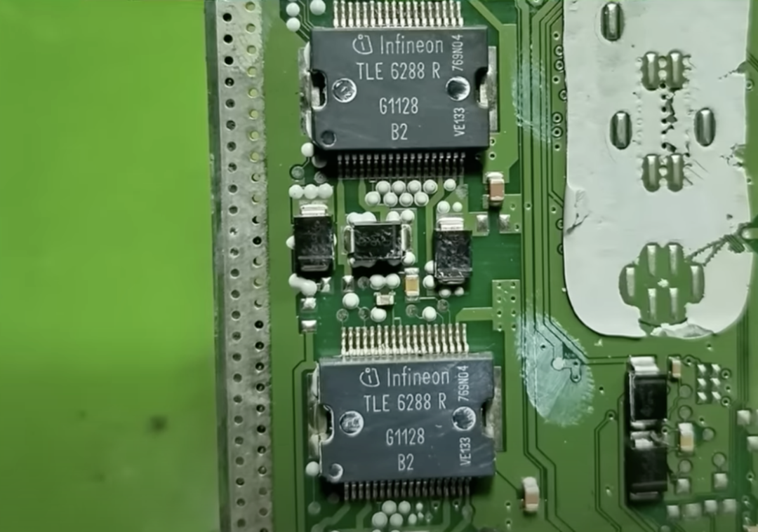
Next, turn over the ECU to see two identical Infineon TLE6288R chips. They are smart H-bridge driver integrated circuits designed specifically for controlling high-precision DC motors.
This type of chip is commonly used to drive actuators controlled by motors, which is very common in modern automotive systems, such as electronic throttle control (ETC) systems. This integrated circuit receives signals from the electronic throttle pedal and controls the motor to open or close the throttle based on driving demands. It also controls variable valve motors, such as those in variable valve timing (VVT) systems, EGR systems, or variable nozzle turbochargers (VNT). These valves are typically driven by rotary or linear motors, and the TLE6288R can control them with high precision.
Additionally, this chip can drive electronic water pumps, adjusting the pump speed based on engine temperature. With its smart design and high accuracy, the TLE6288R is a key component for ensuring stable and reliable operation of motor-driven actuators.
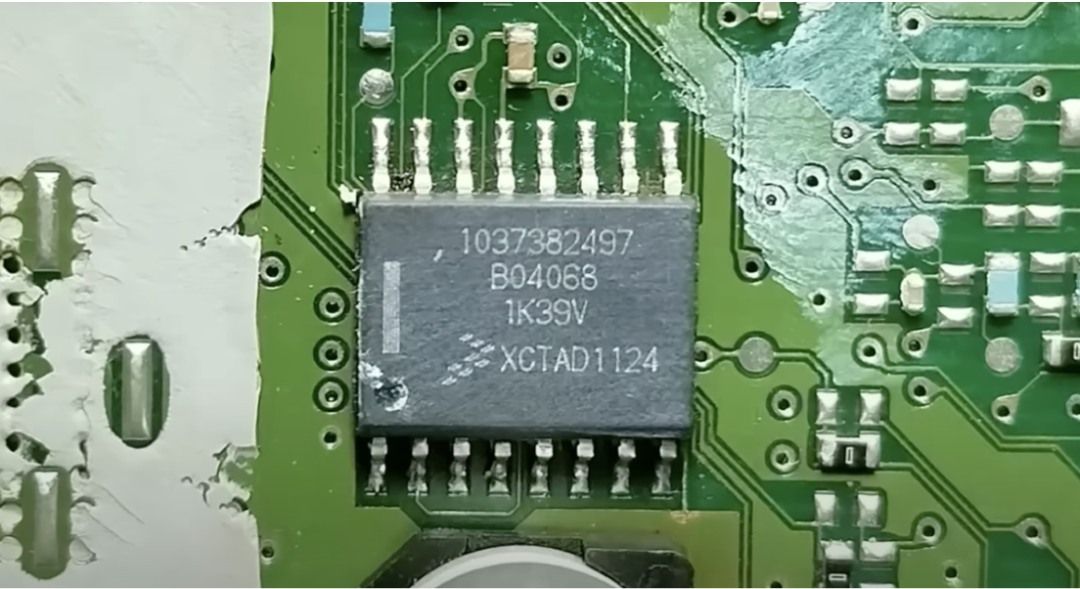
1037382497 (XCTAD1124) is a microcontroller or application-specific integrated circuit.
This chip is versatile, capable of processing both analog and digital signals. Its specific functions include: first, sensor signal processing. It has a built-in analog-to-digital converter (ADC) that converts the analog signals output by sensors into digital signals; second, output control signals, generating pulse-width modulation (PWM) signals or digital output signals to control external devices, such as valves, relays, or small motors; third, communication functions. This integrated circuit can communicate with other vehicle systems, supporting protocols including CAN, LIN, and K line (K-Line), enabling data exchange with other control modules in the vehicle; finally, security functions. In some systems, this integrated circuit may store anti-theft passwords or run authentication algorithms for the immobilizer system to prevent unauthorized engine starts.
Overall, this is a powerful microcontroller that integrates multiple functions such as signal processing, communication, and security into a compact Bosch application-specific integrated circuit, playing a crucial role.
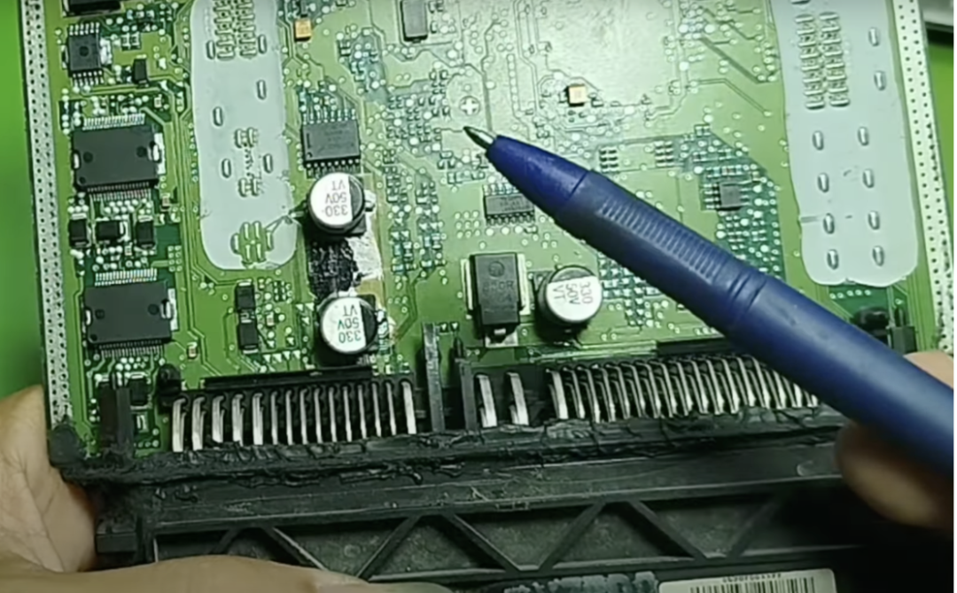
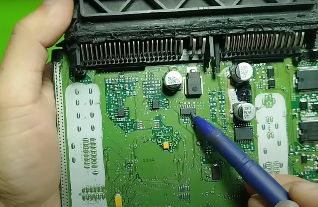
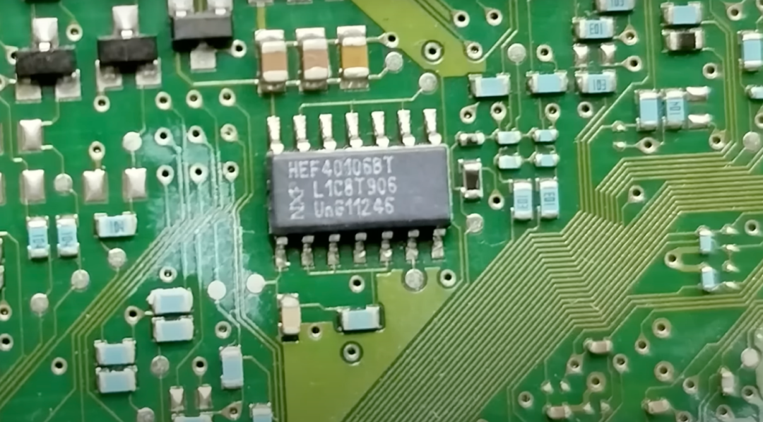
HEF4093BT is a six Schmitt trigger inverter. In simple terms, this integrated circuit contains six NOT gates, each of which is a logic inverter. Its uniqueness lies in the fact that each logic gate is equipped with a Schmitt trigger, which gives it excellent noise filtering capabilities, allowing it to clean weak, noisy, or unstable analog signals and convert them into clear, clean logic signals.
It functions similarly to another surface-mounted integrated circuit we analyzed earlier. This indicates that within the same ECU, manufacturers often use multiple integrated circuits of the same type to handle different signals.
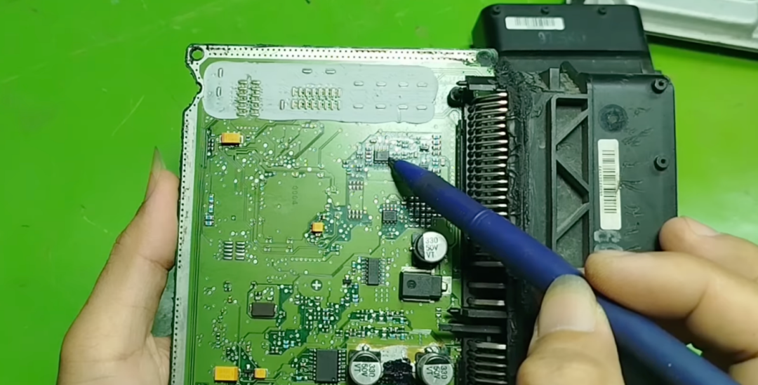
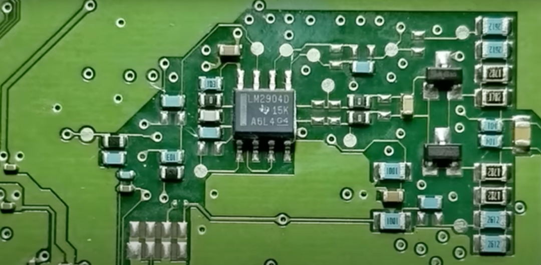
TI’s LM2904 is an operational amplifier (Op-Amp), whose main function is to amplify weak signals output by sensors, such as signals from oxygen sensors and manifold absolute pressure signals from the MAP sensor, which require amplification.
In addition, this integrated circuit can also be used for voltage threshold comparison, such as determining when to turn on or off a metal-oxide-semiconductor field-effect transistor (MOSFET) in control circuits. In simple terms, the LM2904 acts like a pair of “sharp eyes,” capable of amplifying weak signals and helping the ECU make precise control decisions.
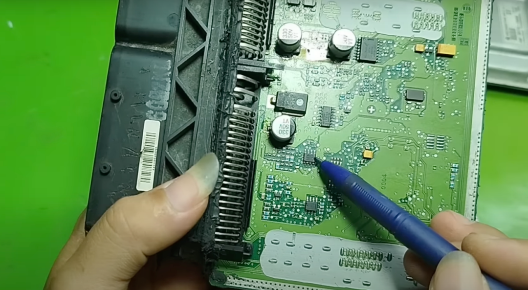
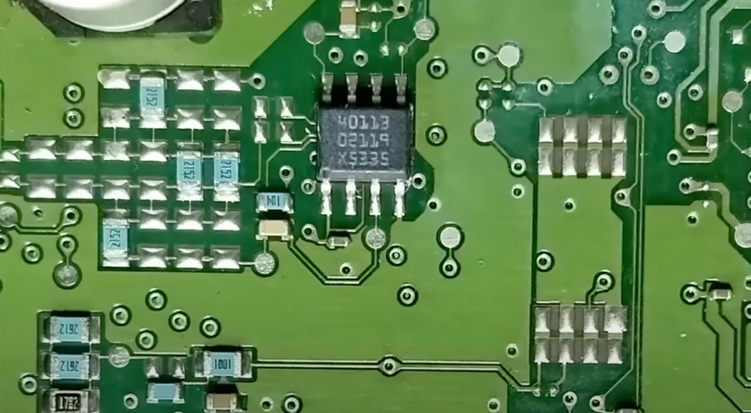
CD40113 may be a digital logic circuit, but it could also be a customized version based on the standard 40113 series. Regardless of which, we can understand its functions as follows: first, it stores logic states, meaning it can act like a memory bit, saving a binary value; second, it divides clock signals, which is very useful in counter circuits or pulse generation circuits.
This chip is commonly used in applications such as ignition trigger circuits, processing rotation sensor signals, and generating fuel injection control pulses. Additionally, it can be used to generate delay pulses or perform simple PWM control. Overall, this is a versatile digital logic integrated circuit that helps ensure smooth and accurate collaboration of various processes within the ECU.
Analysis of Auxiliary Components
At this point, we have introduced most of the key integrated circuits in this ECU. Now, let’s take a look at the auxiliary components in the ECU circuit, understand their roles, and why they are equally important.
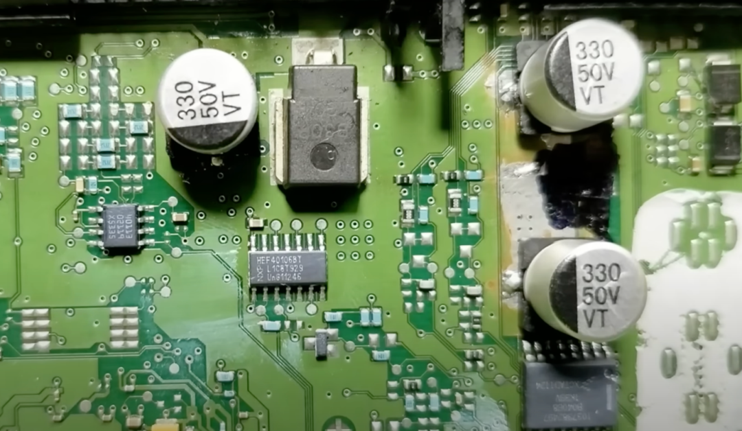
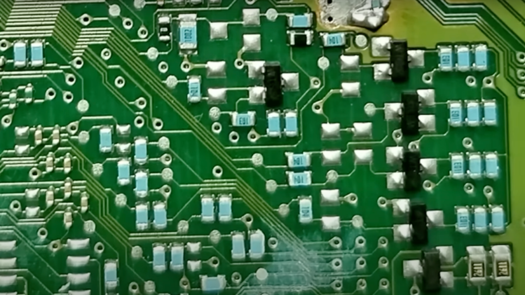
First, look at these small white components, one end marked; they are capacitors, specifically filtering capacitors for the power input of the ECU. The smaller yellow capacitors are also filtering capacitors but are mainly used in lower voltage scenarios, such as in circuits of 1.8 volts, 3.3 volts, or 5 volts.
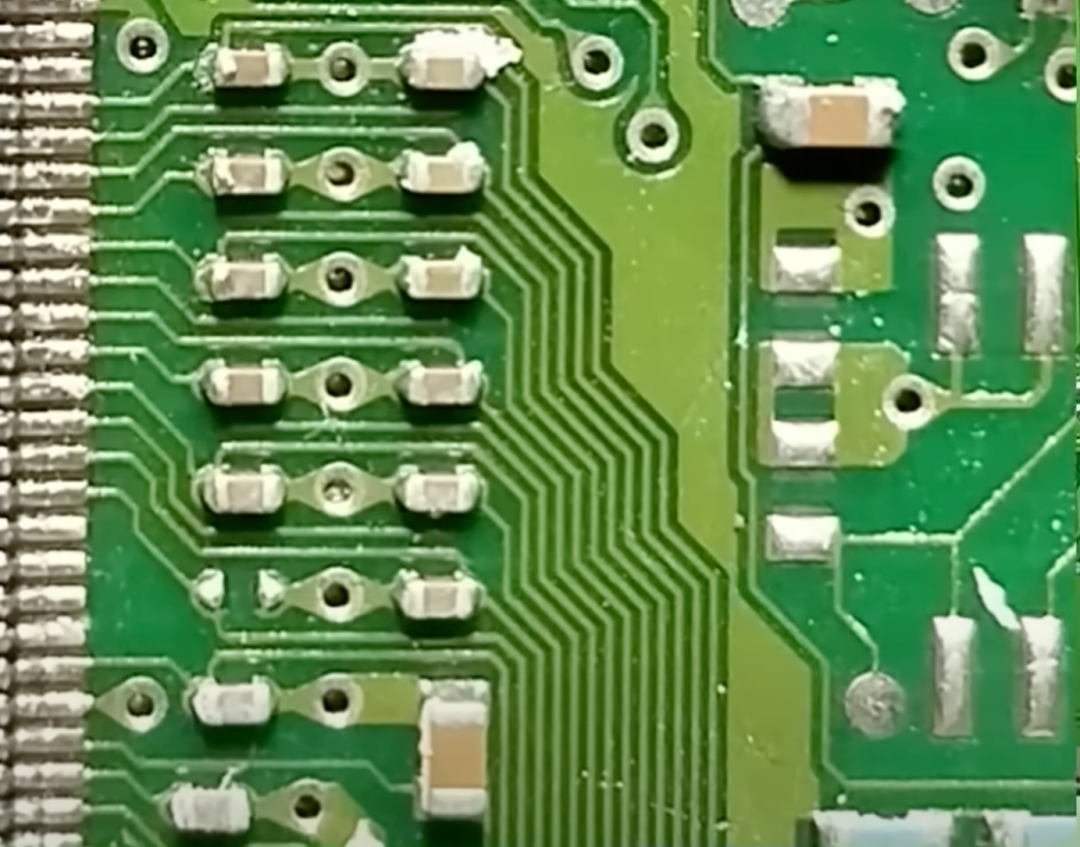
Additionally, you will see many small brown capacitors, all surface-mounted (SMD) capacitors. Capacitors serve many purposes in circuits, such as filtering noise, signal coupling, and stabilizing voltage.
Next, these black components, one end also marked, are diodes. Although small, diodes play a very important role in circuits, with main functions including: first, reverse polarity protection. If the battery or power supply is accidentally connected in reverse, the diode can block reverse current, protecting integrated circuits, drivers, and microcontrollers from damage; second, overvoltage and surge protection. When disconnecting inductive loads such as fuel pumps, fuel injectors, relays, or cooling fans, a high voltage spike, known as back EMF (flyback voltage), can occur. By placing a diode in parallel across the coil, this spike voltage can be absorbed, protecting components like transistors or integrated circuit drivers; third, AC signal rectification. Sensors like camshaft position sensors (CMP) and crankshaft position sensors (CKP) output AC pulse signals, and diodes can convert them into DC pulses or remove the negative half of the signal.
Additionally, if it is a Zener diode, it can also stabilize input voltage.
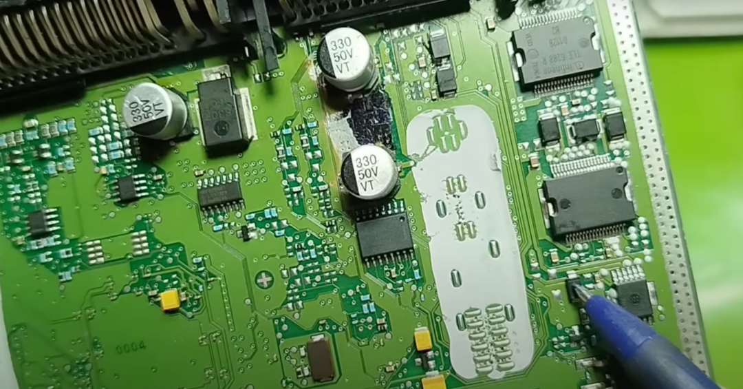
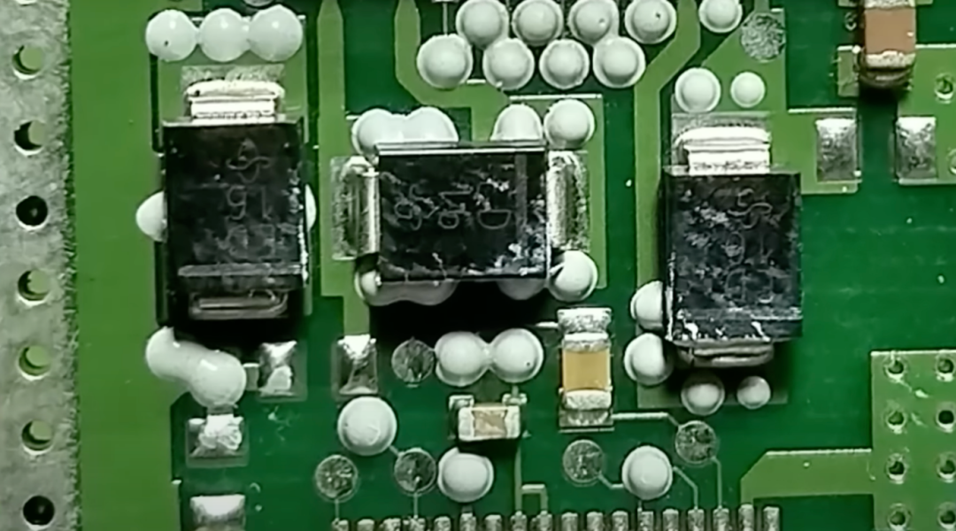
Now, look at these larger components with three pins; they are power MOSFETs (metal-oxide-semiconductor field-effect transistors) used to switch large loads, such as fuel pumps, fuel injectors, and control valves.
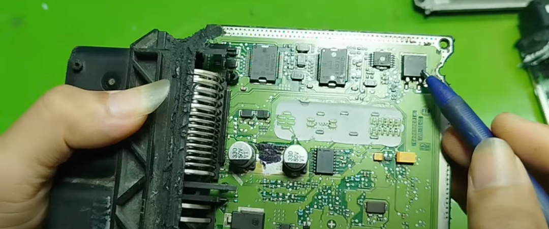
Those smaller three-pin components may be transistors or small MOSFETs used to switch small signals within the circuit.
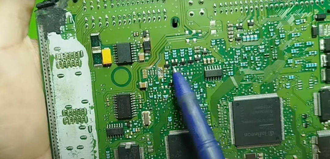
Do you see these small green or black components? They are surface-mounted (SMD) resistors. Some resistors will have their resistance values printed on them, while others will not, but they all belong to resistors and play important roles, such as voltage division, current limiting, or providing bias voltage.
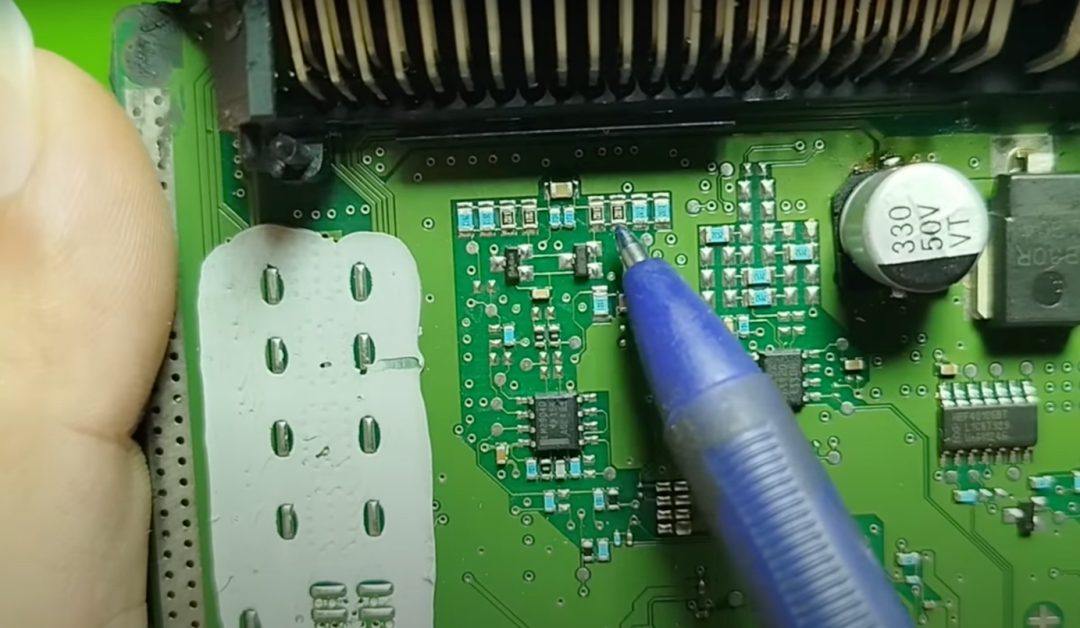
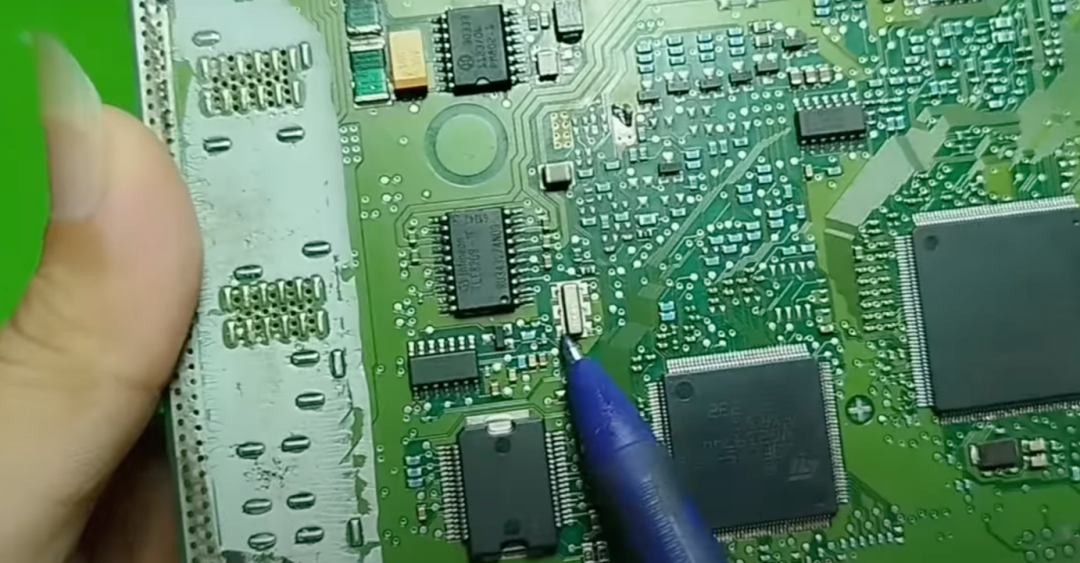
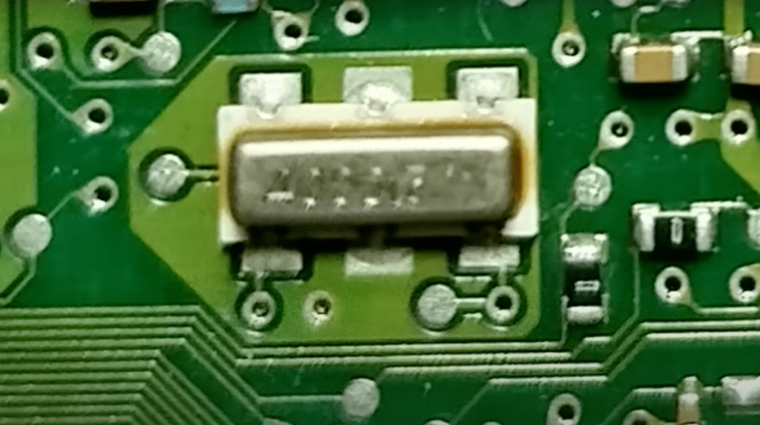
Now, look at these three small components; based on their shape and the codes printed on them, they are crystal oscillators (referred to as crystals). In simple terms, crystals act like the “heart” of the MCU, generating precise oscillation signals that allow the MCU to operate stably at a fixed frequency.
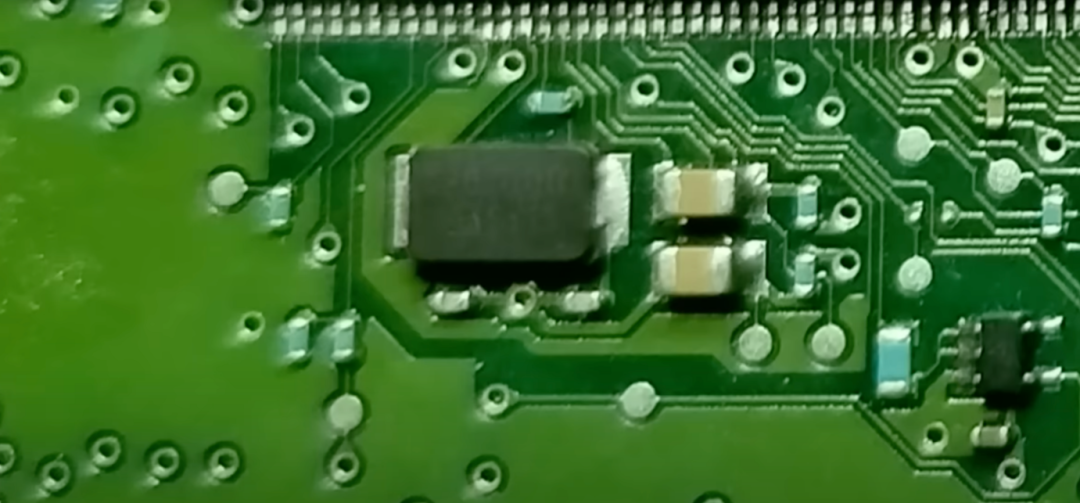
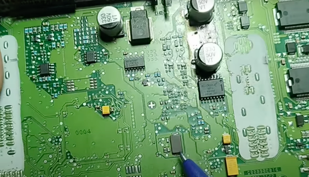
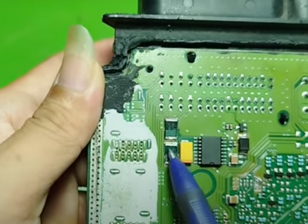
Finally, do not overlook these two special components; they are current sensing resistors. When current flows through them, a very small voltage is generated, which has three main uses: monitoring power consumption, controlling loads based on the required current, and protecting the circuit in case of overcurrent. They act like intelligent fuses, triggering protection mechanisms when the current is too high, preventing damage to the entire circuit.
Comparison of Another Key Component in the ECU
At this point, we have introduced all the key components inside the first ECU. Now, let’s look at another ECU, which comes from an engine equipped with a manual transmission (MT). We will compare this ECU with the ECU of an automatic transmission vehicle to see what differences exist.
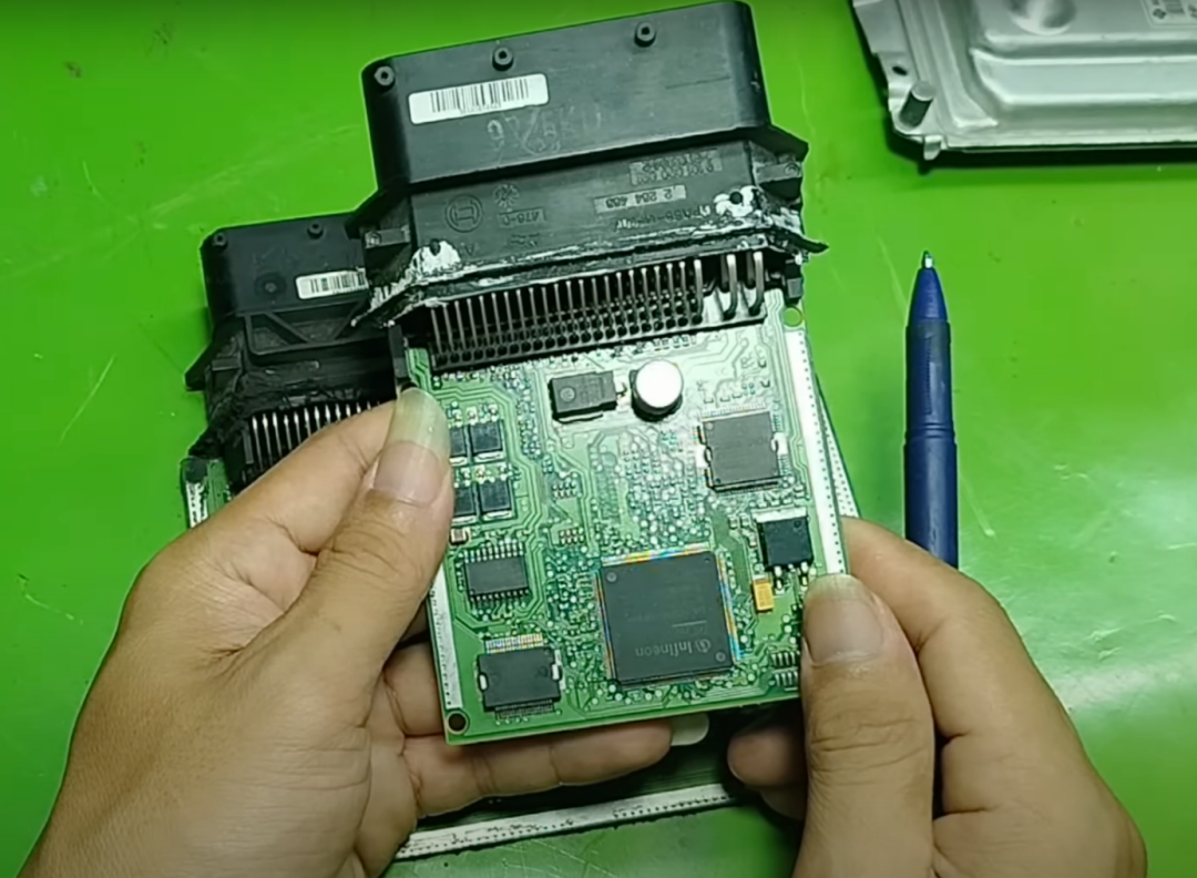
You will first notice that this ECU lacks the transmission control section, so it only has one main MCU— a single microcontroller responsible for controlling the entire engine system.
Upon closer inspection, you will find that this ECU still has all the components we are familiar with, just like the ECU of an automatic transmission vehicle: it has driver integrated circuits (also known as power integrated circuits), transistors, MOSFETs (for controlling signals or loads), as well as capacitors, resistors, protection diodes, and crystal oscillators that provide stable operating signals for the MCU.
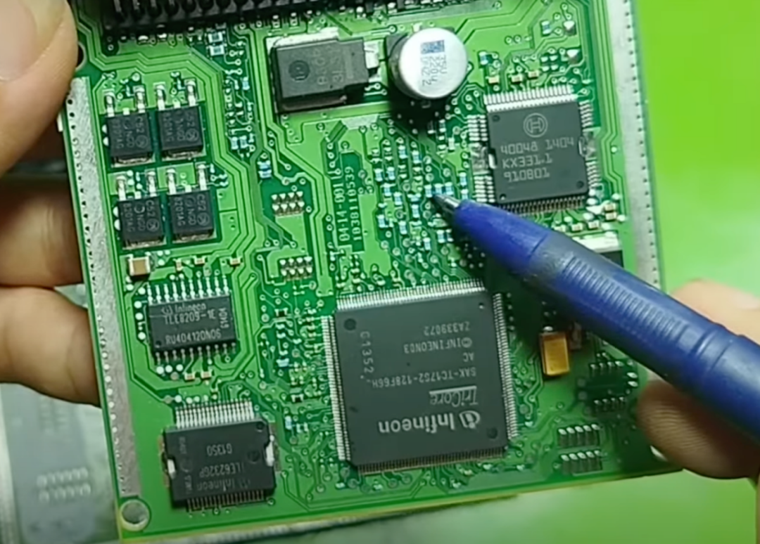
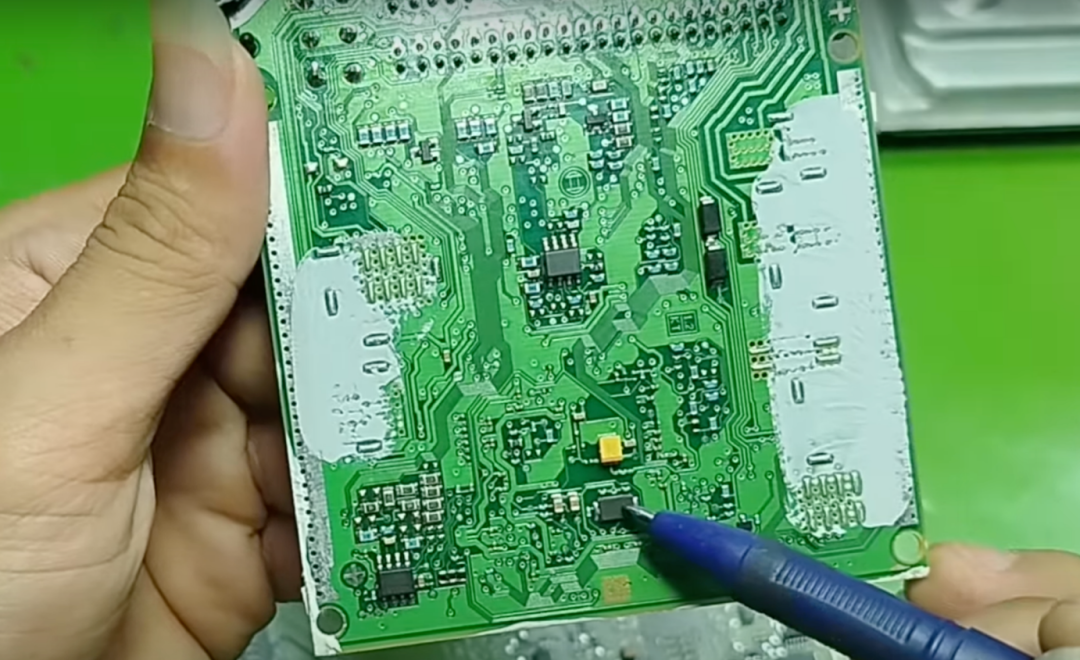
So overall, the circuit design of the manual transmission ECU is not much different from that of the automatic transmission ECU; the only difference is the removal of the transmission control section. This means its circuit diagram will be slightly simpler, and diagnostics and repairs may be easier.
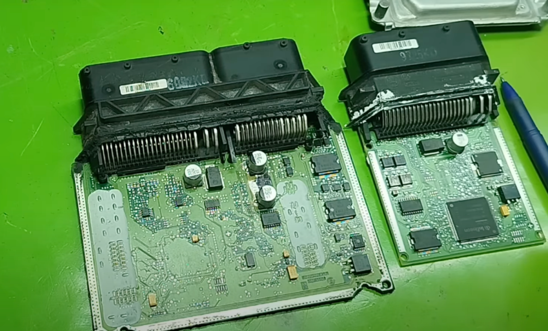
Next, I will open another electric power steering (EPS) ECU. Looking at its interior, it is actually not much different from the previous ECU: it still has crystal oscillators, MOSFETs, various integrated circuits, as well as capacitors and resistors.
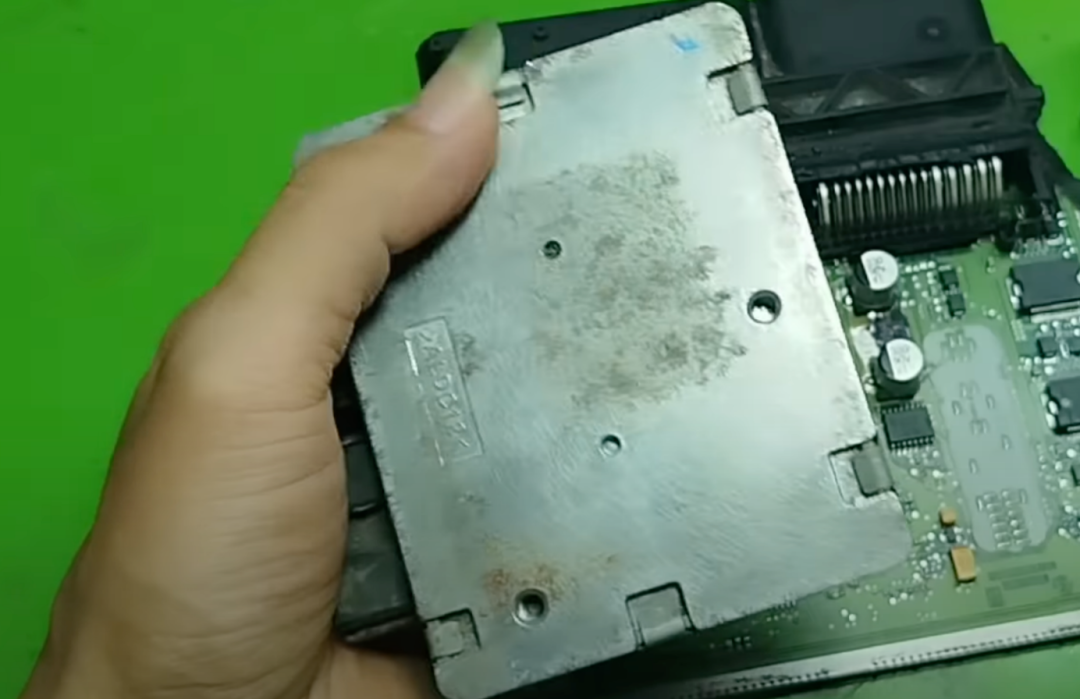
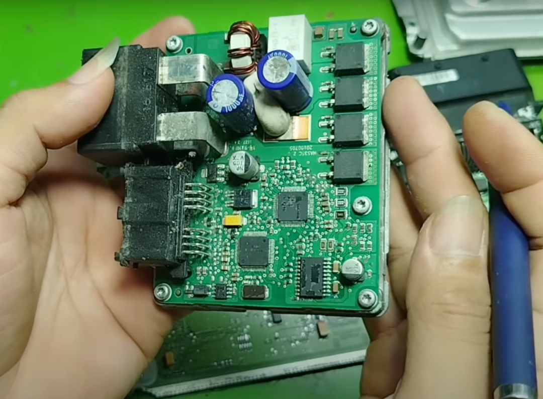
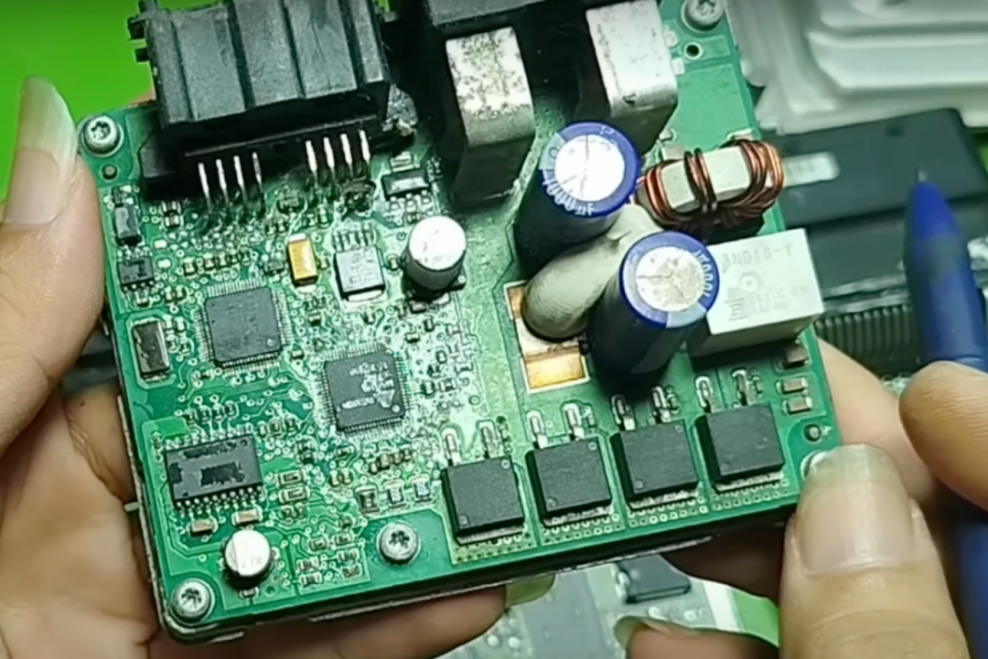
Therefore, essentially, whether it is an engine ECU, transmission ECU, or steering ECU, the types of basic components used are the same. The real difference lies in how each integrated circuit operates based on the different functions of the ECU; each integrated circuit is programmed and controlled to perform different tasks.
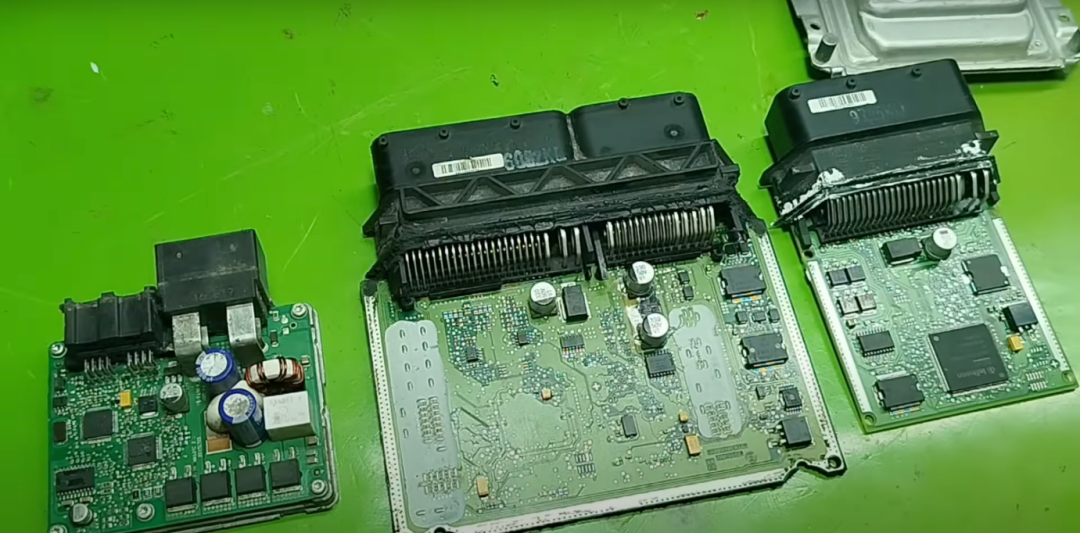
For example, a driver integrated circuit in the engine ECU may be used to control fuel injectors or EGR valves; but if the same integrated circuit is placed in the steering ECU, it may be used to control the steering motor. Therefore, understanding the working principles of each component is the most important.
END
Note: The cover image of this article is sourced from Freepik, self-made by the author, and publicly available media, all authorized.
Industry Community