Author | Wanli
Produced by | Automotive Electronics and Software
1. BOOT Source
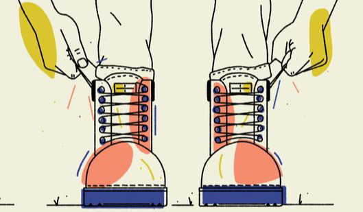
Boot as a startup term is indeed related to shoes. Since the startup of a computer begins with powering on the hardware, the software isn’t yet operational and needs a bootloader to initiate it. The action of pulling up the software requires the software itself to start and run, which is quite similar to the English proverb:
Pull oneself up by one’s bootstraps.
This means to lift oneself up by one’s shoelaces, symbolizing self-reliance and self-motivation. Due to the similarity in thought, in the early days of computer development, the bootloader was referred to as BootStrap Loader or Bootloader or simply Boot.
2. Introduction to Bootloader
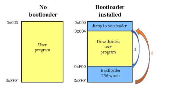 Figure 2: Diagram of Bootloader
3. Flash Bootloader
In fact, the Flash Bootloader can be considered the second program after the initial Bootloader is activated. The first activated Bootloader will assess the ECU status and then initiate the application program or enter the Flash Bootloader. Due to abbreviated expressions or vague concepts, it is common in practical scenarios to hear people confuse the Bootloader and the Flash Bootloader. We can maintain communication coherence based on the context, but we should clearly distinguish between the two in our minds.
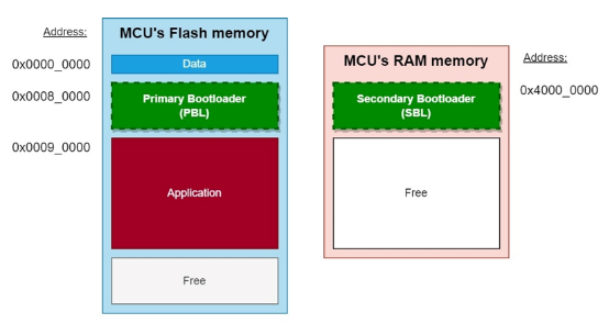
Figure 3: Diagram showing the relationship between Flash Bootloader and memory
The role of PBL is to guide the application software when it is valid. The PBL is stored in the Flash of the MCU chip and is generally programmed once at the factory. After powering on or rebooting the chip, the first code to execute is PBL. When software needs to be flashed, PBL can communicate with external diagnostic tools via Unified Diagnostic Services ( UDS), based on CAN or Ethernet and other lower-level bus protocols. After verifying the diagnostic tool’s permissions, PBL will download the SBL from the diagnostic tool to the MCU‘s memory RAM, which will then perform the flashing. The SBL includes all the services provided by the PBL as well as the Flash Driver and some additional UDS services. By triggering the UDS, the SBL will use the Flash Driver to erase old software and write new software to the corresponding storage area. The specific process is illustrated in the following diagram 4.
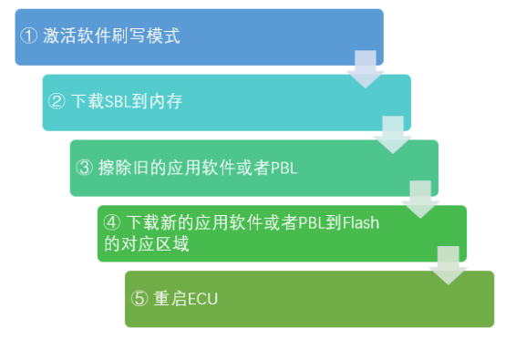
Figure 4: Diagram of the MCU flashing process
To prevent application software from being accidentally flashed or deleted, PBL generally does not include the Flash Driver and cannot directly manipulate the flash memory. Each time software is flashed, the SBL containing the Flash Driver must be reloaded into memory from the diagnostic tool. This division of labor between PBL and SBL has several advantages:
1. Prevent accidental flashing of application software.
3. The SBL can also flash update the PBL, increasing the overall flexibility of the Bootloader.
4. Startup and Flashing of SoC
The previously mentioned Flash Bootloader is aimed at traditional highly embedded systems. However, automotive colleagues may also notice that an increasing number of high-performance computing chips are being adopted in vehicles, with solutions like central automotive computers being increasingly common. These high-performance computing chips are often referred to as SoC (System on Chip). The startup and flashing solutions for SoC are similar to those for MCU, but due to the complexity of their internal storage management systems and internal buses, the specific implementation of startup differs slightly from that of MCU, resembling the details we are familiar with in personal computers. The overall startup process is illustrated in the following diagram.
Figure 5: Diagram of BIOS and UEFI startup process
Traditional computer startup generally uses the upper part of the diagram above, which is the BIOS startup. BIOS stands for Basic Input Output System, and it is the first point of contact between computer hardware and software. BIOS‘s code is typically embedded in the computer’s motherboard’s EEPROM. The BIOS can perform basic self-checks after the computer is powered on and instruct the computer on how to perform fundamental functions, such as booting and keyboard control. You can also configure startup parameters within the BIOS. Yes, that’s why when we reinstall the computer system, we can choose to boot from a CD or hard drive in the BIOS. Then, the BIOS will call the MBR (Master Boot Record) at the starting position of the hard drive, and then it will activate the Bootloader, followed by the operating system kernel, and then the operating system and applications.
Of course, the design of the BIOS has been around for a while. Most computers produced today use UEFI (Unified Extensible Firmware Interface), and the same goes for high-performance computing units in vehicles. Functionally, UEFI can be considered an upgraded version of BIOS.
UEFI is a micro-operating system that loads the Bootloader into memory and then executes additional operating programs. As a micro-operating system, UEFI runs on top of firmware and can support many more functions than BIOS, including security features like system verification. The most significant difference is that UEFI supports a larger addressing space and can operate in either 32 or 64 bit mode (while BIOS only supports 16 bit), meaning that UEFI can support larger hard drives or network shares and boot faster.
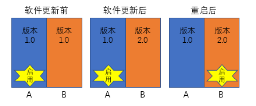
Figure 6: Diagram of A/B partition upgrade
5. Challenges in Automotive Controller Startup
At the beginning of the new year, everything is renewed. The beginning phase of each year has a significant impact on the entire year. The same is true for the startup of automotive controllers; a good start is half the battle. Due to the importance of startup, there are also many challenges that need to be addressed during the startup process. Among them, the most prominent challenges are related to information security and startup time.
Information Security Challenges During Startup
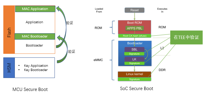
Figure 7: Diagram of a secure boot solution for an MCU and SoC
Challenges of Startup Duration
In-vehicle applications are very sensitive to startup time. For example, when reversing, we usually expect the rearview image to appear on the central control screen as soon as we start the car, buckle our seatbelt, and shift into reverse. Imagine if the entire startup duration took 1 minute; we would have to wait in the car for several dozen seconds or drive out without assistance, leading to a poor user experience.
To address this challenge, in-vehicle domain controllers or computing platforms frequently introduce sleep modes. This is similar to the sleep mode on our computers, where the contents of memory that would otherwise be lost during power-off are stored on the hard drive. The next time the system starts, all content is reloaded into memory rather than going through the entire process of reloading the Bootloader into the kernel and initializing everything. This allows the controller to maintain low power consumption for extended periods while being able to quickly start working when needed. Of course, this requires extra space on the hard drive to store the memory data during sleep. The diagram below illustrates the difference in startup times between traditional cold booting and waking from sleep mode.
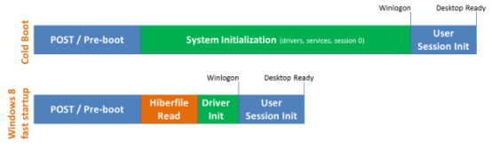
Figure 8: Comparison of cold boot and wake from sleep startup times for Windows 8
In addition to sleep mode, controllers can also shorten startup times by optimizing the secure boot strategy. In some cases, it may be permissible for the controller to first activate the Bootloader, operating system, and applications while recording their startup signatures, fingerprints, and other critical data. After the system is running, the TEE will verify the legitimacy of the already started system in the background; if it is found to be illegal, it will enter the appropriate safe mode. This approach sacrifices some security for shorter startup times, but it can be beneficial in reducing startup duration. Based on an analysis of the vehicle’s network security architecture, some relatively secure controllers (such as local controllers that do not communicate directly with external networks) can adopt this strategy.
Of course, product development is multidimensional rather than unidimensional. The startup process of automotive controllers should also be developed and balanced according to multidimensional standards. Just like how traditional non-smartphones had fast startup times and were safe without many viruses, they have now been replaced by smartphones that take longer to start and have greater security risks. The same goes for smart TVs that everyone watches at home during the Spring Festival. Under the trend of automotive intelligence, the startup process will continue to balance and become smarter, more efficient, and safer.
Welcome to all angel round and A round enterprises in the entire automotive industry chain (including the power battery industry chain) to join our group (We will recommend to 800 top automotive investment institutions)); we have communication groups for technology innovation company leaders, whole vehicle automotive industry, automotive semiconductors, key components, new energy vehicles, smart connected vehicles, aftermarket, automotive investment, autonomous driving, vehicle networking, and many other groups. Please scan the administrator’s WeChat to join the group (Please indicate your company name)