2016-11-24
Developing mobile handheld devices with touch screen human-machine interfaces is a complex design challenge, especially for projected capacitive touch screen designs, which represent the mainstream technology for current multi-touch interfaces. Projected capacitive touch screens can accurately locate the position of a finger touching the screen by measuring the minute changes in capacitance to determine the finger’s location. A key design consideration in such touch screen applications is the impact of electromagnetic interference (EMI) on system performance. Performance degradation caused by interference can adversely affect touch screen designs, and this article will explore and analyze these sources of interference.
Structure of Projected Capacitive Touch Screen
A typical projected capacitive sensor is installed beneath a glass or plastic cover. Figure 1 shows a simplified side view of a dual-layer sensor. The transmitting (Tx) and receiving (Rx) electrodes are connected to transparent indium tin oxide (ITO), forming a cross matrix, with each Tx-Rx junction having a characteristic capacitance. The Tx ITO is located beneath the Rx ITO, separated by a layer of polymer film or optical adhesive (OCA). As shown, the direction of the Tx electrodes runs from left to right, while the Rx electrodes run from outside to inside the paper.
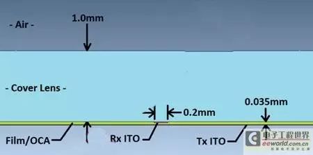
Figure 1: Reference for sensor structure.
Working Principle of the Sensor
Let’s analyze the operation of the touch screen without considering interference factors: the operator’s fingertip is assumed to be at ground potential. The Rx is maintained at ground potential through the touch screen controller circuit, while the Tx voltage is variable. The changing Tx voltage causes current to flow through the Tx-Rx capacitance. A carefully balanced Rx integrated circuit isolates and measures the charge entering Rx, with the measured charge representing the “mutual capacitance” connecting Tx and Rx.
Sensor State: Not Touched
Figure 2 shows a schematic diagram of magnetic field lines in the not-touched state. In the absence of a finger touching the screen, the Tx-Rx magnetic field lines occupy a significant space within the cover. The edge magnetic field lines project outside the electrode structure, hence the term “projected capacitive”.
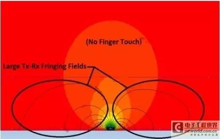
Figure 2: Magnetic field lines in the not-touched state.
Sensor State: Touched
When a finger touches the cover, magnetic field lines form between the Tx and the finger, replacing a significant portion of the Tx-Rx edge magnetic field, as shown in Figure 3. In this way, the finger touch reduces the Tx-Rx mutual capacitance. The charge measurement circuit detects the change in capacitance (△C), thus identifying the finger above the Tx-Rx junction. By measuring △C at all intersections of the Tx-Rx matrix, a touch distribution map for the entire panel can be obtained.
Figure 3 also shows another important effect: capacitive coupling between the finger and the Rx electrode. Through this path, electrical interference may couple to the Rx. Some degree of finger-Rx coupling is unavoidable.
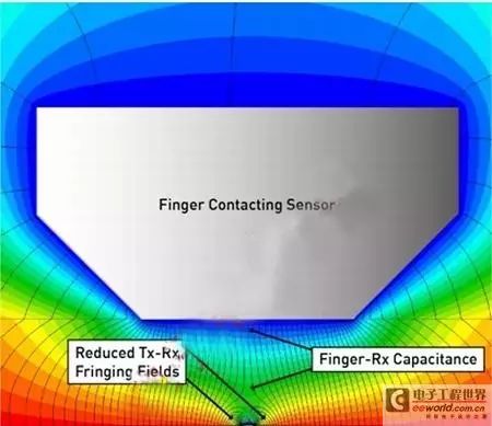
Figure 3: Magnetic field lines in the touched state.
Terminology
Interference in projected capacitive touch screens is generated through imperceptible parasitic paths. The term “ground” is commonly used to refer both to the reference node in a DC circuit and to a low-impedance connection to the earth: these are not the same term. In fact, for portable touch screen devices, this distinction is the fundamental reason for touch coupling interference. To clarify and avoid confusion, we use the following terminology to evaluate touch screen interference.
Earth: Connected to the earth, for example, through the ground wire of a three-pin AC power socket.
Distributed Earth: Capacitive connection of an object to the earth.
DC Ground: DC reference node of portable devices.
DC Power: Battery voltage of portable devices. Or the output voltage of a charger connected to portable devices, such as 5V Vbus in a USB charger.
DC VCC: Stable voltage powering electronic components of portable devices (including LCD and touch screen controllers).
Neutral: AC power circuit (nominally at ground potential).
Hot: AC power voltage, applying energy relative to the neutral.
LCD Vcom Coupled to Touch Screen Receiving Line
Portable device touch screens can be directly mounted on LCD displays. In a typical LCD architecture, the liquid crystal material is biased by transparent upper and lower electrodes. The multiple electrodes below determine multiple individual pixels of the display; the upper common electrode is a continuous plane covering the entire visible front of the display, biased at voltage Vcom. In typical low-voltage portable devices (e.g., mobile phones), the AC Vcom voltage oscillates between DC ground and 3.3V. The AC Vcom level typically switches once per display row, so the resulting AC Vcom frequency is half the product of the display frame refresh rate and the number of rows. A typical portable device’s AC Vcom frequency may be 15kHz. Figure 4 illustrates the coupling of the LCD Vcom voltage to the touch screen.
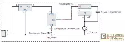
Figure 4: LCD Vcom interference coupling model. The dual-layer touch screen consists of separate ITO layers filled with Tx and Rx arrays, separated by a dielectric layer. The Tx lines occupy the entire width of the Tx array spacing, with minimum spacing required for manufacturing between lines. This architecture is referred to as self-shielding because the Tx array shields the Rx array from LCD Vcom. However, coupling may still occur through gaps between Tx lines.
To reduce architectural costs and achieve better transparency, single-layer touch screens mount Tx and Rx arrays on a single ITO layer, sequentially bridging each array through separate bridges. Thus, the Tx array cannot form a shielding layer between the LCD Vcom plane and the sensor Rx electrodes. This can lead to severe Vcom interference coupling situations.
Charger Interference
Another potential source of touch screen interference is the switching power supply of the power-supplying mobile charger. Interference is coupled to the touch screen through the finger, as shown in Figure 5. Small mobile chargers typically have AC power hot and neutral inputs but lack a ground connection. The charger is safety-isolated, so there is no DC connection between the power input and the charger’s secondary coil. However, this can still generate capacitive coupling through the switching power supply isolation transformer. Charger interference forms a return path through the finger touching the screen.
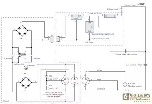
Figure 5: Charger interference coupling model.
Note: In this case, charger interference refers to the applied voltage of the device relative to the earth. This interference may be described as “common-mode” interference as it is equivalent on the DC power and DC ground. Power switch noise generated between the DC power and DC ground of the charger output, if not sufficiently filtered, may affect the normal operation of the touch screen. This power supply rejection ratio (PSRR) issue is another topic that will not be discussed in this article.
Charger Coupling Impedance
Charger switching interference is coupled through the leakage capacitance of the transformer primary-secondary windings (approximately 20pF). This weak capacitive coupling can be compensated by parasitic parallel capacitance that appears distributed between the charger cable and the powered device itself. When picking up the device, the parallel capacitance increases, which is usually sufficient to eliminate charger switching interference, preventing interference from affecting touch operations. When the portable device is connected to the charger and placed on a table, with the operator’s finger only contacting the touch screen, a worst-case interference scenario caused by the charger will occur.
Charger Switching Interference Components
Typical mobile chargers employ a flyback circuit topology. The interference waveforms generated by such chargers are relatively complex and vary significantly between chargers; they depend on circuit details and output voltage control strategies. The variation in interference amplitude is also significant, depending on the design efforts and unit costs invested by the manufacturer in the shielding of the switching transformer. Typical parameters include:
Waveform: Includes complex pulse-width modulation square waves and LC ringing waveforms. Frequency: 40~150kHz under rated load, dropping below 2kHz under very light load with pulse frequency or skip cycle operation. Voltage: Up to half of the power supply peak voltage = Vrms/√2.
Charger Power Supply Interference Components
At the front end of the charger, the AC power voltage is rectified to generate the charger high voltage rail. Thus, the switching voltage component of the charger is superimposed on a sine wave of half the power supply voltage. Similar to switching interference, this power supply voltage is also formed through coupling from the switching isolation transformer. At 50Hz or 60Hz, the frequency of this component is far lower than the switching frequency, so its effective coupling impedance is correspondingly higher. The severity of power supply voltage interference depends on the characteristics of the parallel impedance to ground, as well as the touch screen controller’s sensitivity to low frequencies.
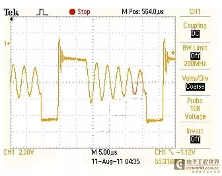
Figure 6: Examples of charger waveforms.
Special case of power supply interference: three-pin plugs without grounding, rated higher-power power adapters (e.g., laptop AC adapters) may be configured with three-pin AC power plugs. To suppress output EMI, chargers may internally connect the ground pin of the main power to the output DC ground. Such chargers typically connect Y capacitors between hot and neutral lines and ground to suppress conducted EMI from the power line. Assuming intentional ground connection exists, such adapters will not cause interference to powered PCs and USB-connected portable touch screen devices. The dashed box in Figure 5 illustrates this configuration.
For PCs and portable touch screen devices connected via USB, if a PC charger with a three-pin power input is plugged into a power outlet without a ground connection, a special case of charger interference will occur. The Y capacitor will couple the AC power to the DC ground output. A relatively large Y capacitor value can effectively couple the power voltage, allowing larger power frequency voltage to couple through the finger on the touch screen at relatively low impedance.
Today, projected capacitive touch screens widely used in portable devices are easily affected by electromagnetic interference, with interference voltages from internal or external sources capacitively coupled to the touch screen device. These interference voltages can cause charge movement within the touch screen, potentially confusing the measurement of charge movement when a finger touches the screen. Therefore, the effective design and optimization of touch screen systems depend on awareness of interference coupling paths, as well as efforts to mitigate or compensate for them as much as possible.
Interference coupling paths involve parasitic effects, such as transformer winding capacitance and finger-device capacitance. Properly modeling these effects can fully understand the sources and magnitudes of interference.
For many portable devices, battery chargers constitute the main source of interference for the touch screen. When the operator’s finger contacts the touch screen, the capacitance generated closes the charger interference coupling circuit. The quality of the internal shielding design of the charger and whether proper grounding design exists are key factors affecting charger interference coupling.
Does it feel complicated? Don’t worry, there are ways to address this situation! Important things said three times: Use our absorbing materials to stick between the source of interference and the interfered element, use our absorbing materials to stick between the source of interference and the interfered element, use our absorbing materials to stick between the source of interference and the interfered element!
Source: Electronic Engineering World, Edited by EMC Home
Join the EMC Rectification group chat, please add WeChat: 18126149816, and please indicate “EMC Rectification+ Company Name“!
If you like it, please follow us!Welcome and thank you for sharing and forwarding in your circle of friends!
Our Purpose
To be the most serious public account
Welcome to follow
Long press the QR code below to recognize and follow for free

Disclaimer: Some materials are sourced from the internet, and the purpose of reprinting is to convey more information and share, which does not mean agreeing with their views or verifying their authenticity, nor does it constitute other advice, only providing a communication platform, not responsible for their copyright. If there is any infringement, please contact us for timely modification or deletion. Email:[email protected]
Read the original text

Scan the WeChat QR code to follow this public account
—————————————————————————–
Disclaimer: The above content is reproduced from EMC Home, and the purpose of reprinting is to convey more information and share, which does not mean agreeing with their views or verifying their authenticity, nor does it constitute other advice, only providing a communication platform, not responsible for their copyright. If there is any infringement, please contact us for timely modification or deletion. Email:[email protected]
Follow Electromagnetic Compatibility (EMC) WeChat public account, to receive electromagnetic compatibility related content, long press the QR code below to recognize and follow:

Join Electromagnetic Compatibility (EMC) WeChat group, to discuss real-time technical exchanges with hundreds of EMC peers at home and abroad, add “yzg2369” as a friend, and indicate “EMC” to invite you into the group:
Join Electromagnetic Compatibility (EMC) QQ group, to discuss real-time technical exchanges with thousands of EMC peers at home and abroad, add “34013334” as a friend, and indicate “EMC” to invite you into the group.