
With the rise of healthy eating, the air fryer, which claims to fry chicken nuggets and fries without oil and can also be used for baking with just one button, has become a favorite small appliance for food lovers. A friend bought a second-generation Liven (利仁) air fryer (model LR-KZ880, infrared heating tube, 10 liters large capacity) a few years ago. It is said that it has been used very little, but recently it has malfunctioned, and pressing the control panel buttons does not work. The repair technician told him that the circuit board is broken and it would cost over a hundred yuan to fix. My friend is reluctant to send it to the store for repair, feeling it would be a waste to throw it away, so he asked me to take a look and see if I could give it a shot at fixing it; if the repair is too difficult, he would just throw it away.
Generally speaking, an oven uses radiant heat generated by electric heating elements to bake food. Depending on the different needs of baking food, the temperature of an electric oven can usually be adjusted in the range of 50-250℃, used for making roasted chicken, roasted duck, and baking bread.
In essence, the air fryer is also an oven, but it has a fan added. Its working principle is to use the fan to blow heat towards the food, utilizing hot air generated by air circulation to separate food oils, making food taste closer to deep-fried.
So, to put it simply, the air fryer uses the hot air function of a high-end oven to make the food taste better.
My friend bought a second-generation Liven (利仁) air fryer (model LR-KZ880, infrared heating tube, 10 liters large capacity) a few years ago. It is said that it has been used very little, but recently it has malfunctioned, and pressing the control panel buttons does not work.
The repair technician told him that the circuit board is broken and it would cost over a hundred yuan to fix. My friend is reluctant to send it to the store for repair, feeling it would be a waste to throw it away, so he asked me to take a look and see if I could give it a shot at fixing it; if the repair is too difficult, he would just throw it away.
1. Appearance
It appears that it has indeed been used very little, and the condition is quite new:
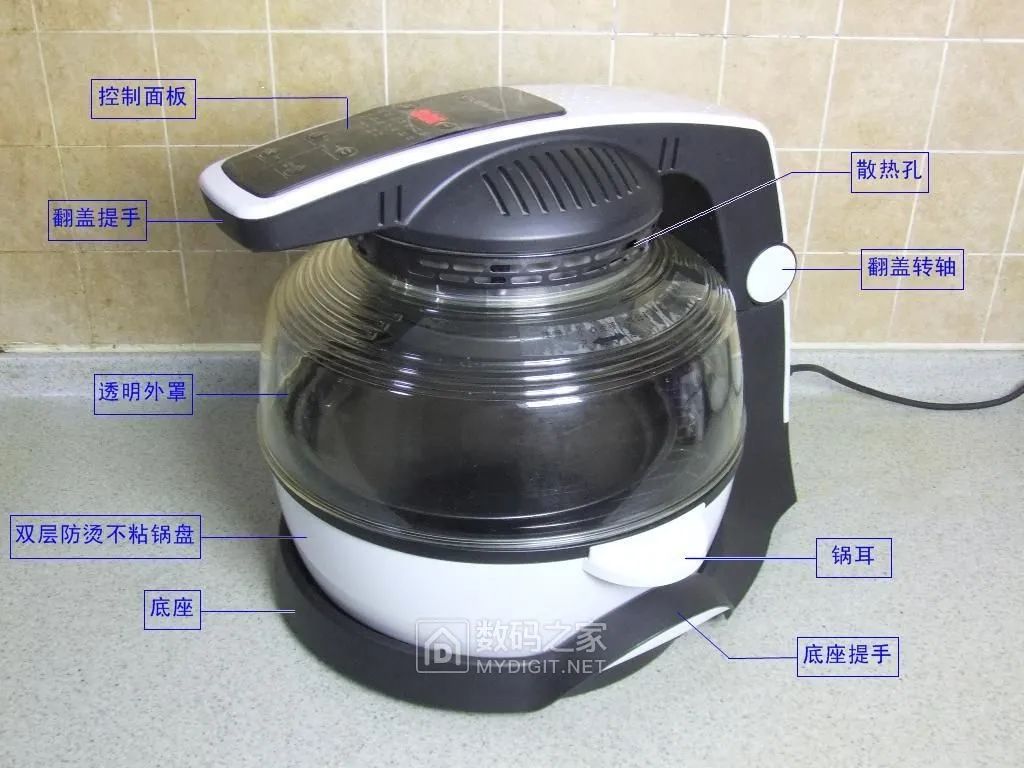
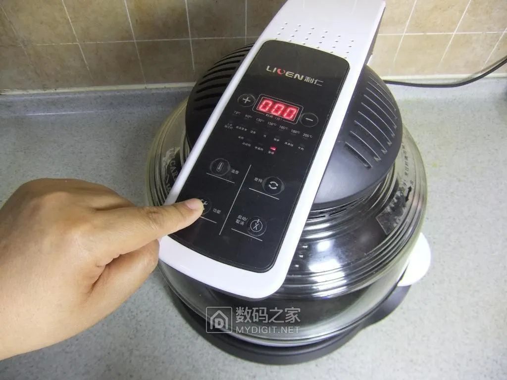
After powering on, it shows a display, but pressing any of the buttons on the control panel has no response, somewhat like it is “crashed”:
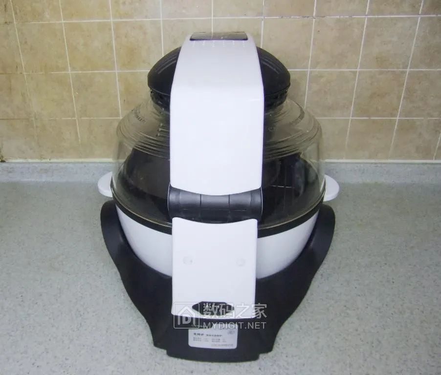
On the back of the machine, there is a power socket:
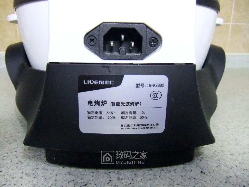
The nameplate indicates: 220V, 1200W, 10 liters capacity, model LR-KZ880, infrared heating source.
On the bottom, there are six silicone suction pads to prevent sliding when placed on the countertop:
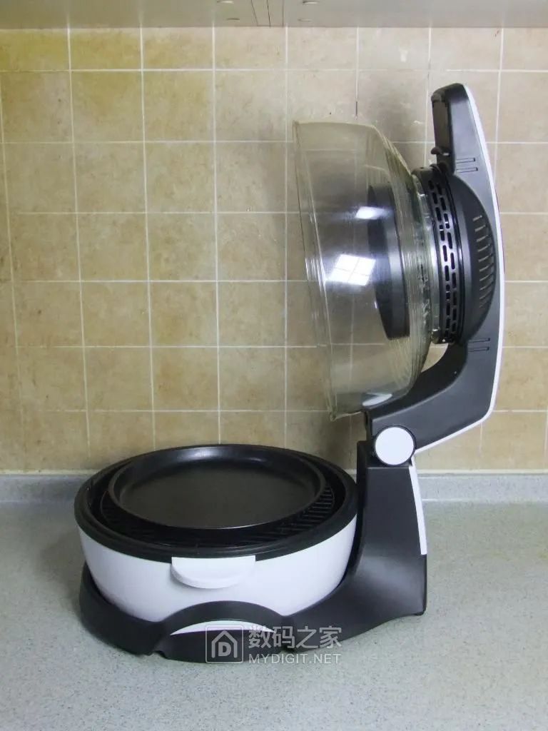
By pulling the handle upwards, the transparent cover can be opened to place food for baking:
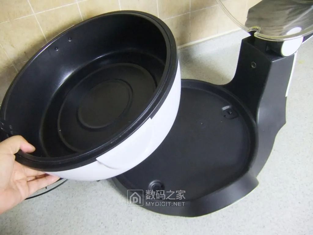
Removing the double-layer non-stick tray (the outer layer is heat-resistant plastic, and the inner layer is a metal bowl coated with Teflon, also known as an oil drip tray to catch the oil dripped from the baked food):
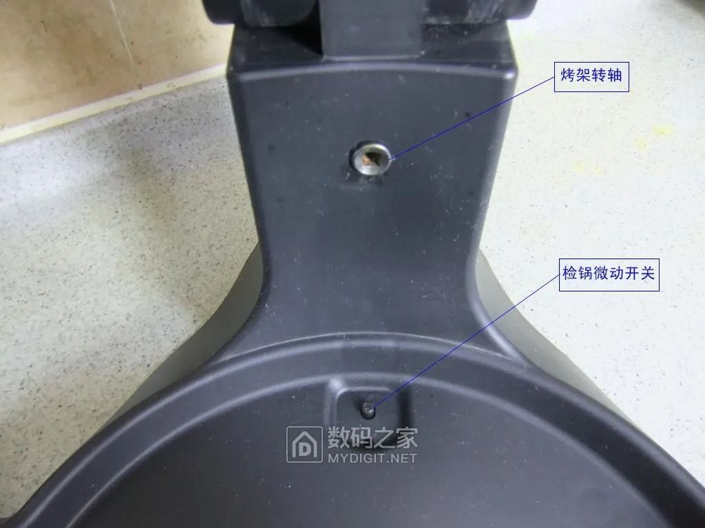
On the column, there is a shaft hole that drives the rotation of the grill. On the base, there is a micro switch that detects whether the tray (oil drip tray) is in place:
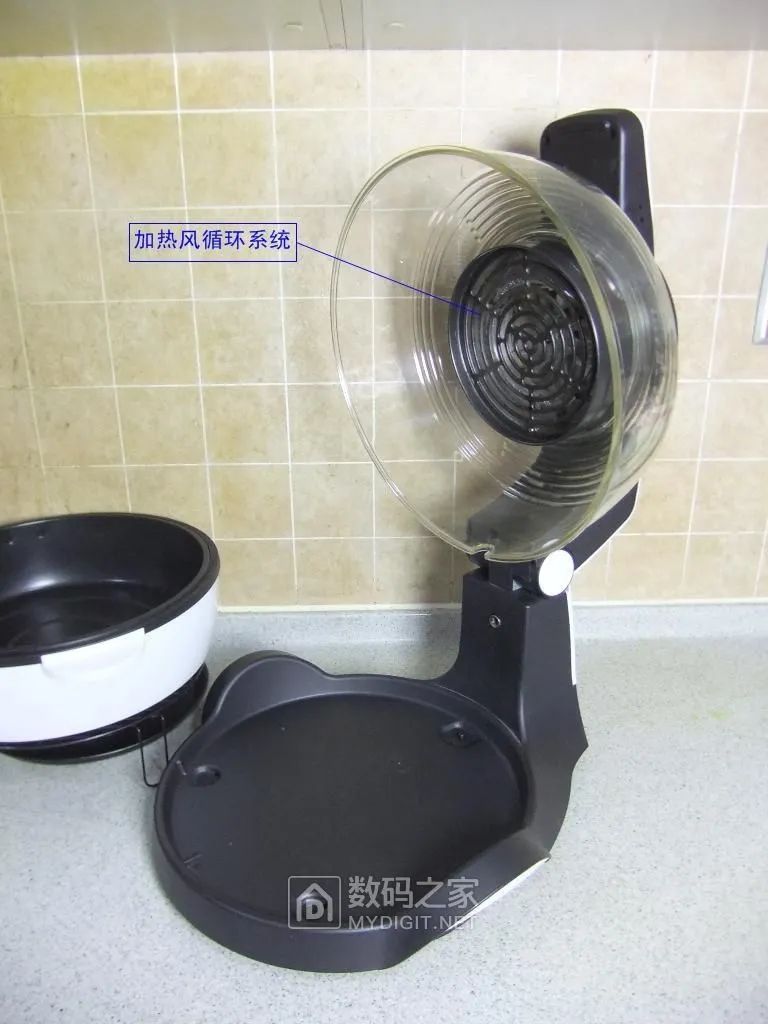
Inside the transparent cover (flap), there is a heating system:
2. Disassembly and Structure
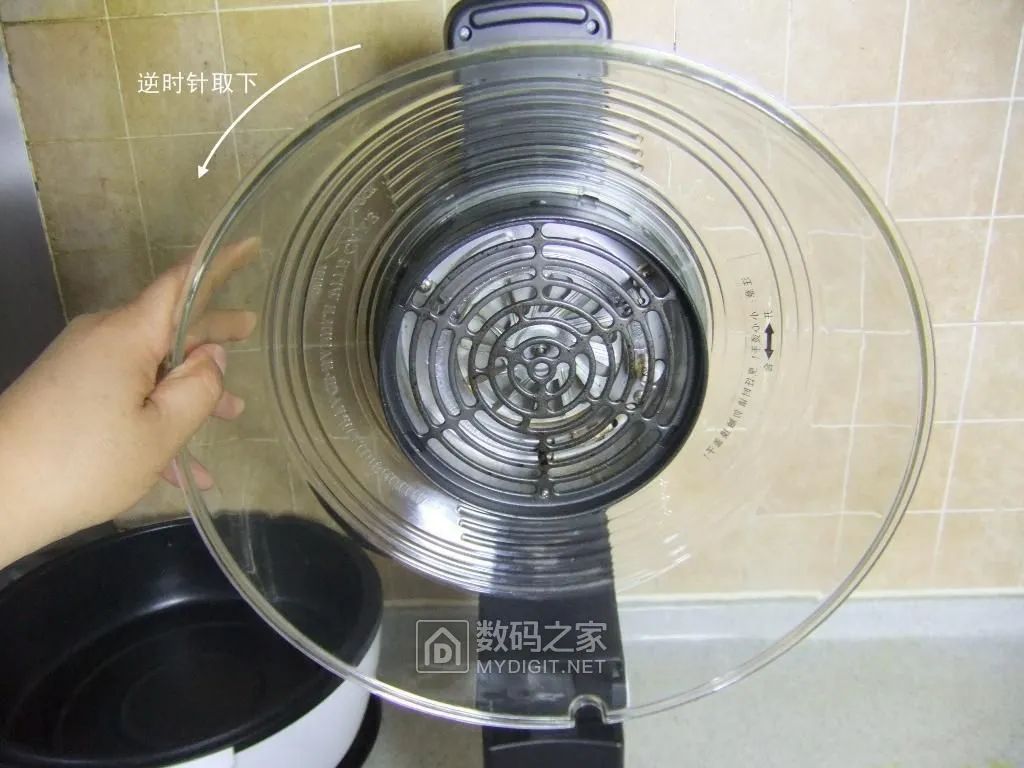
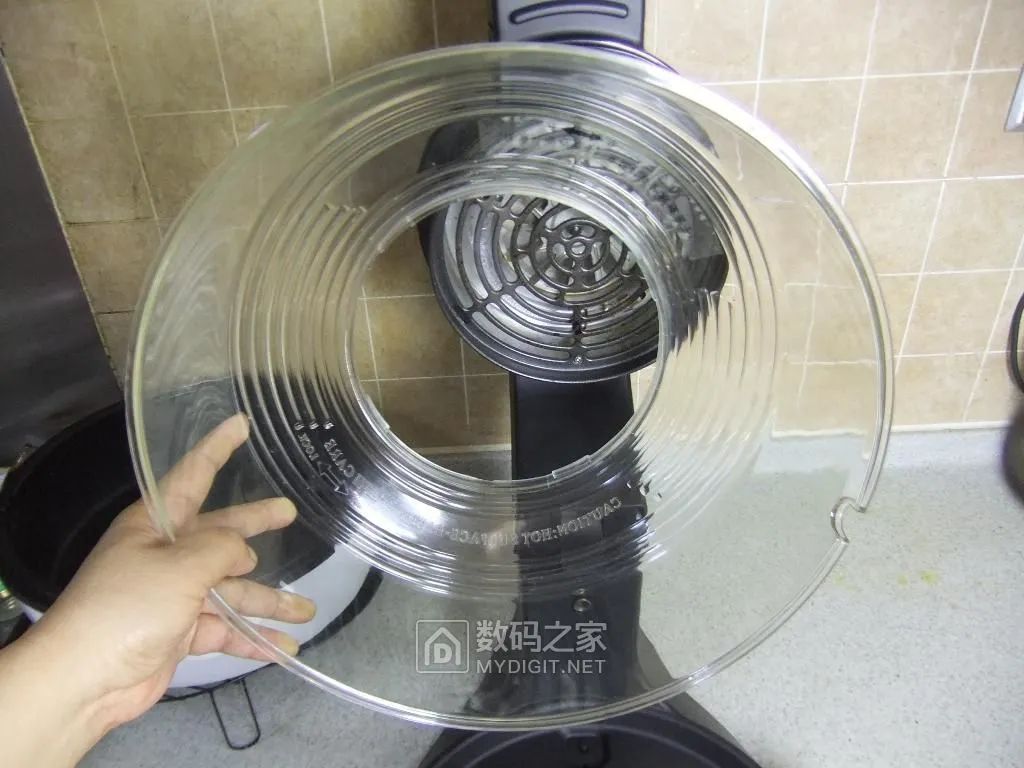
Hold the transparent cover (if it is tight, it is recommended to use both hands) and carefully rotate it counterclockwise to remove it:
The structure of the heating system: the outer part is a metal protective mesh, and inside there are infrared heating tubes and a fan.
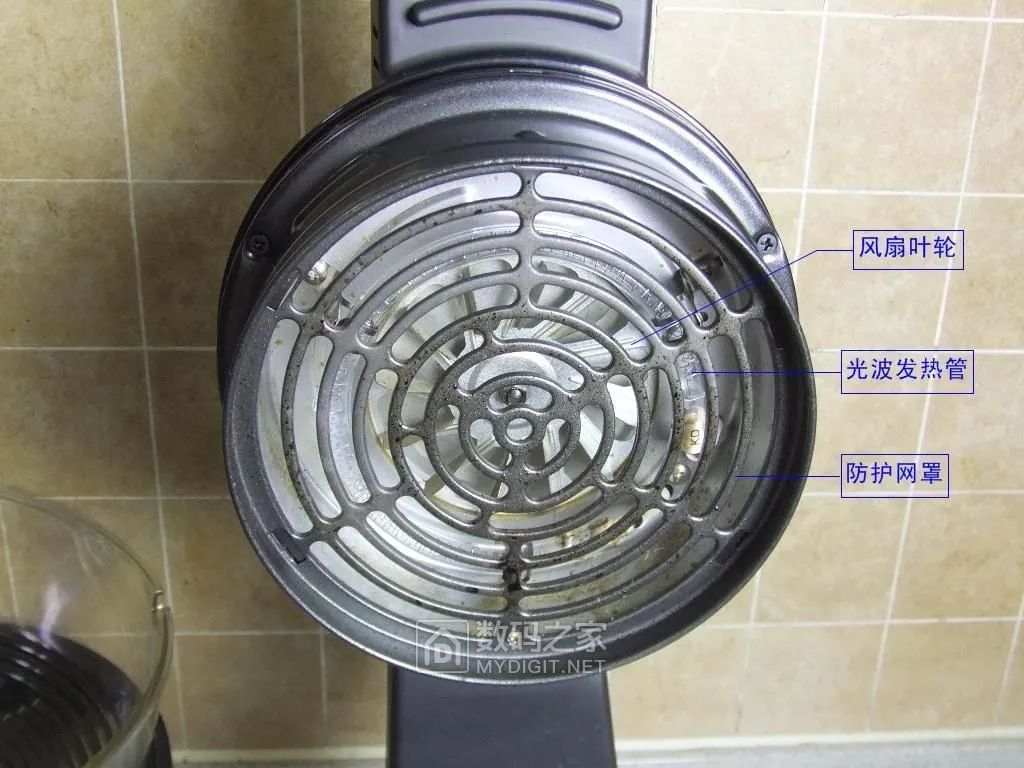
Remove a fixed screw from the lower part of the metal protective mesh:
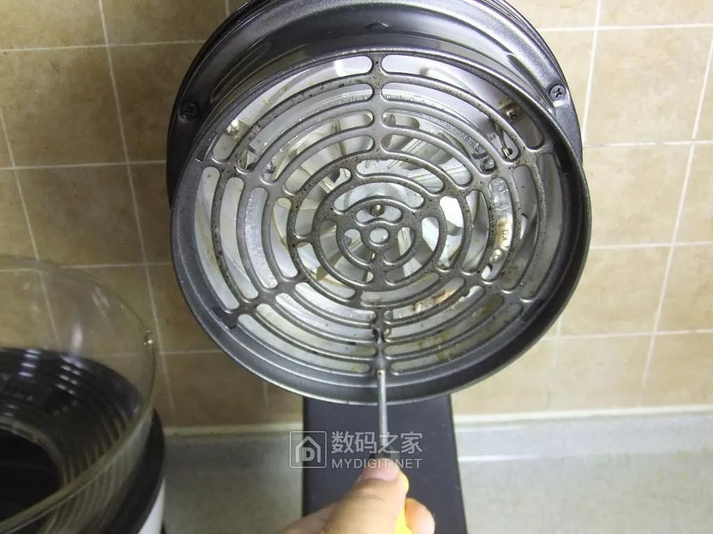
Remove the protective mesh:
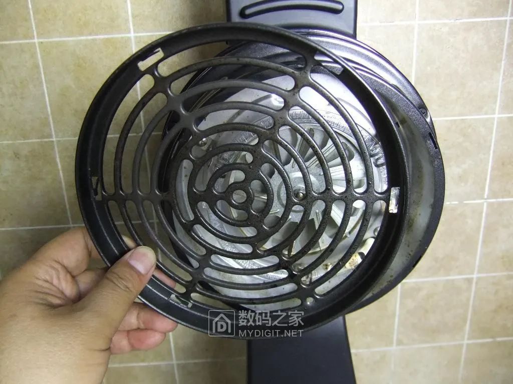
Inside are the annular infrared heating tubes and metal fan blades. Since this type of fryer is a closed type, oil smoke has a certain deposition on the inner wall and the lamp tube:
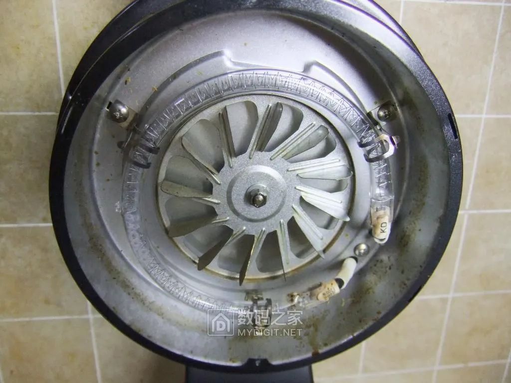
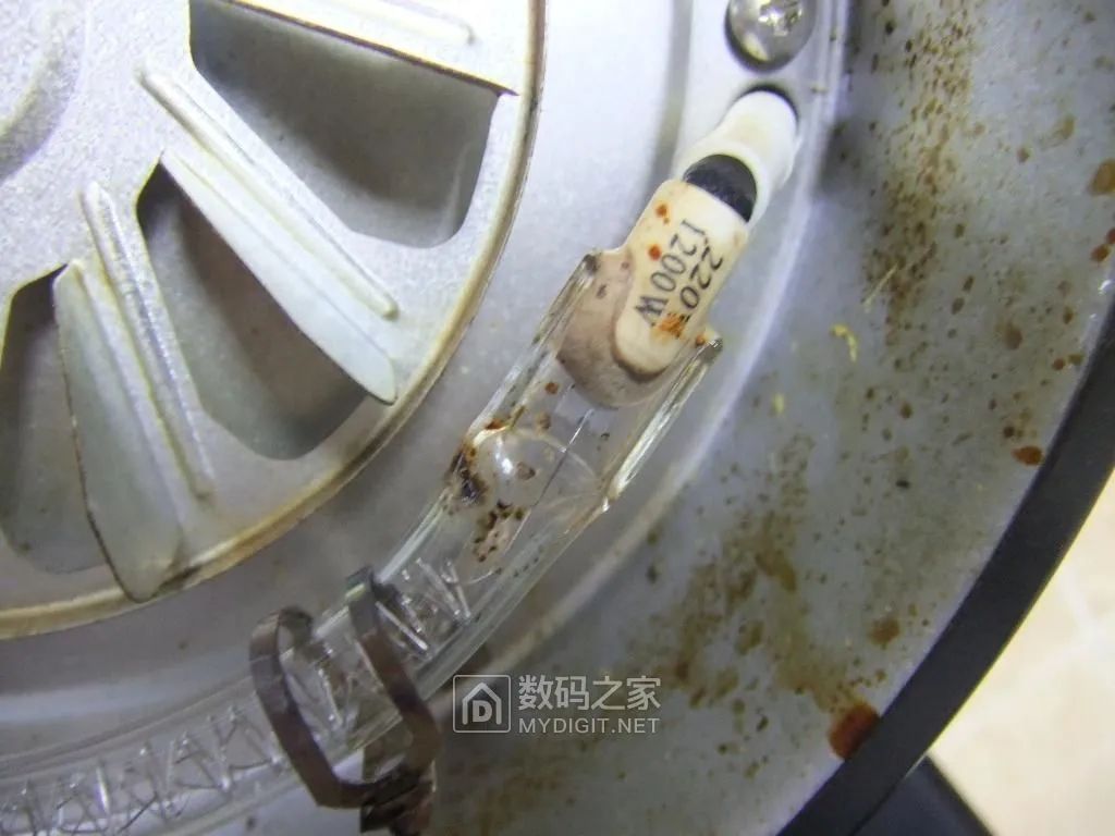
This is a 1200W infrared tube, which is actually an annular halogen lamp:
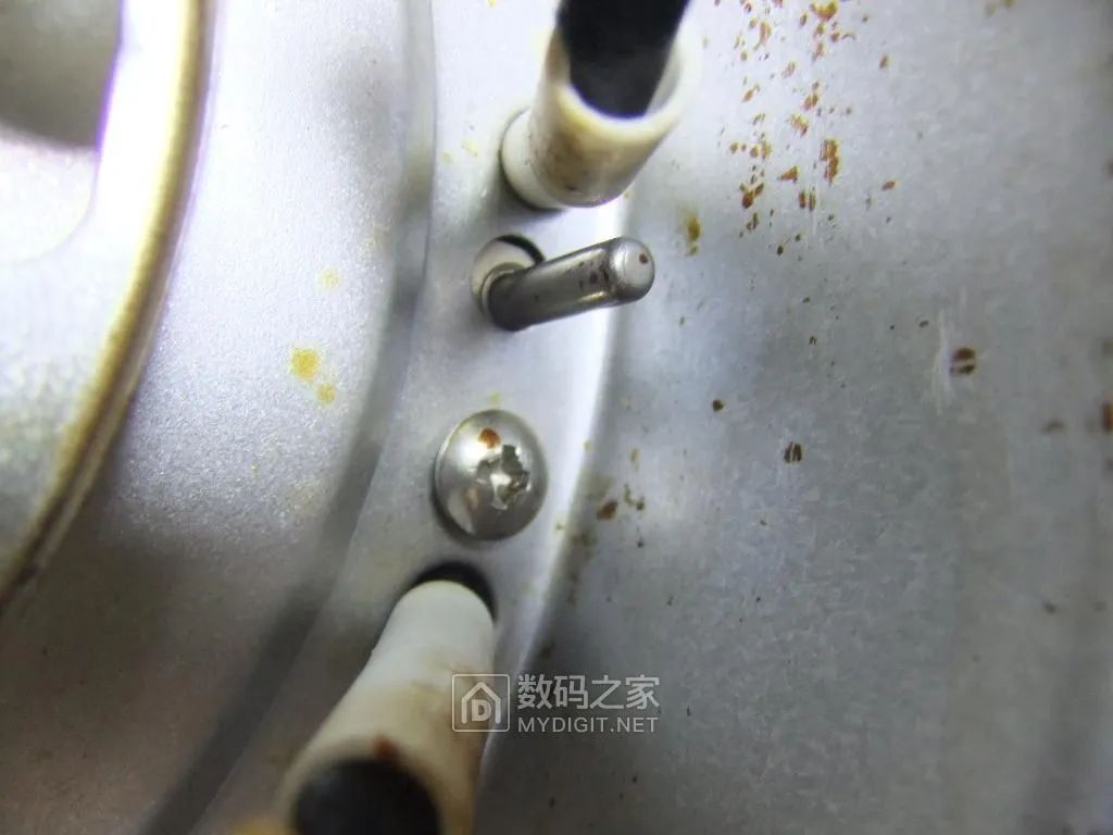
Between the leads of the infrared tube is a metal armored negative temperature coefficient resistor (room temperature 27℃, resistance 93.8KΩ), acting as a temperature sensor:
Since it’s opened, let’s clean it up as well. First, use a powerful kitchen grease cleaner:
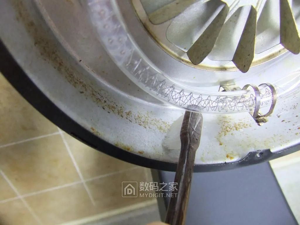
Then wipe it clean with a cloth:
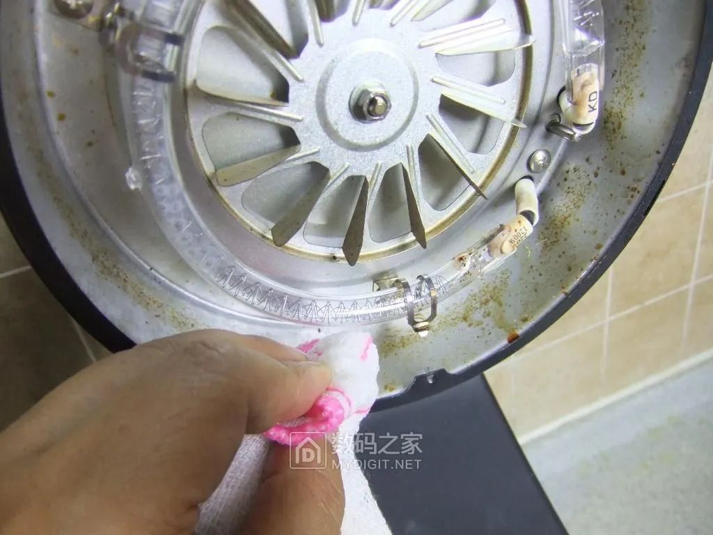
Much cleaner now:
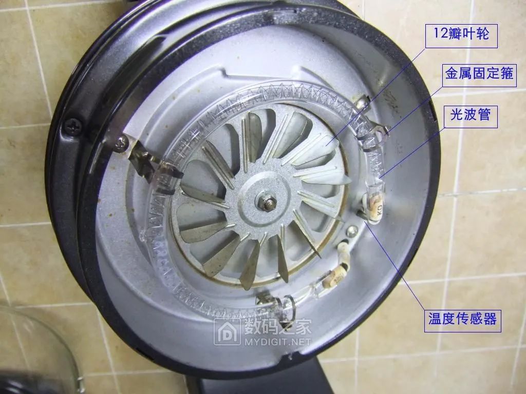
Remove the three fixed screws of the heater’s metal cover and take off the cover:
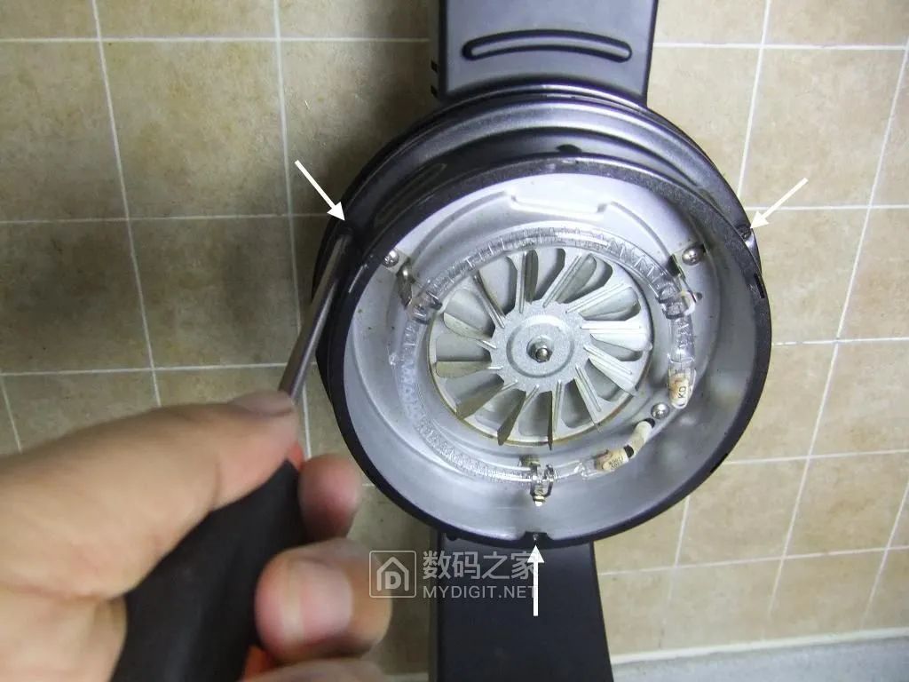
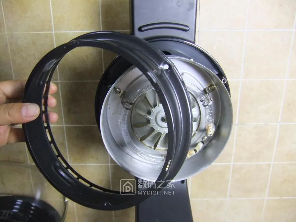
After removing the cover, we see a thermal insulation space behind the heater’s aluminum plate:
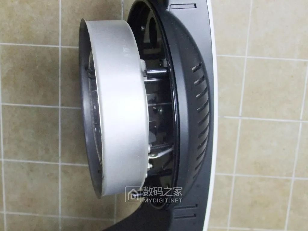
From this angle, we can see that a coaxial fan impeller is installed in the insulation space to blow out heat, preventing the handle from getting hot, while also helping to dissipate heat from the circuit board inside the handle:
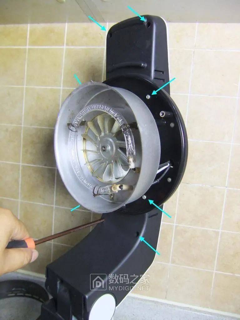
Remove the eight fixed screws on the handle:
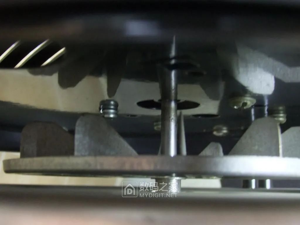
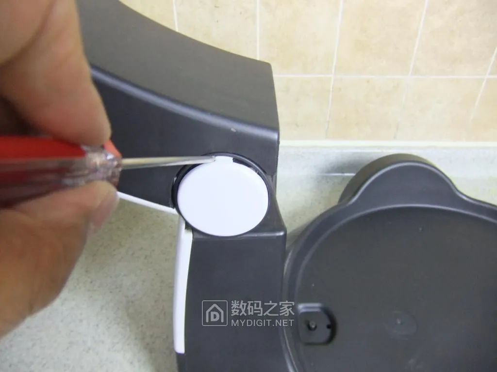
Take off the round cover plate at the pivot:
Then remove the fixed screws at both ends:
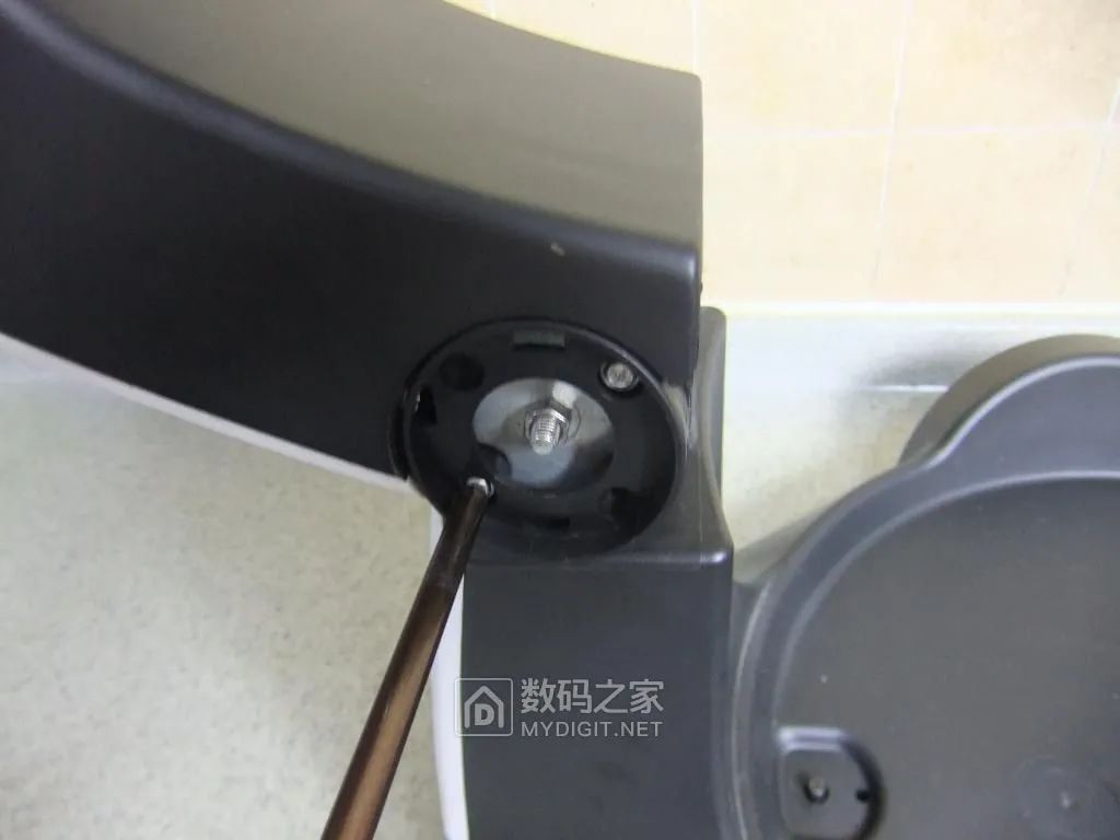
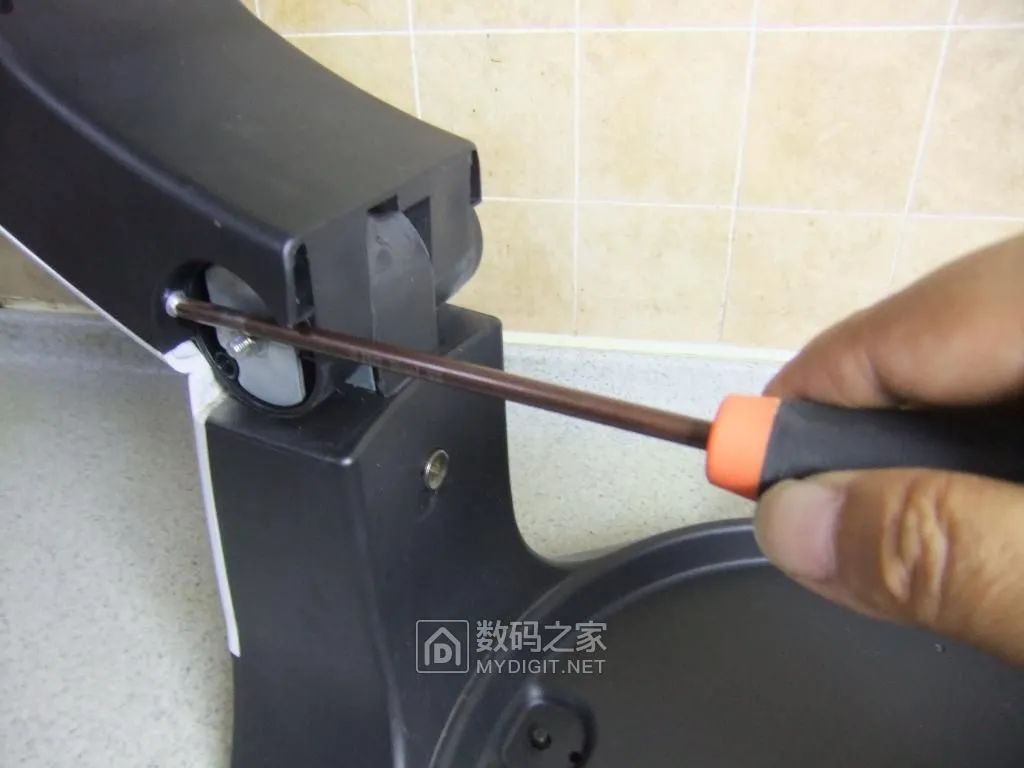
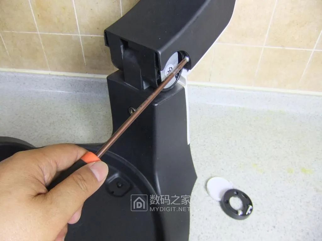
After removing all the fixed screws, the handle can be separated, revealing the internal circuit board:
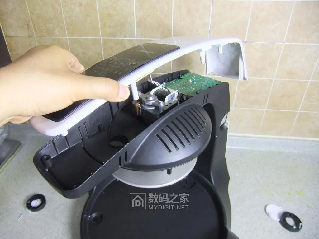
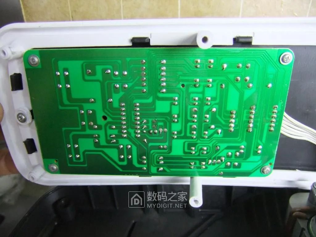
The control circuit board installed on the cover of the handle:
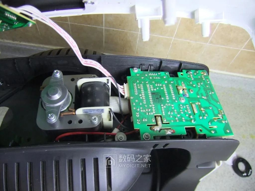
The fan motor and main circuit board installed inside the handle:
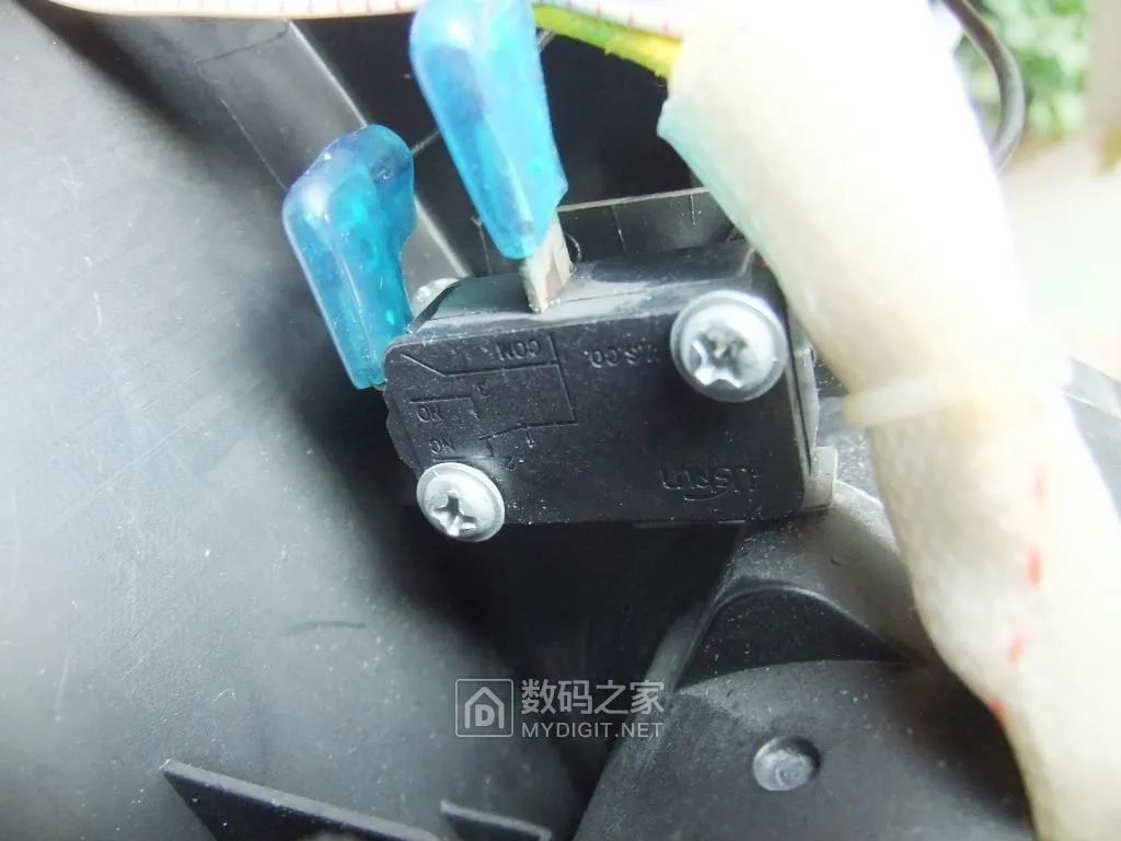
The micro switch at the pivot (when the handle is opened or closed, the contacts open or close):
Remove the cover panel on the back of the column, and the claw-type permanent magnet synchronous motor is the drive for the grill rotation:
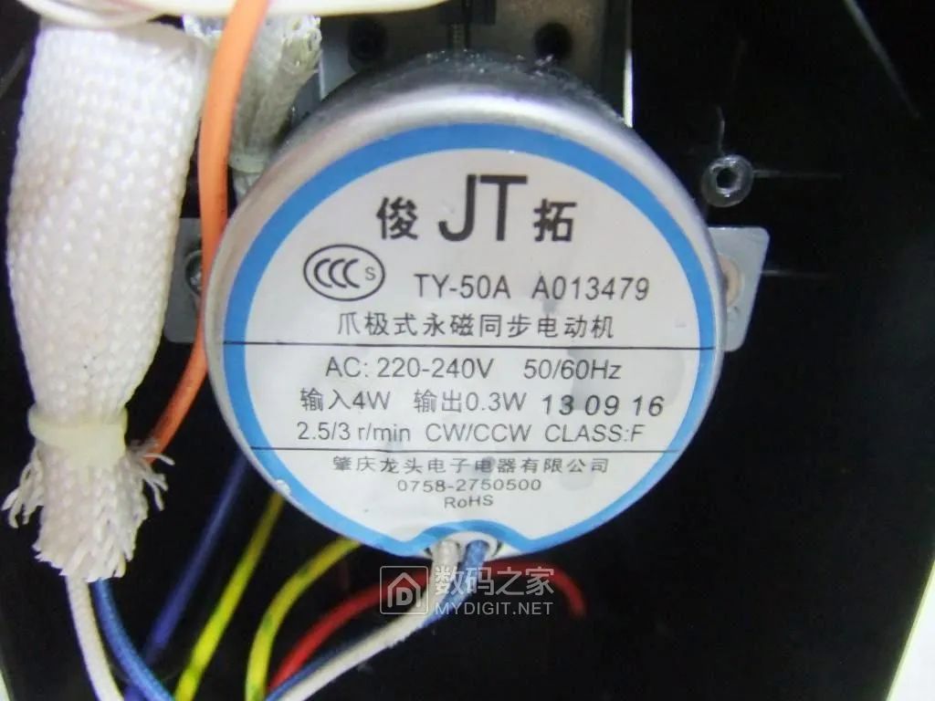
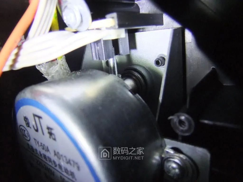
On the motor shaft, there is a photoelectric switch, and its signal is used to control whether the grill rotates continuously or on one side:
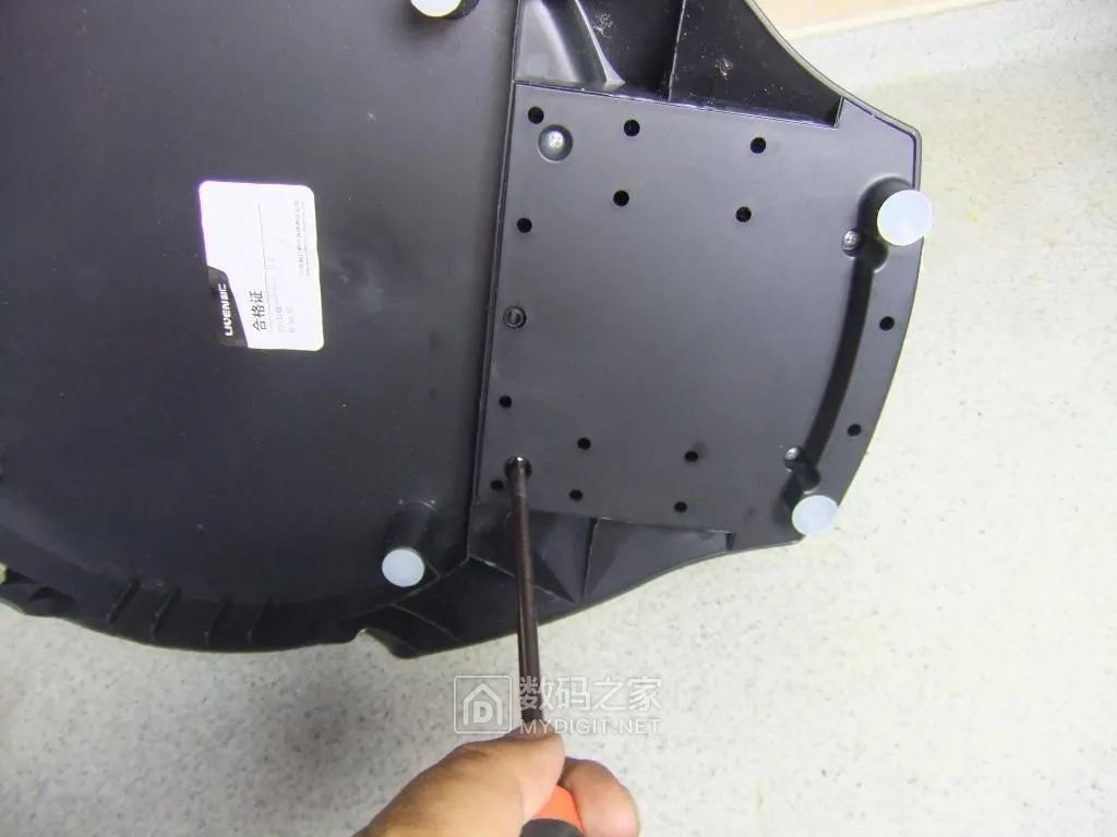
Remove the four fixed screws from the base cover:
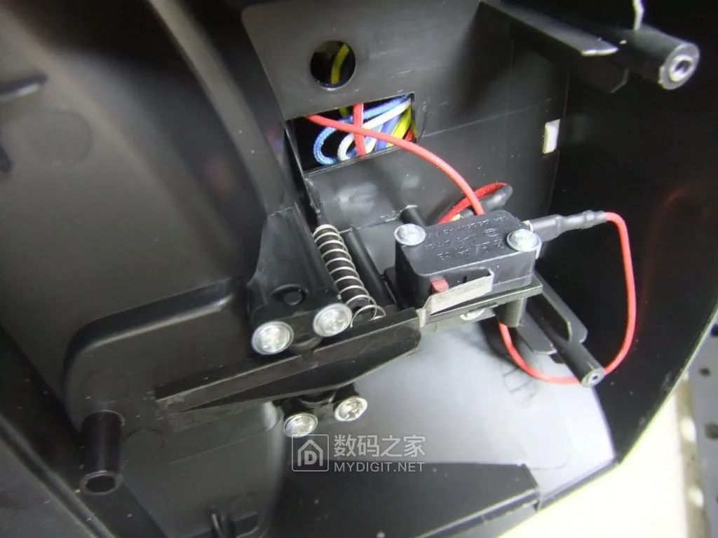
See that there is a micro switch inside:
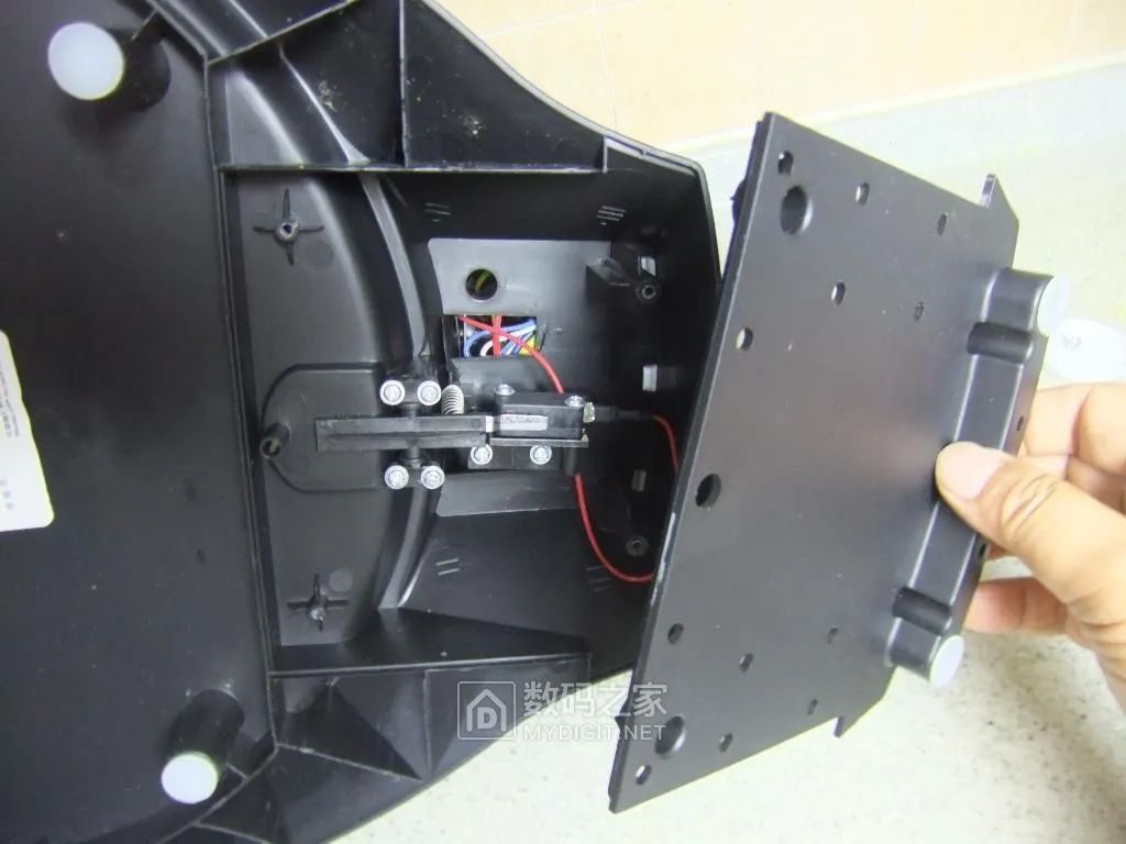
This micro switch is used to detect the placement position of the non-stick tray (drip tray):
3. Circuit Components
The fan motor uses a single-phase shaded pole motor, 220V, 4W, speed 2200r/min
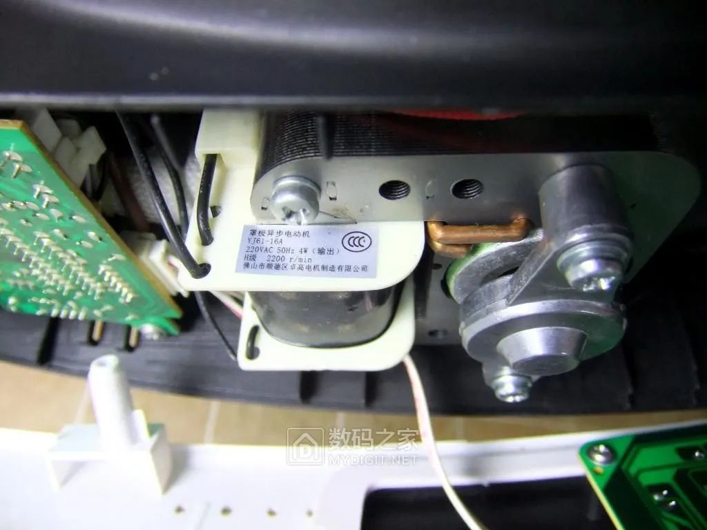
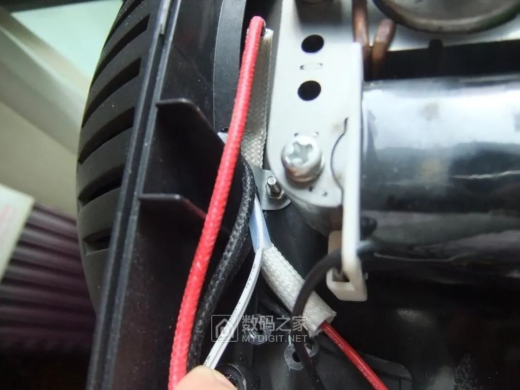
Next to the fan motor, there is a temperature fuse fixed to the iron plate, which cuts off the circuit when a temperature control failure occurs. This temperature fuse is in a narrow position, making it difficult to replace, and the temperature value is unknown:
Remove the fixed screws of the main circuit board and take out the main circuit board:
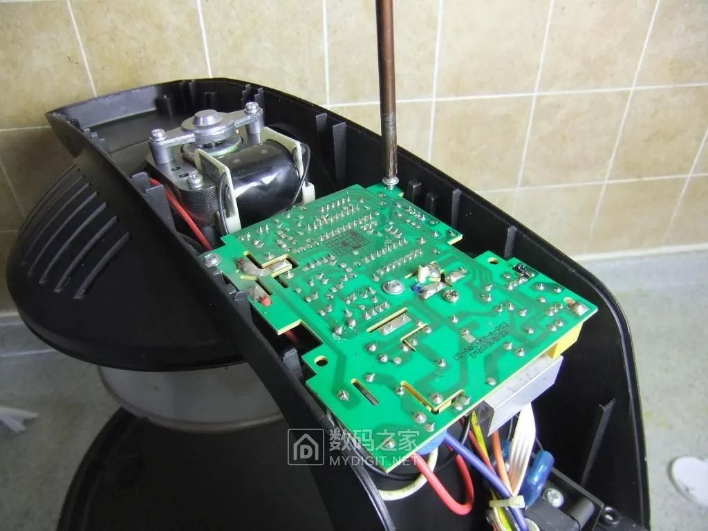
Distribution of functional areas of components on the main circuit board:
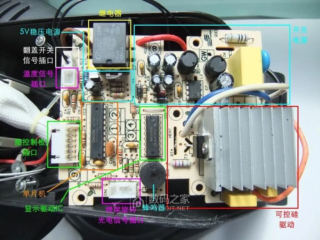
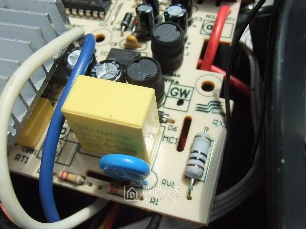
On the circuit board, RX1 is a 10Ω 2W fuse resistor, the blue round piece RV1 is a varistor, and the yellow MC1 is a safety capacitor:
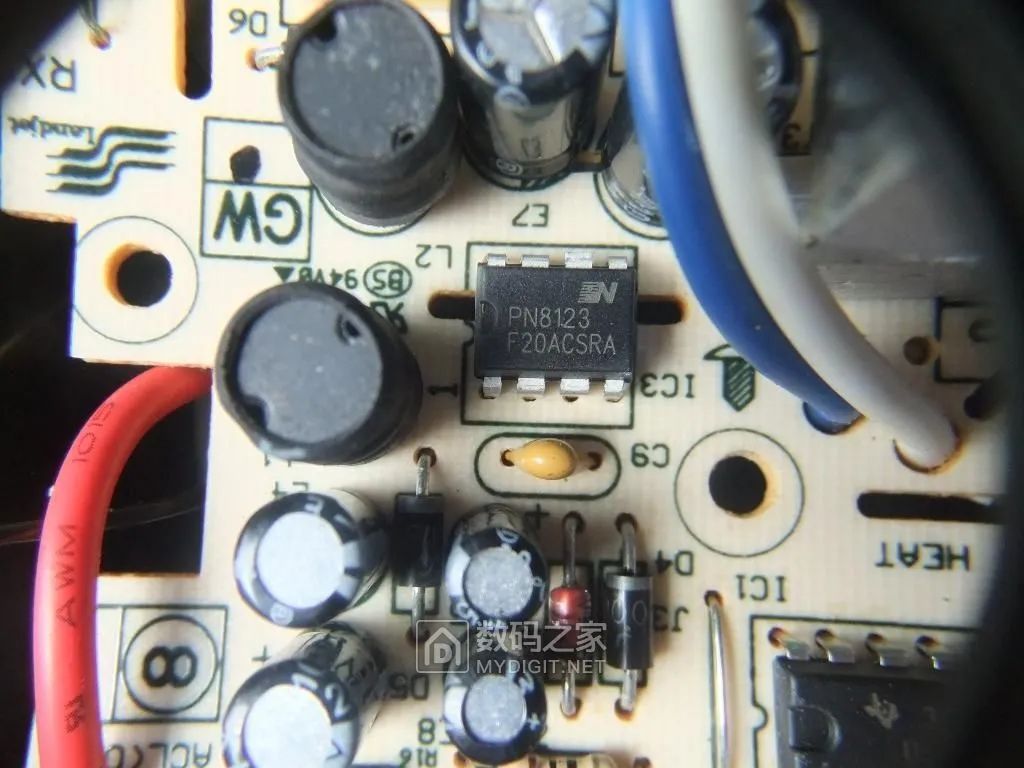
IC3 is a commonly used non-isolated power management chip for small appliances, PN8123:
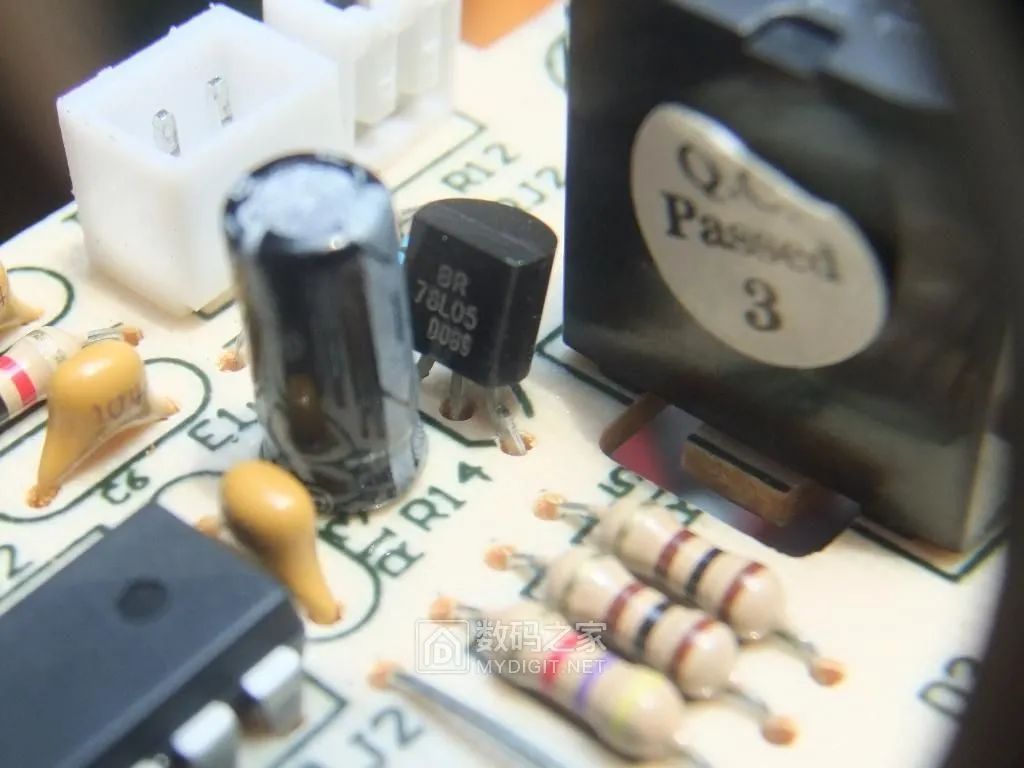
IC4 is a 78L05 three-terminal linear voltage regulator, providing a 5V regulated power supply for the microcontroller:
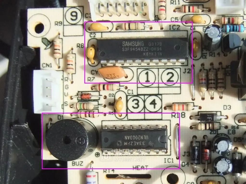
IC2 is a commonly used microcontroller in home appliances, model S3F9454BZZ-DK94, the yellow component CY1 below is a three-pin 8MHz ceramic filter; IC1 is a large current driving array integrated circuit ULN2003AN, widely used in microcontrollers, smart instruments, PLCs, digital output cards, etc., with an output of up to 500mA/50V, capable of directly driving loads such as relays, and the adjacent black cylindrical object BUZ is a buzzer.
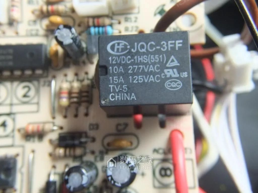
The 12V DC relay, model JQC-3FF, has a contact load of 10A 277VAC, responsible for cutting off or connecting the power supply of the infrared heating tube, fan, and grill rotation motor when the handle is opened or closed:
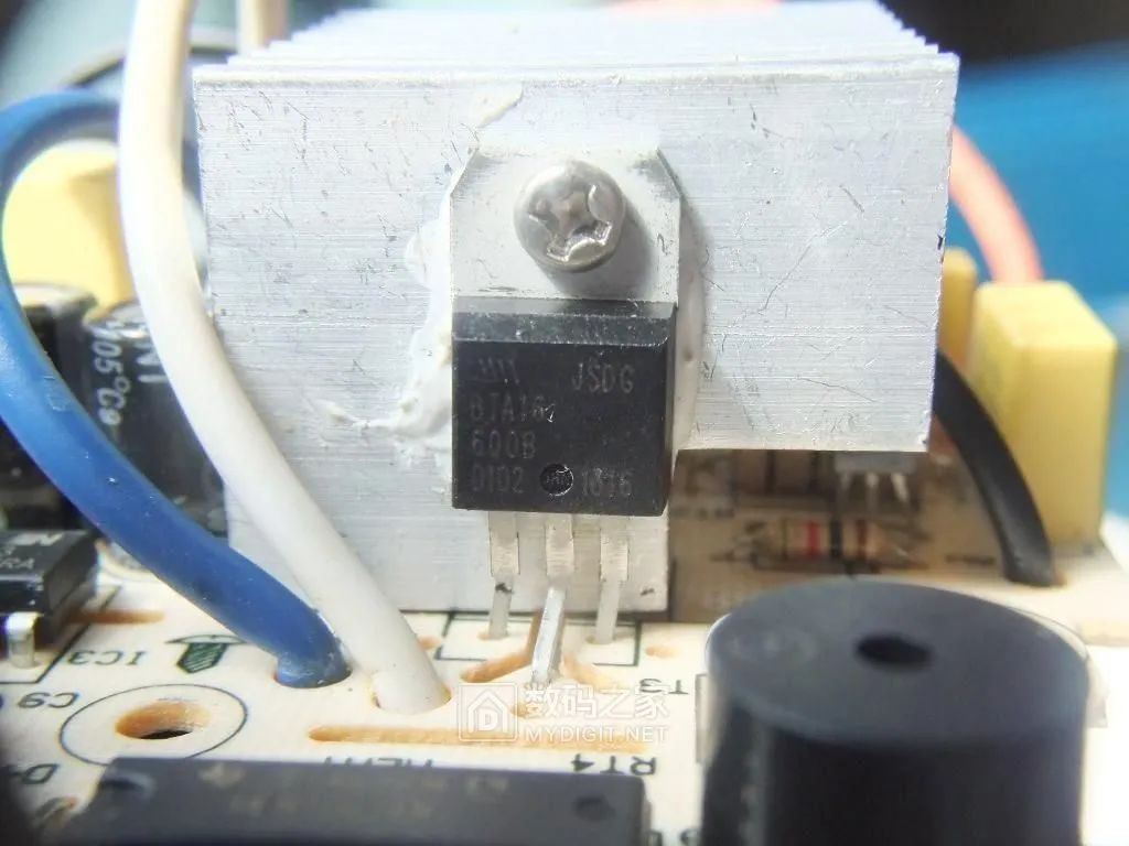
Next is the bidirectional thyristor that drives the 1200W infrared heating tube, model BTA16-600B (16A/600V). Due to the large working current and high heat generation, the aluminum heat sink is relatively large:
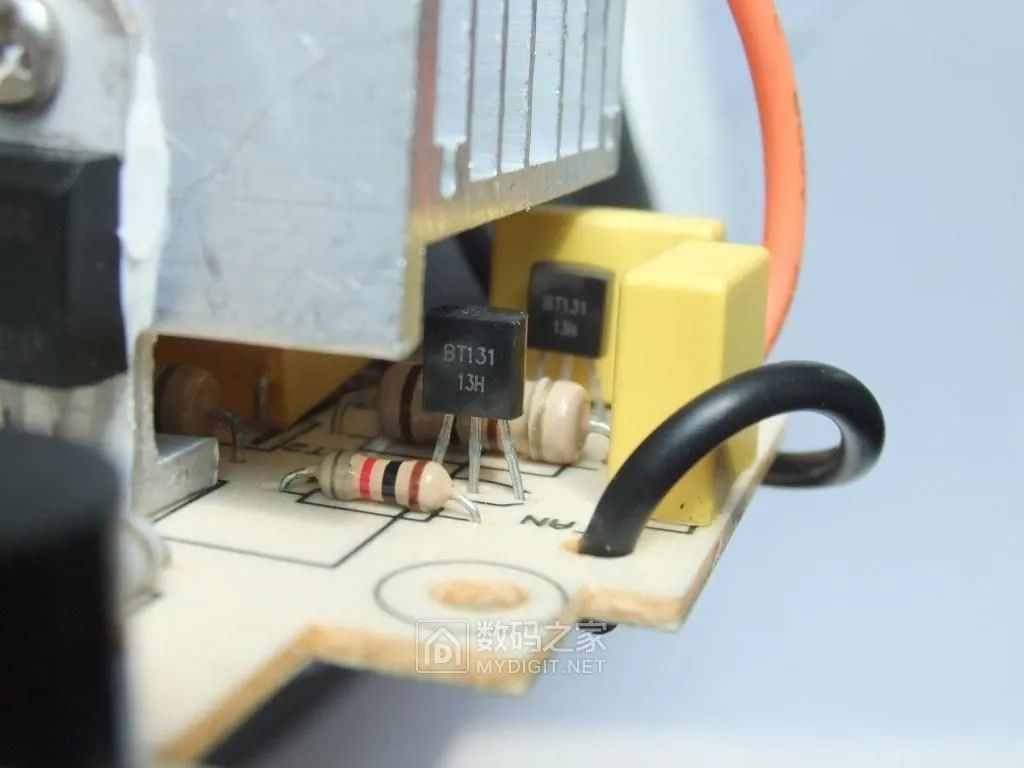
Next to the heat sink, there are two small power bidirectional thyristors, model BT31 (1A/600V), which are the drivers for the fan and grill rotation motor:
The control circuit board removed from the handle:
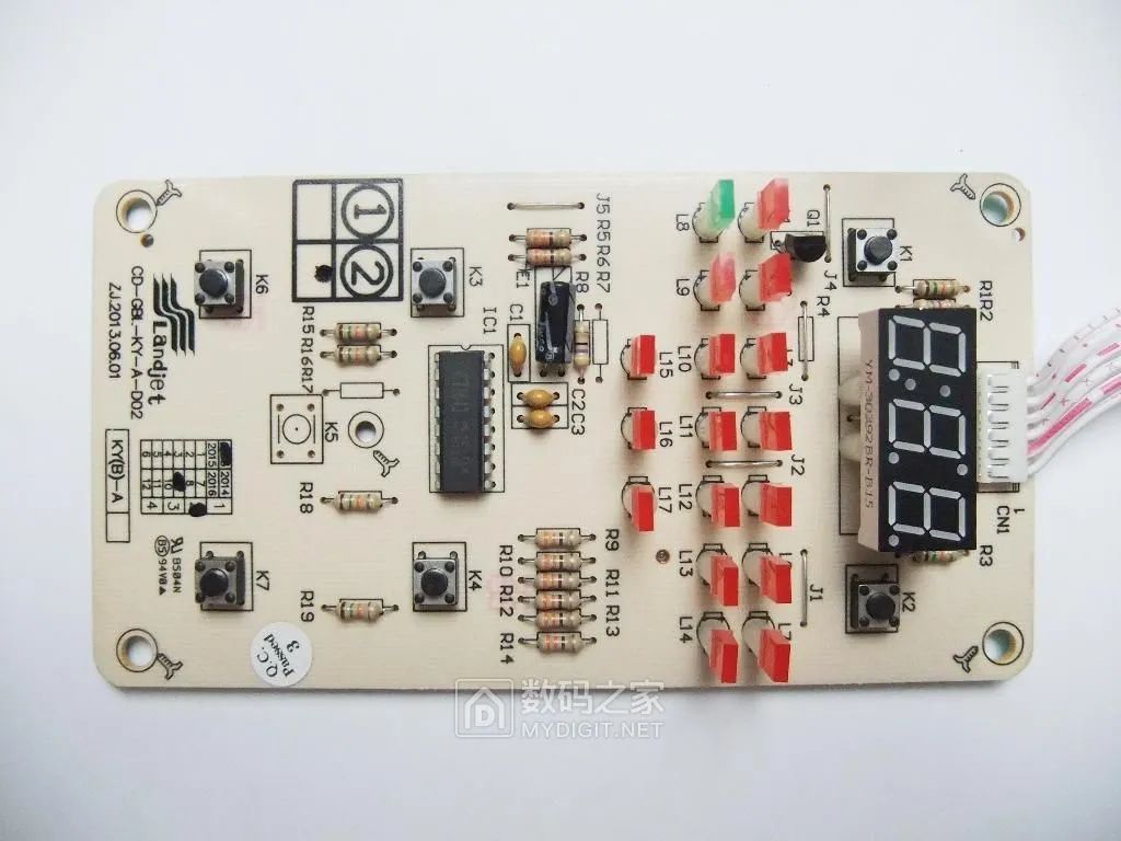
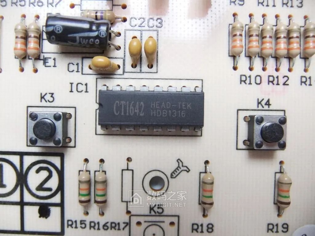
On the circuit board, IC1 is the LED digital tube drive control integrated circuit, model CT1642:
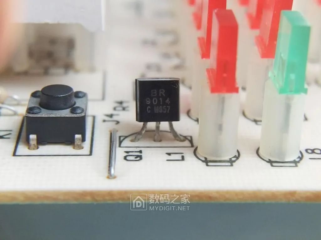
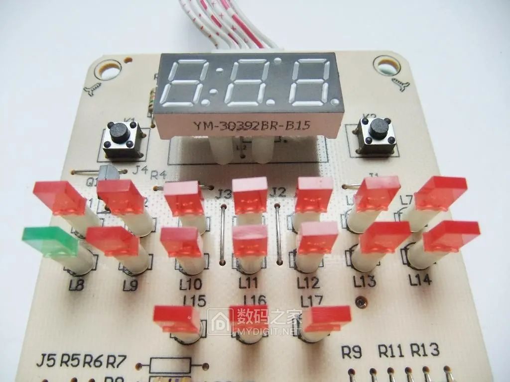
There are three LEDs (L1, L9, L12) on the circuit board driven by Q1 (9014), while the other LEDs are driven by CT1642:
4. Circuit Working Principle and Circuit Diagram
1. Circuit Principle
Based on the circuit board, the circuit principle block diagram of this air fryer is drawn as follows:
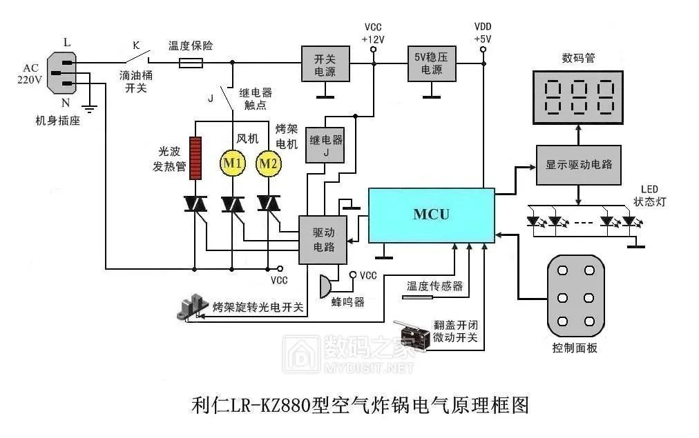
Working principle of the circuit:
After plugging in the power, only when the drip tray (pan) is placed correctly, its micro switch K is closed, can the 12V switch power supply and 5V regulated power supply work, and the control system powers up. The program performs a self-check, and when the temperature and the position of the handle are both normal, the buzzer emits a long “beep” sound, closing relay J, and the digital tube displays “000”, preparing to start the machine. Then, set the baking program on the control panel and press the “Start” button, and the machine begins to work. During baking, when the temperature reaches the set value, the microcontroller sends a command to stop heating the infrared tube; when the temperature drops below the set value, the microcontroller sends a command to heat the infrared tube, alternating continuously until the time ends. During baking, if you want to open the flap to brush some oil on the food being baked, you can directly lift the handle, and the micro switch at the pivot opens, sending a disconnection signal to the microcontroller, which issues a command to disconnect the relay, immediately stopping the operation of the infrared heating tube, fan, and grill rotation motor. When the flap is closed again, it resumes the original program to continue baking. In the circuit, the digital tube displays the time, the red LED shows the set baking mode, and the green LED is the working indicator light. The temperature fuse cuts off the power supply of the whole machine in case of exceeding the maximum temperature fault or serious short circuit fault, and normal work can only be restored after troubleshooting and replacing the new temperature fuse.
2. Circuit Diagram
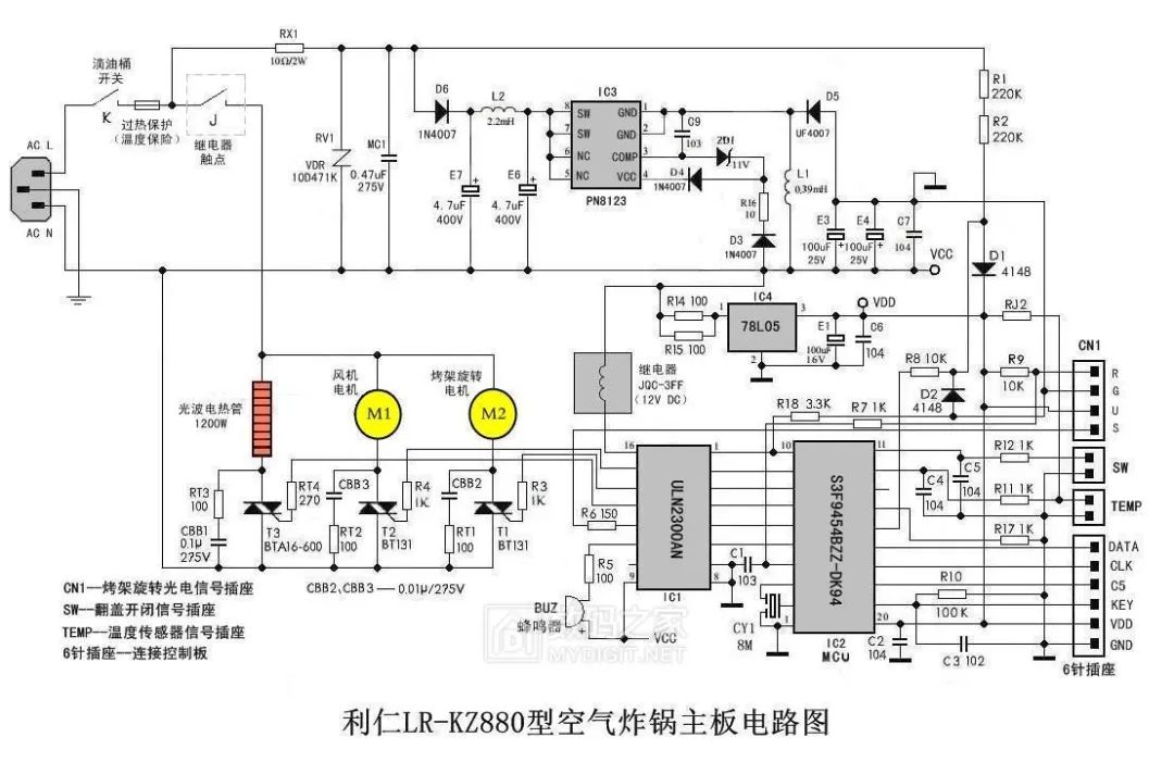
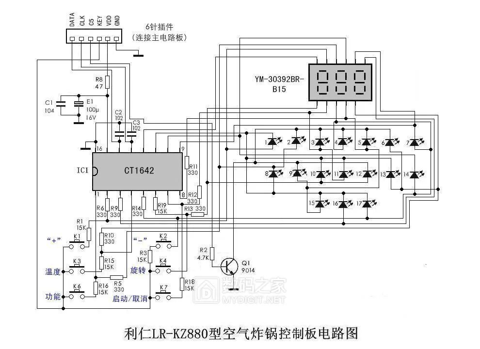
Based on the actual object, the circuit diagram is drawn as follows. It includes the main circuit board circuit diagram and the control board circuit diagram. The parameters of each component are indicated on the circuit diagram. There may be imperfections, for reference only during maintenance.
(1) The circuit diagram of the main circuit board is as follows:
(2) The circuit diagram of the control board is as follows:
5. Troubleshooting the Non-Responsive Control Panel Fault
1. Analysis and Inspection of the Fault Cause
The function of the panel buttons is shown in the figure below:
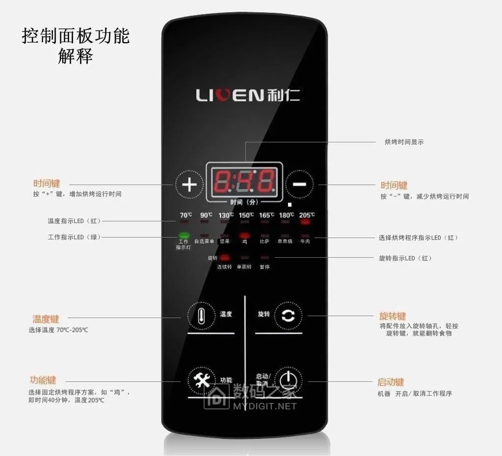
Analyze in conjunction with the circuit diagram. Under normal circumstances, when the machine is powered on and goes through self-check, only after pressing the “Function” button to select the baking program, and then pressing the “Start” button, can the machine start working. If the panel buttons are unresponsive, first check if there is a problem with the “Function” button!
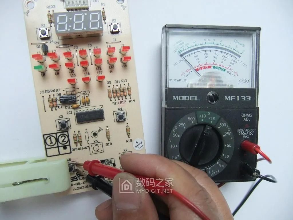
On the control circuit board, the micro switch for the “Function” button is numbered K6. Use a multimeter in resistance mode to test; when pressed, there is no continuity, indicating a problem! The other microswitches have no issues:
2. Repair the Faulty Component
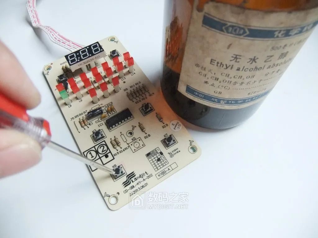
Drip some anhydrous alcohol into the gap of the K6 microswitch, repeatedly press the button (also need to hold the circuit board upright so that the liquid inside the microswitch flows down), aiming to clean the contact surface inside the microswitch:
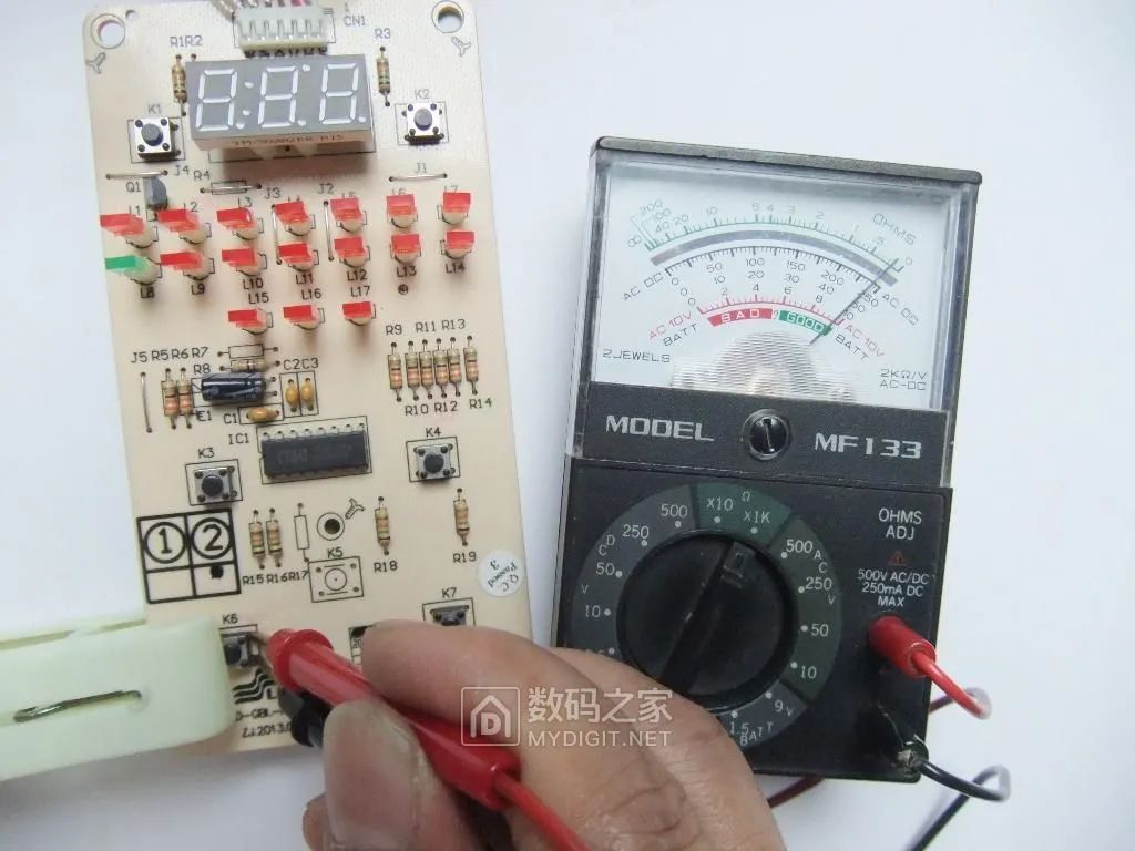
After the alcohol evaporates, test again with the meter; when pressed, it passes! To be safe, handle the other microswitches as well.
Reinstall the machine, power it on for testing, and the panel buttons respond, eliminating the fault phenomenon:
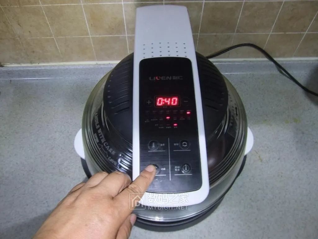
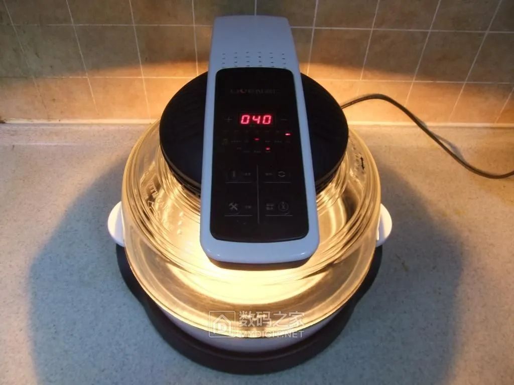
After setting the baking method, press the “Start” button, and the machine works normally. However, the light is quite strong and appears somewhat glaring:
6. Conclusion
1. The essence of the air fryer is an electric oven that circulates hot air internally. By heating and baking, it forces the oil inside the food out (some foods must be brushed with oil separately), forming a crispy exterior and tender interior, requiring a full grasp of the machine’s characteristics and food processing skills to make delicious food. Practice makes perfect; just keep practicing. Regarding infrared tube heating, although it is intuitive, I personally believe that light loss and light pollution are also existing problems.
2. Microswitch failures are a common issue in such small appliances. This is mainly because domestic manufacturers, facing fierce market competition, lower quality control standards to control production costs, resulting in products that are not durable. During repairs, one can directly address key electronic components, testing and replacing them as needed.
Source: Digital Home Author goodanytime

END
▼Previous Hot Articles Review▼2022 Drone Industry Characteristics and Trends, DJI May No Longer Focus on Drones
MEMS, Bringing a Trillion Market Value to Apple
Will the 600MHz Frequency Band Be a Golden Frequency Band?
The DPU That Went Viral Online, What Exactly Is It?
Early Microcontroller Encryption Methods
Review Center


Long press the image, scan the code for free

 Share
Share Collect
 Like
Like View
View