
In the early 21st century, phased array ultrasonic technology expanded from the field of medical imaging to industrial non-destructive testing (NDT), establishing its significant position. The industrial phased array ultrasonic testing (PAUT) system utilizes multiple independently controlled elements or channels to emit and receive ultrasonic signals.
Compared to traditional single-channel systems, PAUT can more accurately detect defects, cover a wider range, and operate more efficiently, effectively identifying safety hazards and reducing accident risks. It has been widely applied in industries such as aerospace, special equipment, petrochemical, offshore platforms, railways, power, nuclear industry, military, metallurgy, and construction.
The basic function of industrial PAUT products is to use linear beamforming (BF) technology to formulate transmission delay rules that control the excitation timing of each element, manipulating the interference behavior of ultrasonic waves in the tested object to achieve beam steering and focusing. By receiving delayed signals and electronically scanning, phased array imaging is obtained.
As testing standards continue to improve, traditional imaging methods based on linear BF can no longer meet the demands for higher sensitivity and resolution. Therefore, new imaging technologies such as Total Focusing Method (TFM), Plane Wave Imaging (PWI), and Phase Coherent Imaging (PCI) have emerged.
To overcome the limitations of traditional PAUT methods, researchers have developed various non-typical PAUT systems, including nonlinear, ultrasonic guided waves, air-coupled ultrasound, electromagnetic acoustic transducers, and laser ultrasound. These systems have expanded the connotation of PAUT and have become research hotspots in the current field of phased array ultrasonic testing.
In recent years, PAUT technology has also begun to integrate with Structural Health Monitoring (SHM) technology. Unlike traditional non-destructive testing, SHM technology focuses on long-term continuous monitoring and assessment of structural health status. The introduction of PAUT technology enhances the sensitivity of monitoring systems, effectively monitoring equipment status and providing timely warning and alarm information, supporting preventive maintenance with data.
Basic Research on Typical Phased Array Systems
01
Phased Array Signal Acquisition and Imaging Methods
Typical industrial PAUT technology mainly adopts contact or water immersion linear body wave detection methods. The elements of the probe are mainly made of piezoelectric materials, and the product forms generally include portable, board, and desktop advanced phased array flaw detectors to meet different needs. A comparison of mainstream commercial products is shown in Table 1.Table 1 Comparison Analysis of Commercial Phased Array Ultrasonic Systems at Home and Abroad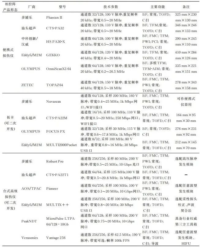 In terms of signal acquisition, the delay superposition method based on linear BF principles is the most commonly used means. Although this method can achieve efficient physical focusing or steering, it typically can only focus on a specific part inside the tested object, resulting in a significant decrease in the signal-to-noise ratio (SNR) in other non-focused areas. Therefore, the Full Matrix Capture (FMC) technology was proposed.FMC allows each element to emit signals sequentially while all elements receive signals simultaneously, thus obtaining a signal set containing N2 ultrasonic A-scan signals (where N is the number of elements). This method aids in achieving TFM imaging of the tested object during the post-processing stage.TFM is an imaging method that focuses the time-domain echo signals of different transmitting-receiving element combinations to each virtual focal point in the target area through delay superposition. The combination of FMC and TFM allows each part of the imaging area to have a high SNR.However, there is no necessary connection between FMC and TFM. For example, when Full Matrix Capture becomes triangular matrix capture, only the signals of element i transmitting and element j receiving (i≠j) are collected, while the signals of element j transmitting and element i receiving are not collected, TFM imaging can still be performed. Similarly, when Full Matrix Capture becomes diagonal matrix capture, only self-transmitting and self-receiving signals are collected, TFM imaging can still be performed according to TFM theory, and the result is equivalent to synthetic aperture focusing imaging.Additionally, sparse matrix capture is also an effective strategy, which prohibits the use of some elements to achieve sparse array TFM imaging. Studies have shown that optimizing elements through swarm intelligence algorithms can significantly reduce data volume while only slightly decreasing imaging quality.On the other hand, phase coherent imaging (PCI) and symbol coherent imaging (SCI) based on FMC have become the main research focus of commercial phased array products in recent years. PCI images based on the standard deviation of the instantaneous phase at virtual focal points, while SCI images based on the superposition of signal symbols at virtual focal points.Compared to FMC-TFM, FMC-SCI is beneficial for improving the detection capability of small defects and the SNR of coarse crystalline materials, but it is more prone to missing detection for large area defects with ultrasonic waves incident vertically, and the traditional -6 dB method cannot be used for defect quantification.FMC signals can also be used for multi-modal TFM imaging, vector TFM imaging, virtual source TFM imaging, acoustic source localization (MUSIC) imaging, phase migration imaging, scattering matrix imaging, and Omega-K imaging.In FMC, only one element transmits at a time, resulting in low energy, long acquisition time, and low imaging efficiency. The Plane Wave Composite (PWC) acquisition technology adopts a method where all elements transmit and receive simultaneously each time, forming plane waves at different angles with each transmission. For example, a phased array probe with N elements, selecting Q angles to transmit plane waves, can obtain a signal set with Q×N ultrasonic A-scan signals. Research has shown that compared to the FMC-TFM combined method, PWI can achieve images with fewer artifacts and higher SNR with less data.
02
Optimization Methods for Phased Array Measurement Processes
To achieve efficient phased array detection and monitoring, it is necessary to finely optimize the process parameters in measurement experiments. Currently, the main methods used to achieve this goal include acoustic field simulation and modeling, defect detection sensitivity distribution maps, and reliability calculations for phased array detection.First, based on the delay rules of phased array fan scanning, the acoustic field after steering and focusing can be simulated and modeled. The calculation of the acoustic field is divided into analytical methods, semi-analytical methods, and numerical methods.Analytical methods mainly include angular spectrum methods, multi-variable Gaussian beam superposition methods, ray tracing methods, and geometric diffraction theory, which have high computational efficiency but require certain theoretical assumptions and have some errors compared to reality.Semi-analytical methods mainly include Rayleigh integral methods, pencil methods in CIVA software, K-wave K-space pseudo-spectral methods, discrete point source methods, and semi-analytical finite element methods for guided waves, which can better suppress errors in off-axis acoustic fields and non-homogeneous medium acoustic fields, with moderate time consumption.Numerical methods mainly include boundary element methods, finite element methods, finite difference methods, and elastic dynamics finite integral methods. Although they take the longest time and their accuracy is greatly influenced by solvers and grids, they are suitable for complex working conditions.Through effective acoustic field simulation and modeling, parameters such as center frequency, number of elements, element spacing, wedge size, and wedge angle can be optimized, ultimately improving the coverage area or focal spot size of the acoustic field, enhancing the SNR and resolution of phased array measurements.Since TFM imaging does not involve physical beam steering and focusing, directly calculating the acoustic field has limited significance for optimizing TFM imaging. Kwan et al. quantified the spatial distribution of defect detection sensitivity in TFM imaging using Acoustic Influence Maps (AIM) to optimize detection processes, allowing virtual defects to traverse all positions on the TFM-AIM map and calculating the acoustic field and theoretical amplitude of defect waves through virtual defects and Rayleigh integral methods. Experiments showed that the TFM-AIM map for flat-bottom holes was consistent with the theory.Li Tianji et al. improved TFM-AIM into a TFM-DAC map related to defect size, which can analyze the sensitivity of different sized defects and achieve quantification with an accuracy better than 6%, surpassing traditional methods by 13%.Additionally, the Probability of Detection (POD) or SNR is also an important means to optimize phased array detection processes. Generally, the higher the SNR, the higher the POD. Bajgholi et al. compared the POD of traditional ultrasonic single probe detection, radiographic detection, phased array fan scanning detection, and phased array TFM imaging for non-destructive testing of turbine wheel weld joints, finding that TFM imaging had the highest POD, reliably detecting inclusions with a diameter of 2.5 mm.Xu et al. proposed a phased array TFM imaging method based on Compressed Sensing (CS) technology. To balance the compression ratio and SNR, a 60% compression ratio and 62.5 MHz sampling rate were optimized, achieving TFM imaging with an SNR better than 31 dB.
03
Data Analysis Methods for Phased Array Measurements
Through the analysis of phased array measurement data, full lifecycle management, material characterization, and intelligent detection/monitoring can be performed.Guan et al. conducted phased array C-scan imaging on steam turbine rotors with nearly 30 years of service, discovering a 2.1 mm long defect. They estimated the remaining safe operating life of the part based on a fatigue crack damage risk constraint method, showing that the data from phased array measurements could extend the service life by 9.4 years.Material characterization is also a research focus in the post-processing analysis of phased array data. Cao et al. used a 32-element linear array to self-transmit and self-receive in two orthogonal directions to measure the time of flight (TOF) of multiple bottom surface echoes of carbon fiber reinforced composite unidirectional pressure plates. By continuously adjusting the thickness values and sound speed values representing elastic constants in the multi-modal TOF theoretical model and particle swarm algorithm, they achieved a match between TOF and measurement results. The results showed that this method could simultaneously invert thickness and five elastic constants from measurement data, with an error better than 5%.Other studies have established a backscattering model suitable for grain shape and size evaluation using the beam steering and focusing characteristics of phased array ultrasound. By measuring the root mean square frequency spectrum of backscattering signals at different incident directions with a linear array probe, they extracted backscattering coefficients related to grain characteristics, achieving accurate inversion of grain size and shape, validated with aluminum alloy and GH4742, showing a minimum relative error of about -3.7%.Data mining and analysis of phased array detection using machine learning/deep learning is also a current research hotspot. For example, ultrasonic imaging with adaptive weight adjustment of ultrasonic signals was achieved based on convolutional neural networks; industrial defect detection automation quantification and localization were realized based on the EfficientDet object detection network; and super-resolution reconstruction of ultrasonic images was achieved based on semi-supervised cyclic generative adversarial networks.The ultrasonic team at Guangdong University of Technology proposed a sub-wavelength defect ultrasonic imaging method based on convolutional neural networks (CNN) and designed a learnable soft threshold classifier to classify the regression values of signals. The schematic diagram of the CNN detection model is shown in Figure 1. Experiments demonstrated that this method could clearly image defects of 1/5 wavelength at different depths in a strongly scattering ductile iron test block under conditions of SNR as low as 2 dB.Although deep learning has achieved success in some applications of phased array detection data analysis, there are still the following shortcomings:Large amount of data required for training;Significant influence of human labeling;Poor generalization ability of the network;Unclear physical significance of training results;Lack of physical, logical, or causal interpretability, etc. 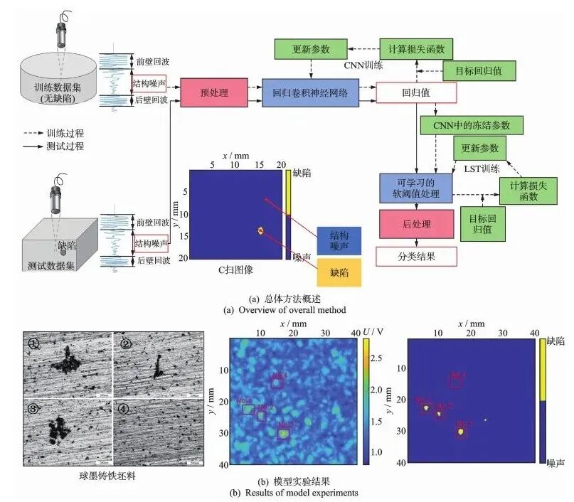 Figure 1 Schematic Diagram of CNN Detection Model
Frontiers in the Development of Non-Typical Phased Array Systems
01
Nonlinear Phased Array Ultrasonic Detection Systems
The main methods for performing nonlinear imaging using industrial phased array equipment include direct filtering, subharmonic methods, baseline subtraction, and diffusion field methods.Gao Peng et al. used a broadband phased array probe to detect carbon steel test blocks, enhancing the phased array second harmonic through phase inversion methods and directly obtaining the second harmonic using high-pass filters. The results showed that it had higher lateral and axial spatial resolution than linear BF methods.Yu et al. performed nonlinear BF imaging of polymer-bonded explosives based on Delay Multiplication and Superposition (DMAS) technology, and integrated high, medium, and low frequencies through pseudo-color technology to achieve high-precision imaging of internal defects in strongly scattering and strongly attenuating materials.In terms of subharmonic methods, Sugawara et al. proposed a confocal subharmonic phased array imaging method, obtaining subharmonics through low-pass filters, and then using delay rules to control physical focusing at each imaging point for multiple imaging and fusion, achieving imaging of closed cracks in stainless steel welds.Park et al. introduced the MUSIC algorithm to solve the problem of low resolution in subharmonic imaging, achieving high-resolution imaging of closed crack tips based on an A7075 aluminum compact tensile specimen.In terms of baseline subtraction methods, Ohara et al. performed nonlinear phased array imaging of fatigue cracks in coarse-grained 316L stainless steel test blocks through thermal modulation, mainly subtracting BF imaging maps with/without thermal stress to obtain imaging maps of crack tips, and subtracting baseline images to suppress the influence of grain noise.Haupert et al. used linear array probes for full-element BF imaging as a baseline, then selected odd and even elements for two BF imaging sessions and summed them, ultimately subtracting the baseline image to obtain nonlinear scattering imaging maps. Experiments showed that this method could effectively detect thermal fatigue cracks in 304 stainless steel materials.Ohara et al. successfully applied this method to nonlinear Rayleigh wave imaging of surface cracks. The baseline subtraction method may retain some linear features, but it is relatively easy to implement in both hardware and software, making it practical.Additionally, Potter et al. proposed a nonlinear phased array ultrasonic imaging method based on ultrasonic diffusion fields, achieving imaging of non-classical nonlinear features within materials by comparing the differences in acoustic energy under parallel physical focusing (BF) and serial synthetic focusing (FMC). Experiments showed that this method could present nonlinear features such as fatigue cracks, while linear TFM could not display crack tips and struggled to suppress the effects of upper and lower surfaces and locating holes.Cheng et al. found that nonlinear phased array ultrasonic imaging has high sensitivity for detecting fatigue crack propagation.Ebrahim-Saib et al. referred to the baseline subtraction method and diffusion field method collectively as Fundamental Amplitude Difference (FAD) technology, categorizing them into variable excitation voltage FAD, odd-even element FAD, and serial-parallel FAD (diffusion field method), and confirmed the inherent equivalence of the three through research.Despite the strong performance and multiple functions of nonlinear phased array ultrasonic FAD imaging, there are still the following issues: Lack of physical modeling and mechanism analysis to guide the further development of FAD technology; the technical applicability to complex-shaped components and thin-walled components needs further verification; currently, there is a lack of FAD imaging research for special phased array probes (such as flexible probes); and there is also limited research on the intelligence of FAD imaging.
02
Ultrasonic Guided Wave Phased Array Detection Systems
Research shows that using industrial phased array equipment to excite ultrasonic guided waves can conduct large-scale detection of waveguide structures. One study measured the high-order Lamb waves of a single mode in a 10 mm thick aluminum plate based on two 128-element linear arrays at a frequency-thickness product of 20 MHz·mm, exploring the phased comb excitation issue and establishing a Lamb wave field model, successfully exciting a single S3 mode, which is of significant reference value for detecting defects in large-sized medium-thick plates.Yuan et al. measured guided waves based on the dispersion curve of circumferential Lamb modes (CLT) in thin-walled pipes at center frequencies of 0.4 MHz·mm and 100 kHz, controlling CLT steering and focusing with a 7-element PZT array. Experiments measured 4 mm thick 6061 aluminum alloy thin-walled pipes with different curvatures, achieving a positioning error of about 5% after eliminating the influence of CLT1 using the baseline subtraction method.Li et al. collected full matrix echoes of S0 modes in 2 mm thick aluminum and steel plates using a 9-element PZT array, achieving imaging by combining TFM and phase coherent factors through phase multiplication. The results showed that this method improved resolution and suppressed artifacts compared to symbol coherent factors, with background noise 25% to 50% lower than TFM imaging.In recent years, Frequency Controlled Array (FDA) technology has become a hotspot in ultrasonic guided wave phased array detection research. Lang et al. introduced FDA technology into Lamb wave phased array detection, achieving beam steering and focusing by setting slight frequency deviations for different channels, thus obtaining high-resolution multi-frequency BF imaging maps. The schematic diagram of FDA imaging is shown in Figure 2. The study derived a weighted superposition model of wavefronts, comparing wavefront models when frequency is fixed (equivalent to single-frequency phased array), increasing, and decreasing, determining that Lamb wave steering and focusing can be controlled through frequency, allowing wavefronts to focus at the same position, proposing a frequency-increasing/decreasing fusion frequency-controlled array BF imaging method. Experiments used a 9-element PZT array to detect 2 mm aluminum plates with through holes using A0 mode waves at frequencies increasing and decreasing by 6 kHz for BF imaging, subsequently multiplying to obtain fusion imaging results, verifying stronger defect recognition and anti-interference capabilities than single-frequency BF.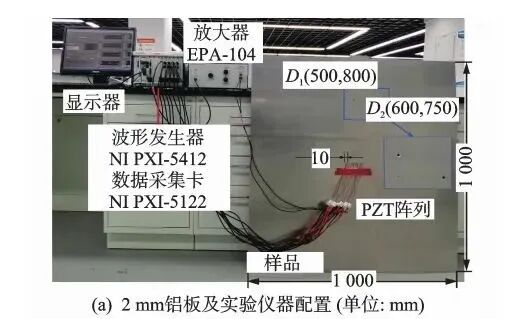
 Figure 2 Schematic Diagram of FDA ImagingDespite the development of ultrasonic guided wave phased array detection systems, there are still the following issues: the long-distance detection capability in complex media, complex shapes, and complex defects needs improvement; the practicality for thin-walled components with varying thickness, waviness, and roughness still needs verification; and there is limited research on nonlinear modulation, nonlinear mixing, and nonlinear imaging of guided waves using industrial phased array equipment.
03
Air-Coupled Ultrasonic Phased Array Detection Systems
Air-coupled ultrasound combined with phased array technology can conduct non-destructive testing under non-contact conditions, controlling steering and focusing to overcome the issues of significant attenuation and low transmission energy of ultrasonic waves in air.
Hinrichs et al. built an air-coupled phased array system based on a micro-electromechanical system (MEMS) microphone array using field-programmable gate arrays (FPGA), enhancing acoustic energy and protecting the probe with a self-made wedge. This system can excite A0 mode and S0 mode Lamb waves at 40 kHz, using a laser Doppler vibrometer (LDV) to collect signals for detecting surface groove defects in 1 mm thick steel plates. The results showed that at a maximum distance of 800 mm, the average positioning error for groove defects was 1.39 mm.
Hinrichs et al. studied the finite element simulation methods for air-coupled Lamb wave phased arrays and optimized detection process parameters. By exciting plane waves with different delay rules, they simulated mode conversion, Lamb wave leakage, and groove defect reflection behaviors, finding that the optimal pointing angle was 37.5°, close to the measured value of 34.3° from LDV, validating the accuracy of the simulation.
Laub et al. improved the above system, using an 8×8 microphone array to emit 40 kHz deflected Lamb waves to a 1 mm thick steel plate, and a 16×4 microphone array to replace LDV for receiving defect echoes, then using the MUSIC algorithm for imaging. Experiments showed that the MUSIC algorithm still performed well when considering element inconsistency.
Towlson et al. used a 40 kHz MEMS microphone array for air-coupled detection inside pipelines, mounting it on a crawler robot to inspect issues such as pipeline blockages, holes, joint failures, corrosion, and deformation. The pipeline detection robot based on air-coupled ultrasonic phased arrays is shown in Figure 3. A Monte Carlo optimization algorithm was used to obtain a random array probe with 64 elements, controlled by a Raspberry Pi 4, mini dual-channel oscilloscope/arbitrary waveform generator, and multiplexing module to acquire FMC signal sets for three-dimensional TFM imaging, ultimately achieving efficient and accurate detection and localization of internal blockages or surface conditions in pipelines at low cost.
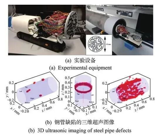 Figure 3 Pipeline Detection Robot Based on Air-Coupled Ultrasonic Phased ArrayPiezoceramic micro-machined ultrasonic probes (PMUT) and capacitive micro-machined ultrasonic probes (CMUT) arrays are also important directions for air-coupled phased array detection.Xu et al. proposed a multi-frequency PMUT array combined with CS technology to achieve three-dimensional sparse imaging. Zhang et al. manufactured a 16-element CMUT phased array probe, achieving non-contact Lamb wave excitation and reception through FPGA, capable of identifying, locating defects, and predicting defect sizes.However, air-coupled phased array ultrasonic systems are still generally limited by issues such as impedance matching difficulties, low detection frequencies, significant attenuation, and weak transmission capabilities, and their intelligence and miniaturization also need to be enhanced.
04
Electromagnetic Ultrasonic Phased Array Detection Systems
Electromagnetic ultrasonic detection systems generate ultrasonic waves non-contact within materials through electromagnetic acoustic transducers (EMAT) for non-destructive testing.Thon et al. used two curved 20-element EMAT linear arrays (with a bandwidth of 175-475 kHz and an element spacing of 4.3 mm) to measure the thickness of steel pipes. This linear array formed a 9° self-focusing curve, with adjacent elements magnetized in opposite directions. In the experiment, they first excited SH1 and SH2 mode guided waves in the steel pipe by controlling the linear delay increments between elements; then, they performed a two-dimensional Fourier transform on the echo signals, determining the cutoff frequency at the maximum amplitude drop of 20 dB on the dispersion curve, converting it into thickness values; finally, they prepared artificial corrosion defects with remaining thicknesses of 6-7.2 mm, with maximum thickness errors of 0.4 mm and 0.2 mm measured by the two modes.Zhang et al. invented a Phased Array Fully Flexible Rayleigh Wave EMAT (PAFR-EMAT) for detecting aluminum pipes with an outer diameter of 80 mm and an inner diameter of 120 mm. The schematic diagram of the phased array fully flexible Rayleigh wave EMAT detection is shown in Figure 4. In the experiment, a self-focusing flexible racetrack coil was used in conjunction with a long pulse to generate a bias magnetic field, replacing permanent magnets, and two flexible twisted coils excited 1 MHz Rayleigh waves according to delay rules. The experiment showed that when using PAFR-EMAT technology to detect 2 mm deep grooves on steel pipes, the defect wave amplitude was 4.52 times higher than that of traditional permanent magnet EMAT, and 68.1% higher than that of single-element FR-EMAT.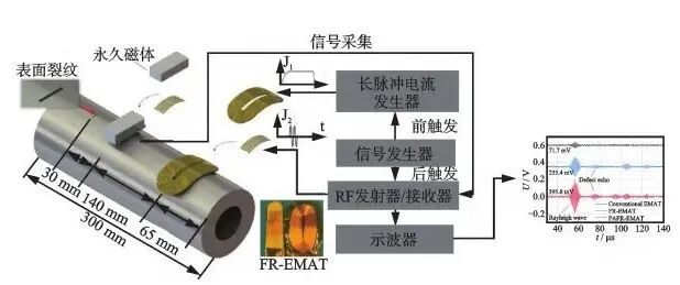 Figure 4 Schematic Diagram of Phased Array Fully Flexible Rayleigh Wave EMAT DetectionIn addition to defect detection, non-contact material property characterization is also a research hotspot in EMAT phased array measurement. Pei et al. proposed a phased EMAT based on dual twisted coils to measure the critical refractive longitudinal wave (LCR), finding through simulation that after optimizing the delay amount, the minimum diffusion angle could be 18°, reducing grating lobes. Experimental results were consistent with simulations, indicating that this method can effectively excite high-directionality LCR waves, with high sensitivity for acoustic time and stress measurements.Liu et al. used a circular EMAT phased array to measure the Rayleigh wave velocity in the friction stir welding zone of rolled aluminum alloy plates to characterize stress. They divided the surface of the circular permanent magnet into six equal parts, preparing six twisted coils to form an array with a frequency of 1.79 MHz. Simulations showed that the grooves could enhance magnetic induction strength and suppress crosstalk. Additionally, considering the anisotropy of the substrate, they derived an acoustic elastic model based on the differences in Rayleigh wave velocities in three directions under stressed and unstressed conditions, calibrating the acoustic elastic coefficients through tensile tests. Finally, using RITEC snap 5000 and multiplexing modules, they achieved stress measurements in the welding cross-section. The results showed that after eliminating the influence of weak anisotropy on stress measurements, the results were consistent with those obtained from the laser blind hole method. EMAT phased arrays also face the following shortcomings: limited research on multi-field coupling mechanisms; limited research on EMAT phased arrays for materials with non-uniformity, high temperatures, high-frequency detection, and complex shapes; and significant effects from lift-off distance or near-field blind zones.
05
Laser Ultrasonic Phased Array Detection Systems
Laser ultrasonic detection generates ultrasonic waves within materials through thermal elastic effects or thermal ablation effects for non-contact measurements. Bruder et al. proposed a laser-induced guided wave TFM imaging method to address the issues of complex shapes and small sizes in lithium battery tab welding structures, collecting FMC information using a Nd:YAG pulsed laser (1064 nm) and laser interferometer (532 nm). By analyzing the dispersion curve of various wave packets in the detection of 0.4 mm thick aluminum plates, they selected the S0 mode guided wave at 2.5-3.5 MHz for FMC-TFM imaging. The results showed that this method could effectively identify defects of φ2 mm and discussed the influence of edge reflections.He et al. studied a directional correction method for TFM imaging in laser ultrasonic phased array imaging to address artifact issues, deriving theoretical aperture data distributions by assuming the existence of virtual point defects in homogeneous media. When the measured data is unrelated to theoretical data, it is considered that there is no defect at that point. Experiments used a 1064 nm laser and 532 nm interferometer, showing that considering aperture data correlation effectively suppressed various artifacts compared to traditional laser ultrasonic TFM imaging.Cantero et al. proposed a process parameter optimization method for laser ultrasonic phased array TFM imaging, establishing an SNR model for laser ultrasonic phased array transverse wave detection by combining the ray tracing model of laser ultrasound, POD, and false alarm rate. By adjusting physical aperture and element spacing, they maximized detection capability while minimizing detection time. Experiments used a 1064 nm laser and 532 nm interferometer to detect transverse wave defects of 1 mm in aluminum blocks, showing good agreement between the theoretical SNR model and experimental measurements, with optimal and worst process conditions yielding SNRs of 22.6 dB and 8.7 dB, respectively, and physical apertures greater than 40 mm when cracks were at 0°, helping to reduce detection time.Mei et al. proposed an intelligent reconstruction method for laser ultrasonic phased array TFM imaging of complex-shaped defects based on deep learning. First, they calculated various types of defects through COMSOL, generating 204 TFM simulation images; then, they constructed a VGG-improved semantic segmentation Unet network, replacing the left encoder layer of UNet with VGG16 and increasing the number of convolutional layers; finally, they trained the network with TFM simulation images as input and defect design images as labels. The results showed that the VGG-UNet network could effectively reproduce the size and location characteristics of M-shaped, T-shaped, and S-shaped defects.However, current directional corrections for laser ultrasonic phased array TFM imaging mainly focus on isotropic materials, lacking research on anisotropic materials, and are primarily concentrated on two-dimensional TFM imaging. Additionally, the high cost of laser ultrasonic phased array detection systems remains a challenge, and future use of air-coupled systems or EMAT systems for signal reception could reduce system costs.
06
Phased Array Ultrasonic Process Monitoring Systems
Online monitoring or in-situ monitoring of processing or fatigue processes is also a hotspot in the development of industrial phased array ultrasonic technology. Chen et al. proposed a super-fast laser ultrasonic phased array surface wave imaging method for online monitoring of additive manufacturing (AM) processes. This method mainly controls the scanning galvanometer using the German SCANLAB RTC5 laser control card, using a 1064 nm laser and a 633 nm laser vibrometer to perform rapid circular scanning around each detection point and achieve focused imaging of defects. The results showed that when the defect size was greater than 0.2 mm, the minimum detectable defect reached 0.1 mm, with a quantitative error reduced to 6.46%, improving the efficiency of detecting surface and sub-surface defects under rough surfaces of AM components by 300%.Other studies used guided wave phased array methods to monitor the propagation of fatigue cracks in 1 mm thick aluminum plates with notches in situ, symmetrically arranging two 6-channel linear arrays on both sides of the notch, simultaneously exciting 300 kHz guided wave signals using both reflection and transmission BF techniques, and combining baseline methods, mode matching, and fuzzy logic reasoning to define a health index (DOH) matrix as a damage index. The results showed that visualizing the damage index through the DOH matrix could effectively monitor the crack propagation process.Gauthier et al. proposed a lightweight amplitude-free data acquisition scheme based on single-bit digitization to address data transmission bottlenecks in phased array ultrasonic cloud monitoring, reducing storage capacity by 47 times compared to traditional TFM. Using Pogo simulation software, they studied the use of symbol coherent factors, vector coherent factors (VCF), and improved VCF body wave imaging methods. Experiments used the Vantage 64 LE system to detect stainless steel with transverse holes and low-carbon steel test blocks, verifying that the improved VCF results were consistent with traditional VCF imaging results, with only about 10 dB reduction in contrast noise compared to TFM imaging, laying the foundation for future real-time processing and analysis of data uploaded to cloud platforms.Sun et al. developed a low-cost flexible ultrasonic phased array system for long-term multi-point in-situ monitoring of large structures. By simplifying circuits and optimizing flexible probe designs, the developed 18-element phased array system has a single set cost of about 13,848 yuan. Although the time-consuming FMC based on multiplexing modules is acceptable for long-term monitoring, experiments showed that this system could achieve high-resolution TFM imaging for flat and curved components, and after temperature compensation, a change of 0.1 mm in diameter of transverse holes was detected after continuous monitoring for three months.Currently, when using phased array ultrasound for online/in-situ monitoring, for high real-time, high resolution, and low-cost goals, at most only two of the goals can be met simultaneously, and there is a lack of phased array monitoring methods targeting early damage such as dislocation strings, dislocation pairs, dislocation density, and residual slip bands.
07
Applications of Special Phased Array Probes
1

Transverse Wave Dry-Coupled Phased Array Probes
Yang et al. addressed the issues of cavities and cracks in bridges and tunnels by using the portable 32-element phased array instrument from Germany’s ACS company (MIRA A1040) with a 50 kHz S1802 transverse wave dry-coupled probe to detect concrete structures. The study compared three TFM correction methods: diffusion attenuation correction, solid directivity correction, and a combination of both. The results showed that the combined use of both correction methods significantly improved the detection effect for large-angle defects at long distances, achieving high-resolution imaging.
Zhang Hui et al. used a transverse wave dry-coupled phased array probe to study the sparse array imaging method for delamination defects in discontinuous impedance bonded structures. The study pointed out that transverse wave dry-coupled probes can be used for ultrasonic testing with drones and guided wave detection in steel pipes, but the influence of surface roughness still needs further exploration.
2
Stretchable Flexible Phased Array Probes
Flexible phased array probes based on piezoelectric ceramics typically have limited deformation capabilities, making it difficult to conform to complex-shaped components with double-curved surfaces. Hu et al. designed a 10×10 array two-dimensional stretchable flexible phased array probe based on piezoelectric ceramics. First, they mainly adopted an “island-bridge” structure, where the “island” is a high-performance 1-3 piezoelectric composite transducer, and the “bridge” consists of multi-layer serpentine electrodes, maintaining local rigidity and overall flexibility through silicone rubber encapsulation, achieving a high electromechanical coupling coefficient (0.60), SNR (20.28 dB), wide bandwidth (47.11%), and low crosstalk level (-70 dB), with stretchability exceeding 50%. Secondly, they utilized the DMAS algorithm to achieve three-dimensional imaging of different orientations of transverse through-holes in complex-shaped test blocks, but costs still need to be reduced to promote the application of such probes.
3
Coated Phased Array Probes
Coated or direct-write phased array probes are currently a research hotspot. Haque et al. used direct-write on-demand inkjet printing technology to prepare polyvinylidene fluoride-trifluoroethylene (PVDF-TrFE) coatings. Shen et al. prepared a 4-element comb-shaped phased array guided wave probe on a 1.27 mm aluminum plate using direct-write PVDF-TrFE coatings, achieving defect imaging through A0 mode Lamb waves at 1.3 MHz.Zhou et al. used direct-write methods to prepare graphene/polyamide acid (G/PPA) nanocomposite coatings with piezoresistive effects, achieving 8-element guided wave phased array imaging combined with the MUSIC algorithm.Li et al. prepared a coated phased array probe based on PVDF-TrFE through inkjet printing, in-situ thermal annealing, and corona polarization technology, and printed electrodes for guided wave detection and impact localization on aluminum plates. Li et al. prepared phased array probes based on piezoelectric polymer coatings on flat, convex, and concave components, achieving TFM imaging of φ2 mm transverse through-holes and discussing the feasibility of measuring zero group velocity mode Lamb waves using two elements for transmission and reception. The schematic diagram of the coated phased array probe and its application is shown in Figure 5.Although these technologies demonstrate good application prospects, the current high cost of on-demand inkjet printing for microelectronic circuits remains a key challenge for their application.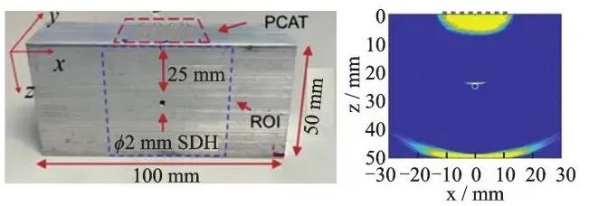 Figure 5 Schematic Diagram of Coated Phased Array Probes and Their Applications
4

Embedded Phased Array Probes
Smart materials with embedded sensors are suitable for long-term, continuous structural health monitoring, and because they do not damage the aerodynamic design of surfaces, they are particularly suitable for aerospace applications. Additionally, due to the protection of smart material composite structures, sensors are less affected by external environments and have higher SNR. Currently, embedded phased array ultrasonic probes are one of the main types of embedded sensors in smart materials.Su et al. used chemical vapor deposition to graft carbon nanotubes (CNT) in situ onto glass fibers (GF) in fiber textiles, preparing 20 embedded CNT-g-GF sensors, and then weaving high-conductivity films into textiles as wires. The schematic diagram of the embedded phased array probe and its application is shown in Figure 6. The results showed that the higher the mass fraction of carbon nanotubes, the greater the wave amplitude excited by the array, with the S0 mode guided wave response peaking around 225 kHz.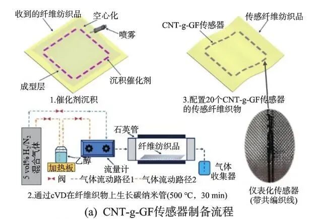
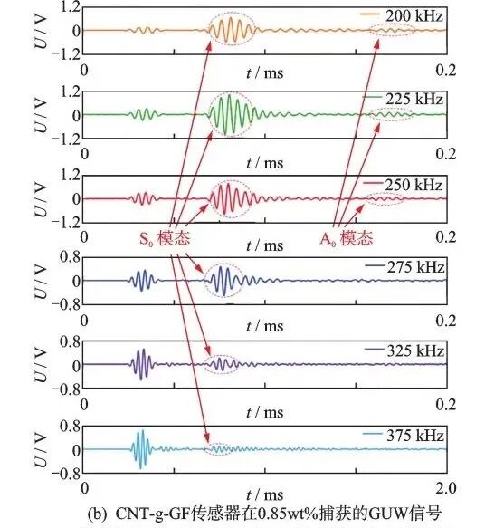 Figure 6 Schematic Diagram of Embedded Phased Array Probes and Their Applications
Opportunities and Challenges
1
Universal Data Formats and Storage Methods for Phased Arrays
Intelligent detection and cloud monitoring of industrial phased arrays are current research hotspots, but due to the lack of uniform data formats and storage methods among various suppliers or research teams, “information islands” are easily formed. To date, there is still a lack of recognized standard datasets in this field, which will limit the development of intelligent detection and cloud monitoring.In the field of ultrasound medicine, the Digital Imaging and Communications in Medicine (DICOM) protocol is the communication and management standard for medical imaging information and related data, which is significant for the development of remote ultrasound technology and intelligent ultrasound-assisted diagnosis and treatment technologies.The Digital Imaging and Communications in Nondestructive Testing (DICONDE) protocol is an extension of the DICOM protocol and is a universal data format that can be used for radiography, CT, eddy current, and ultrasonic testing. Among them, ASTM E2663-23 is the digital ultrasonic testing part of DICONDE, replacing the old standard ASTM E1454—02 (i.e., the current national standard GB/T 25759—2010).
DICONDE inherits the data recycling function of DICOM, supporting the entire process from phased array detection to data preprocessing, database storage, data mining/intelligent discrimination, and re-testing. It is evident that DICONDE helps break down “information islands” and becomes the cornerstone of intelligent decision-making.
2
Hybrid Drive Intelligent Detection/Monitoring Methods for Phased Arrays
Given that the DICONDE protocol is currently unavailable, it is still necessary to achieve intelligent detection of phased arrays with smaller data volumes. Traditional data-driven methods have issues such as insufficient universality and low interpretability, and they are highly dependent on data labeling. Therefore, the key to Artificial Intelligence 2.0 is to organically integrate data-driven and knowledge-driven methods, establishing hybrid-driven methods to improve the interpretability and efficiency of deep learning while reducing data requirements.How to introduce prior knowledge, logical rules, physical laws, and causal relationships to improve generalization ability, interpretability, and robustness is one of the key issues that need to be addressed in the field of intelligent detection of phased arrays.Hybrid-driven methods can be mainly divided into three categories: knowledge-driven, data-driven, and hybrid methods that emphasize both knowledge and data. Physics-informed neural networks (PINN) are a hybrid method that emphasizes knowledge.Alkhadhr et al. used PINN to embed the two-dimensional wave equation as a constraint and trained it with boundary and initial conditions to calculate the transient acoustic field of a three-element phased array probe. After 30,000 iterations, PINN could calculate the acoustic field at different time points. However, when using such methods, the limitations of physical models, data dependence, and computational efficiency must also be considered.
3
Phased Array Measurement Methods for Extreme Service Environments
Currently, there is limited research on phased array ultrasonic testing aimed at extreme environments, especially in the field of nuclear fusion. Nuclear fusion is considered a key to future clean energy, but research on plasma-facing materials (PFM) is a critical bottleneck.PFM must withstand high temperatures, particle radiation, and the effects of neutron transmutation, which impose extremely high requirements on material performance. In China’s fully superconducting Tokamak device “EAST Dongfanghong”, pure tungsten is used as PFM for the cladding and divertor, but it faces issues such as low-temperature brittleness, high ductile-brittle transition temperature, and radiation embrittlement. During fusion reactions, the wall must withstand high-energy neutron bombardment of 14 MeV, with maximum temperatures reaching 1800 °C, easily leading to radiation damage and thermal cracking.Wang et al. used a robotic arm to drive a single probe at 15 MHz for offline water immersion C-scan imaging of the divertor dome, detecting flat-bottom hole defects of φ1.6 mm. Currently, there is still a lack of research on the detection mechanisms of phased arrays for radiation damage and the development of radiation-resistant phased array probes, which will affect the development of defect detection technologies for nuclear fusion reactor materials.
Source Information
Authors: Ji Xuanrong, Deng Qiao, Song Yongfeng, Yuan MaodanAffiliation: Guangdong University of Technology, National Key Laboratory of Precision Electronic Manufacturing Technology and EquipmentSource: Guangdong University Ultrasonic Team, Vibration, Testing and Diagnosis First Author Profile: Ji Xuanrong, Ph.D., Professor, Doctoral Supervisor. Deputy Director of the National Key Laboratory of Precision Electronic Manufacturing Technology and Equipment, Co-founder of the listed company Guangzhou Duopule, Outstanding Industrial Leader Talent in Guangzhou, concurrently serving as Chairman of the Ultrasonic Transducer and Materials Committee of the Ultrasonic Branch of the China Medical Equipment Association, Vice Chairman of the Ultrasonic Committee of the China Non-Destructive Testing Society, and member of the ISO TC135/SC3. His main research directions include new ultrasonic non-destructive testing and monitoring, ultrasonic biological effects, and biomedical imaging. He has presided over major national scientific instrument and equipment development projects, national science and technology support programs, and Pearl River Talent Program innovation teams, and has received awards such as the Science and Technology Achievement Award from the China Instrument and Meter Society and the First Prize of the Science and Technology Award from the China Special Equipment Inspection Association.E-mail: [email protected]