1. Background and Application Value of MBD Technology
In the field of automotive electronics, Model-Based Design (MBD) has become the mainstream method for embedded system development. Compared to traditional handwritten code development, MBD achieves algorithm visualization design through graphical modeling (such as Simulink/Stateflow). Its core advantages include:
– Early design verification: Algorithm logic can be verified during the simulation phase, reducing the risk of real vehicle debugging.
– Automatic code generation: Tools like Embedded Coder generate ISO 26262 compliant code.
– Multi-domain collaboration: Supports co-simulation of control algorithms and physical modeling (such as Simscape).
Currently, a layered architecture has become the industry standard in automotive electronic development:
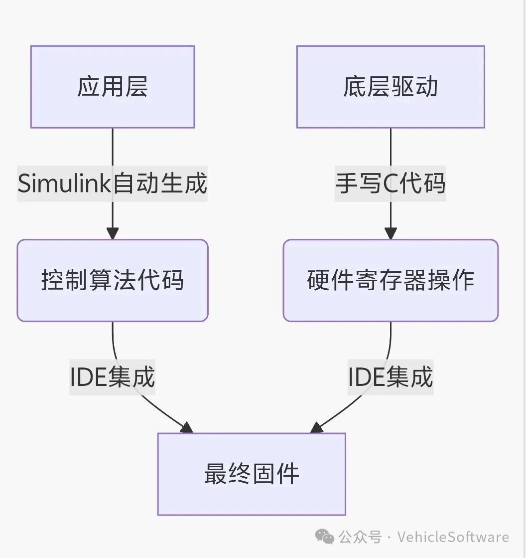
2. Detailed Explanation of Simulink Model Construction
1. Requirement Analysis and Model Architecture
This example implements the core logic for blinking an LED connected to P1.0 at a frequency of 1Hz:
Period T=1s:
First 0.5s → P1.0=1 (LED on)
Last 0.5s → P1.0=0 (LED off)
The corresponding Simulink model needs to include two key modules:
– Pulse Generator: Generates a square wave with a 50% duty cycle.
– Data Type Conversion: Converts boolean values to uint8 for hardware interface.
2. Hardware Interface Mapping
Associate hardware resources through the GPIO Write module:
// Low-level register mapping (implemented in Keil project)
sfr P1 = 0x90; // SFR address of P1 port for 8051
Common mistake avoidance: Ensure to set the port number (Port) of the GPIO Write module to 1 (corresponding to P1), and the pin number (Pin) to 0 (i.e., P1.0).
3. In-depth Configuration of Automatic Code Generation
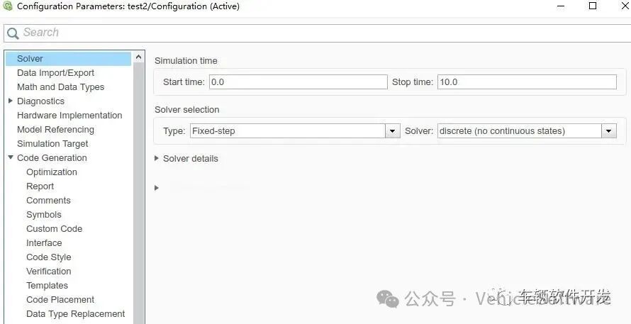
1. Key Considerations for Solver Selection
Embedded systems should choose a fixed-step solver:
– Real-time assurance: Avoid timing jitter caused by variable step sizes.
– Resource optimization: Fixed execution cycles reduce CPU usage.
2. Target System Configuration
Three main reasons for selecting the ert.tlc target file:
1. Generates code that complies with MISRA-C standards.
2. Supports code efficiency optimization (e.g., inline functions).
3. Provides comprehensive code comments for traceability.

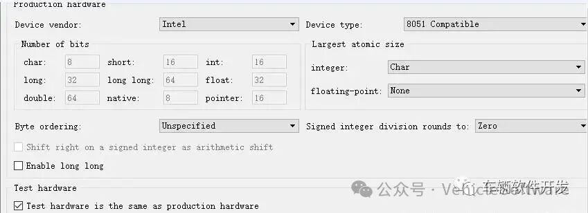
3. Hardware Device Specification
The 8051 Device option directly affects the generated port operation code:
// Example of automatically generated code
void LED_step(void) {
P1 &= 0xFE; // Clear P1.0 bit (generated by Embedded Coder based on hardware configuration)
}
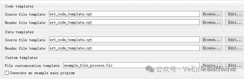
4. Customization of Interface Settings
Uncheck the option to generate the main function example to fit the existing project framework:
– Avoid conflicts with the startup files in the Keil project.
– Retain custom initialization processes.
4. Key Technologies for Keil Project Integration
1. File Organization Structure
Project/
├── App/
│ ├── LED_generated.c // Simulink auto-generated code
│ └── LED.h
├── Driver/
│ ├── GPIO.c // Handwritten low-level driver
│ └── Timer.c
└── main.c // Main scheduling program
2. Example of Handwritten Low-Level Driver
// GPIO.c
void GPIO_Init() {
P1 = 0x00; // Initialize P1 port to low level
P1M0 = 0x01; // Set P1.0 as push-pull output (specific configuration for STC89C52)
}
// main.c
extern void LED_initialize(void);
extern void LED_step(void);
void main() {
GPIO_Init();
LED_initialize(); // Model initialization function
while(1) {
LED_step(); // Model step function
Timer_Delay(1); // 1ms delay
}
}
Reusable design: If the same hardware interface is maintained, subsequent model modifications only require replacing the
“LED_generated.*” files and recompiling.
5. Full Process Verification with Proteus Simulation
1. Circuit Design Specifications
– Microcontroller Model: AT89C52 (compatible with 8051 instruction set)
– LED Connection: P1.0 → 220Ω current limiting resistor → LED anode → GND
2. HEX File Loading Steps
Double-click the microcontroller chip in Proteus:
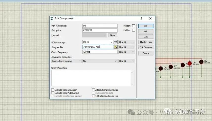
– Select the path of the HEX file generated by Keil.
– Set the clock frequency (default 11.0592MHz).
3. Simulation Verification Indicators
– Timing accuracy: Use an oscilloscope to detect that the P1.0 waveform period should be 1s ±5%.
– Power consumption performance: The current meter detects the LED circuit current to be about 3mA (compliant with safety standards).
Debugging tip: If the LED does not blink, check if the “Digital Animation” in Proteus is enabled.
6. Engineering Experience Expansion
1. Special Requirements for Automotive Electronic Development
– Timing constraints: Adjust task scheduling order through Simulink’s Execution Order.
– Code safety: Enable CRC check function in Embedded Coder (ISO 26262 requirement).
2. Mass Production Optimization Solutions
// Encapsulate low-level drivers as Simulink S-Function (advanced usage)
static void mdlOutputs(SimStruct *S, int_T tid) {
uint8_T *y = ssGetOutputPortSignal(S,0);
P1 = (P1 & 0xFE) | (*y & 0x01); // Only modify P1.0
}
3. Common Problem Troubleshooting Table
Phenomenon Possible Cause Solution
Code compilation error Model header file not included Add inc path in Keil
LED always on/off GPIO initialization configuration error Check P1M0 register configuration
Flashing frequency deviation >10% Timer interrupt not enabled Confirm Timer_Delay.