1. The main clock sources of STM32 are:
-
Internal Clock
-
External Clock
-
Phase Locked Loop (PLL) Frequency Multiplier Output Clock

1.1 Detailed Introduction
HSI (Internal High-Speed Clock)
-
It is an RC oscillator with a frequency of up to 8MHz, which can be used as the system clock and PLL input.
HSE (External High-Speed Clock)
-
The input crystal frequency range is 4-16MHz, which can be used as the system clock and PLL input, and can also be fed into the RTC after 128 division.
LSI (Internal Low-Speed Clock)
-
It is an RC oscillator with a frequency of about 40kHz, supplying the independent watchdog or RTC, and the independent watchdog can only rely on LSI as the clock source.
LSE (External Low-Speed Clock)
-
Usually connects to a 32.768MHz crystal oscillator for the RTC.
PLL (Phase Locked Loop)
-
Used for frequency multiplication output. Since the external crystal oscillator on the development board is only 8MHz, and the maximum operating frequency of STM32 is 72MHz, it can be input through HSI, HSE, or divided by two, and multiplied by PLL (2-16), then input to the system clock.
MCO (Clock Output Pin)
-
Usually corresponds to STM32 PA8, which can select a clock signal output to provide a clock source for external systems.
2. Standard Library Clock Configuration
2.1 STM32 Startup File
First, open startup_stm32f10x_hd.s, which is the startup file for STM32. In this file, you will find a piece of code written in assembly.
      Reset_Handler   PROC
            EXPORT  Reset_Handler    [WEAK]
            IMPORT  __main
            IMPORT  SystemInit
            LDR     R0, =SystemInit
            BLX     R0
            LDR     R0, =__main
            BX      R0
            ENDP
From this assembly code, it can be seen that before executing the main function, the SystemInit function will be executed first.
2.2 Detailed Explanation of SystemInit Function
void SystemInit (void)
{
  /* Reset the RCC clock configuration to the default reset state(for debug purpose) */
  /* Set HSION bit */
  RCC->CR |= (uint32_t)0x00000001;

  /* Reset SW, HPRE, PPRE1, PPRE2, ADCPRE and MCO bits */
#ifndef STM32F10X_CL
  RCC->CFGR &= (uint32_t)0xF8FF0000;
#else
  RCC->CFGR &= (uint32_t)0xF0FF0000;
#endif /* STM32F10X_CL */

  /* Reset HSEON, CSSON and PLLON bits */
  RCC->CR &= (uint32_t)0xFEF6FFFF;

  /* Reset HSEBYP bit */
  RCC->CR &= (uint32_t)0xFFFBFFFF;

  /* Reset PLLSRC, PLLXTPRE, PLLMUL and USBPRE/OTGFSPRE bits */
  RCC->CFGR &= (uint32_t)0xFF80FFFF;

#ifdef STM32F10X_CL
  /* Reset PLL2ON and PLL3ON bits */
  RCC->CR &= (uint32_t)0xEBFFFFFF;

  /* Disable all interrupts and clear pending bits  */
  RCC->CIR = 0x00FF0000;

  /* Reset CFGR2 register */
  RCC->CFGR2 = 0x00000000;
#elif defined (STM32F10X_LD_VL) || defined (STM32F10X_MD_VL) || (defined STM32F10X_HD_VL)
  /* Disable all interrupts and clear pending bits  */
  RCC->CIR = 0x009F0000;

  /* Reset CFGR2 register */
  RCC->CFGR2 = 0x00000000;
#else
  /* Disable all interrupts and clear pending bits  */
  RCC->CIR = 0x009F0000;
#endif /* STM32F10X_CL */

#if defined (STM32F10X_HD) || (defined STM32F10X_XL) || (defined STM32F10X_HD_VL)
  #ifdef DATA_IN_ExtSRAM
    SystemInit_ExtMemCtl();
  #endif /* DATA_IN_ExtSRAM */
#endif

  /* Configure the System clock frequency, HCLK, PCLK2 and PCLK1 prescalers */
  /* Configure the Flash Latency cycles and enable prefetch buffer */
  SetSysClock();

#ifdef VECT_TAB_SRAM
  SCB->VTOR = SRAM_BASE | VECT_TAB_OFFSET; /* Vector Table Relocation in Internal SRAM. */
#else
  SCB->VTOR = FLASH_BASE | VECT_TAB_OFFSET; /* Vector Table Relocation in Internal FLASH. */
#endif
}
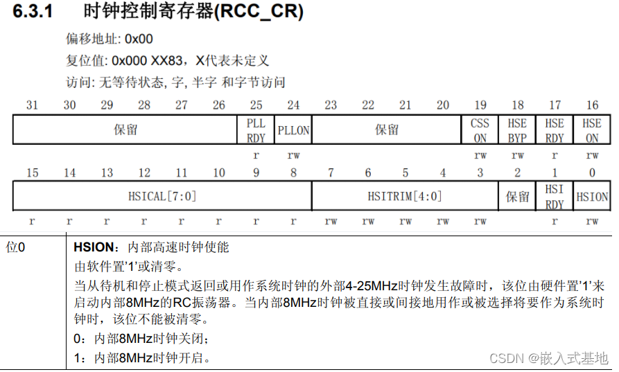
By looking at the register manual, it can be seen that this code is to turn on the internal 8M clock.
Setting the Clock Configuration Register
#ifndef STM32F10X_CL
  RCC->CFGR &= (uint32_t)0xF8FF0000;
#else
  RCC->CFGR &= (uint32_t)0xF0FF0000;
#endif /* STM32F10X_CL */
For the corresponding register description, please refer to the 6.3.2 Clock Configuration Register (RCC_CFGR) section of the STM32 Chinese Reference Manual_V10.
For the subsequent code, interested readers can refer to the STM32 Chinese Reference Manual_V10 to see the specific effects of the code.
2.3 Detailed Explanation of SetSysClock() Function
static void SetSysClock(void)
{
#ifdef SYSCLK_FREQ_HSE
  SetSysClockToHSE();
#elif defined SYSCLK_FREQ_24MHz
  SetSysClockTo24();
#elif defined SYSCLK_FREQ_36MHz
  SetSysClockTo36();
#elif defined SYSCLK_FREQ_48MHz
  SetSysClockTo48();
#elif defined SYSCLK_FREQ_56MHz
  SetSysClockTo56();
#elif defined SYSCLK_FREQ_72MHz
  SetSysClockTo72();
#endif
}
The system_stm32f10x.c file will define corresponding macros based on the chip model.
#if defined (STM32F10X_LD_VL) || (defined STM32F10X_MD_VL) || (defined STM32F10X_HD_VL)
/* #define SYSCLK_FREQ_HSE    HSE_VALUE */
 #define SYSCLK_FREQ_24MHz  24000000
#else
/* #define SYSCLK_FREQ_HSE    HSE_VALUE */
/* #define SYSCLK_FREQ_24MHz  24000000 */
/* #define SYSCLK_FREQ_36MHz  36000000 */
/* #define SYSCLK_FREQ_48MHz  48000000 */
/* #define SYSCLK_FREQ_56MHz  56000000 */
#define SYSCLK_FREQ_72MHz  72000000
#endif
3. Clock Configuration Functions
3.1 Clock Initialization Configuration Function
void SystemInit(void);
SYSCLK(System Clock)=72MHz;
AHB Bus Clock (HCLK=SYSCLK)=72MHz;
APB1 Bus Clock (PCLK1=SYSCLK/2)=36MHz;
APB2 Bus Clock (PCLK1=SYSCLK/1)=72MHz;
PLL Main Clock=72MHz;
3.2 Peripheral Clock Enable Configuration Function
void RCC_AHBPeriphClockCmd(uint32_t RCC_AHBPeriph, FunctionalState NewState);
void RCC_APB2PeriphClockCmd(uint32_t RCC_APB2Periph, FunctionalState NewState);
void RCC_APB1PeriphClockCmd(uint32_t RCC_APB1Periph, FunctionalState NewState);
3.3 Clock Source Enable Functions
void RCC_HSICmd(FunctionalState NewState);
void RCC_LSICmd(FunctionalState NewState);
void RCC_PLLCmd(FunctionalState NewState);
void RCC_RTCCLKCmd(FunctionalState NewState);
3.4 Clock Source and Multiplier Configuration Functions
void RCC_HSEConfig(uint32_t RCC_HSE);
void RCC_SYSCLKConfig(uint32_t RCC_SYSCLKSource);
void RCC_HCLKConfig(uint32_t RCC_SYSCLK);
void RCC_PCLK1Config(uint32_t RCC_HCLK);
void RCC_PCLK2Config(uint32_t RCC_HCLK);
3.5 Peripheral Clock Reset Functions
void RCC_APB2PeriphResetCmd(uint32_t RCC_APB2Periph, FunctionalState NewState);
void RCC_APB1PeriphResetCmd(uint32_t RCC_APB1Periph, FunctionalState NewState);
3.6 Custom System Clock
void RCC_HSE_Config(u32 div,u32 pllm)
{
    RCC_DeInit();
    RCC_HSEConfig(RCC_HSE_ON);
    if(RCC_WaitForHSEStartUp()==SUCCESS)
    {
        RCC_HCLKConfig(RCC_SYSCLK_Div1);
        RCC_PCLK1Config(RCC_HCLK_Div2);
        RCC_PCLK2Config(RCC_HCLK_Div1);
        RCC_PLLConfig(div,pllm);
        RCC_PLLCmd(ENABLE);
    while(RCC_GetFlagStatus(RCC_FLAG_PLLRDY)==RESET)
        RCC_SYSCLKConfig(RCC_SYSCLKSource_PLLCLK)
    while(RCC_GetSCLKSource()!=0x08);

    }
}

END
→Follow us, don’t get lost←