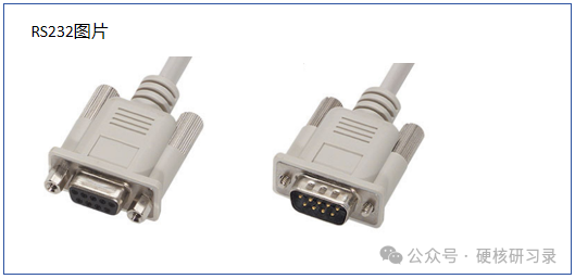
1. RS-232 is a serial communication interface standard, originally established by the Electronic Industries Association (EIA) in the 1960s, aimed at providing a standardized communication interface for computers and their peripheral devices. With the continuous development of computer technology, the RS-232 interface has been widely used and has become one of the most common communication interfaces in early computer systems.
- Communication Method: RS-232 uses a serial communication method, meaning that data is transmitted sequentially bit by bit, allowing for bidirectional data transmission over a single transmission line, which reduces costs and simplifies hardware design.
- Transmission Rate: RS-232 supports various transmission rates, commonly including 9600bps, 19200bps, 38400bps, 57600bps, and 115200bps. Users can select the appropriate transmission rate based on actual application requirements.
- Transmission Distance: Without a modem, the effective transmission distance of RS-232 generally does not exceed 15 meters. This is due to its low signal levels and the use of single-ended transmission, which makes it susceptible to interference.
- Signal Levels: RS-232 uses negative logic levels, specifying that the voltage range for logic “1” is -3V to -15V, and for logic “0” it is +3V to +15V. This voltage standard is not compatible with TTL (Transistor-Transistor Logic) levels, requiring level conversion to connect with TTL circuits.
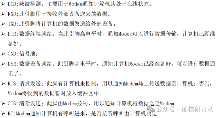
Interface Pin Definitions
 Connection Method 1 (Simple Connection)
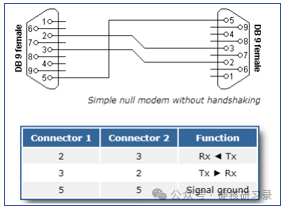 Connection Method 2
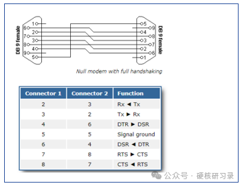 Note: Pin 1 is used by the modem (DCE device) to indicate to the data terminal equipment (DTE) that it has detected a carrier signal from the remote modem, meaning the communication link has been established, and informs the DTE to prepare to receive data. If pin 1 is not connected, the data terminal equipment will not know whether the modem has successfully established a communication link, which may lead to data reception issues and hinder normal communication based on modulation.
However, in some simple application scenarios, if the requirements for detecting the communication link status are not high, or if the establishment of the communication link is confirmed through other means, pin 1 may not be connected, but this may reduce the reliability and stability of the communication.
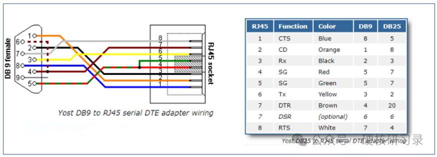
Connection Method 3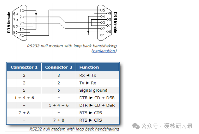
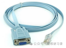
Connection Method 4 (Another end leads out from RJ45 port)
On TxD and RxD: Logic 1 (MARK) = -3V ~ -15V
Logic 0 (SPACE) = +3 ~ +15V
On control lines such as RTS, CTS, DSR, DTR, and DCD:
Signal valid (on, ON state, positive voltage) = +3V ~ +15V
Signal invalid (off, OFF state, negative voltage) = -3V ~ -15V
2. Circuit Design
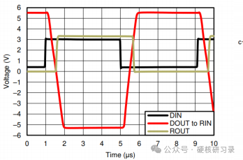
Transmission Timing
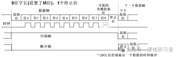
The start is from high to low, and the idle state is high level.
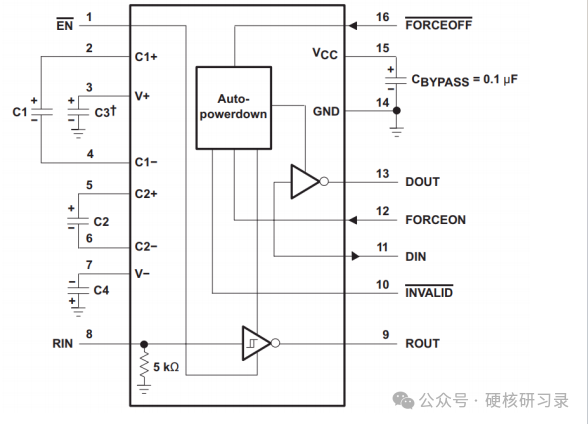
First, let’s look at a commonly used serial port chip, the MAX3221.
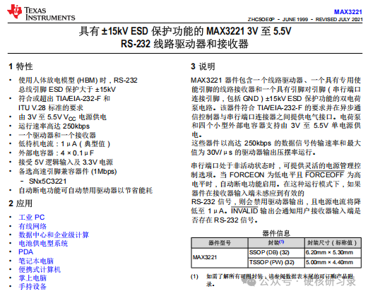
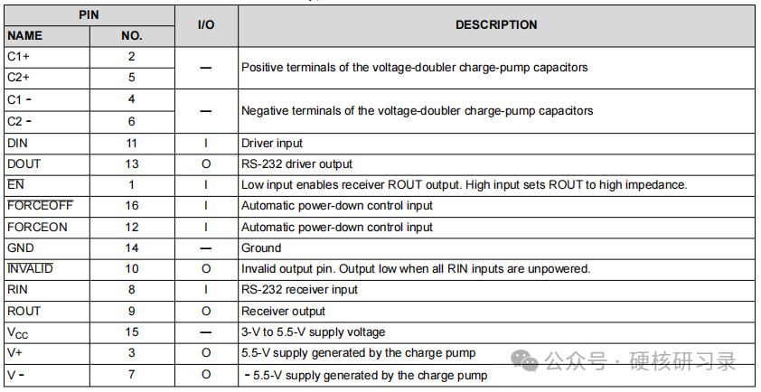
Explanation of several unfamiliar pins:
C1+, C1-, C2+, C2-: The chip has internal piezoelectric charges that need to be released, and external capacitors should be added as required.
Din, Dout, Rin, Rout, EN: These do not need much explanation.
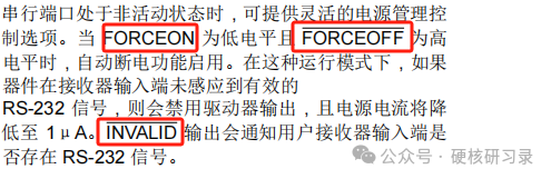
FORCEOFF, FORCEON, invalid: The two are for power management; when there is no data on the 232 line, the power can be turned off to enter standby mode, reducing power consumption.
V+ V-: The TTL level will be converted to a higher voltage of +5.5V and -5.5V after passing through the chip, which has an internal power supply for boosting and bucking.
The solution provided by the chip datasheet:
 Actual application connection:
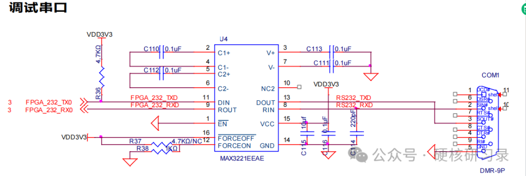 Note: There is a pull-up resistor above FPGA_232_TXD, and it is best to add this pull-up. Some chips have internal pull-ups that can be omitted; the same applies to the receiving input on the other end.