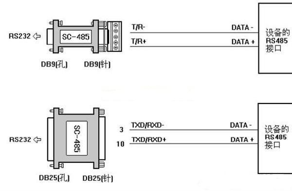
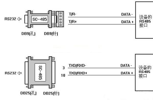
Typically, we use serial ports for direct broadcasting and switching control of video servers, recorders, and switchboards, mainly utilizing RS-232, RS-422, and RS-485 interfaces. Below we will discuss the serial port interface standards, usage, and external plugins and cables.
The RS-232, RS-422, and RS-485 standards only specify the electrical characteristics of the interfaces, without involving connectors, cables, or protocols. Based on this, users can establish their own higher-level communication protocols. For example, video servers come with multiple RS422 serial communication interfaces, each of which can be controlled by an external computer through RS422 communication lines to achieve recording and playback. In addition to providing various control hardware interfaces, video servers also offer protocol interfaces. For instance, the RS422 interface supports not only the RS422 Profile protocol but also protocols controlled via RS422 such as Louth, Odetics, and BVW.
RS-232, RS-422, and RS-485 are all serial data interface standards established and published by the Electronic Industries Alliance (EIA), with RS-232 being released in 1962. RS-422 was developed from RS-232 to improve the shortcomings of RS-232, which has a short communication distance and low speed. RS-422 defines a balanced communication interface, increasing the transmission speed to 10Mbps and extending the transmission distance to 4000 feet (when the speed is below 100Kbps), allowing up to 10 receivers to be connected on a single balanced bus. RS-422 is a unidirectional, balanced transmission specification that allows one transmitter to send data to multiple receivers, named TIA/EIA-422-A standard. To expand its application range, EIA established the RS-485 standard in 1983 based on RS-422, adding multipoint, bidirectional communication capabilities, allowing multiple transmitters to connect on the same bus while enhancing the driving capability of transmitters and conflict protection features, expanding the common mode range, later named TIA/EIA-485-A standard.

1. RS-232 Serial Interface Standard
Currently, RS-232 is the most widely used serial interface in PC and communication industries. RS-232 is defined as a single-ended standard that increases communication distance in low-speed serial communications. RS-232 adopts an unbalanced transmission method, known as single-ended communication. The data signal at the receiving and transmitting ends is relative to the signal ground. Typical RS-232 signals swing between positive and negative levels. When sending data, the transmitter outputs a positive level between +5~+15V and a negative level between -5~-15V. When there is no data transmission, the line is at TTL level, which changes from TTL level to RS-232 level and back to TTL level from the start of data transmission to the end. The receiver’s typical working levels are +3~+12V and -3~-12V. Due to the small difference of only about 2V to 3V between the sending and receiving levels, its common mode rejection capability is poor. Additionally, the distributed capacitance on twisted pairs limits the maximum transmission distance to about 15 meters with a maximum speed of 20Kbps. RS-232 is designed for point-to-point communication (i.e., only one pair of receiving and transmitting devices), with a driver load of 3kΩ~7kΩ. Therefore, RS-232 is suitable for communication between local devices.
2. RS-422 and RS-485 Serial Interface Standards
(1) Balanced Transmission
Unlike RS-232, RS-422 and RS-485 use differential transmission methods, also known as balanced transmission, utilizing a pair of twisted wires, where one wire is defined as A and the other as B. Typically, the positive level between the sending driver A and B is between +2~+6V, representing one logic state, while the negative level is between -2V~6V, representing another logic state. There is also a signal ground C. In RS-485, there is an “enable” terminal, which is optional in RS-422. The “enable” terminal is used to control the connection and disconnection of the sending driver and transmission line. When the “enable” terminal is active, the sending driver is in a high-impedance state, referred to as the “third state,” distinct from logic “1” and “0.”
(2) RS-422 Electrical Specifications
Due to the high input impedance of the receiver and the stronger driving capability of the sending driver compared to RS-232, multiple receiving nodes can be connected on the same transmission line, allowing up to 10 nodes. This means one master device and the rest as slave devices, where slave devices cannot communicate with each other. Thus, RS-422 supports point-to-multipoint bidirectional communication. The RS-422 four-wire interface uses separate sending and receiving channels, so there is no need to control data direction. Any necessary signal exchange between devices can be achieved via software (XON/XOFF handshake) or hardware (a pair of separate twisted wires). The maximum transmission distance of RS-422 is 4000 feet (approximately 1219 meters), with a maximum transmission speed of 10Mbps. The length of the balanced twisted pair is inversely proportional to the transmission speed; the maximum transmission distance can only be achieved at speeds below 100Kbps. The maximum speed transmission can only be obtained at very short distances. Generally, the maximum transmission speed on a 100-meter twisted pair is only 1Mbps. RS-422 requires a termination resistor, with a resistance value approximately equal to the characteristic impedance of the transmission cable. In long-distance transmission, termination resistors may not be necessary, typically not required below 300 meters. The termination resistor is connected at the farthest end of the transmission cable.
(3) RS-485 Electrical Specifications
Since RS-485 is developed from RS-422, many electrical specifications of RS-485 are similar to those of RS-422. Both use balanced transmission methods and require termination resistors on the transmission line. RS-485 can operate in both two-wire and four-wire modes, with the two-wire mode allowing true multipoint bidirectional communication. The RS-485 bus is widely used when communication distances range from several meters to thousands of meters. RS-485 employs balanced sending and differential receiving, thus having the ability to suppress common mode interference. Additionally, the bus transceiver has high sensitivity, capable of detecting voltages as low as 200mV, allowing the transmission signal to be recovered from kilometers away. RS-485 operates in half-duplex mode, meaning only one point can be in sending state at any time; thus, the sending circuit must be controlled by an enable signal. RS-485 is very convenient for multipoint interconnection, which can save many signal lines. Using RS-485 can form a distributed system, allowing up to 32 drivers and 32 receivers to be connected in parallel. The difference between RS-485 and RS-422 also lies in their common mode output voltages; RS-485 ranges from -7V to +12V, while RS-422 ranges from -7V to +7V. RS-485 meets all RS-422 specifications, allowing RS-485 drivers to be used in RS-422 networks. Like RS-422, RS-485 has a maximum transmission distance of approximately 1219 meters and a maximum transmission speed of 10Mbps. The length of the balanced twisted pair is inversely proportional to the transmission speed; the maximum cable length can only be used at speeds below 100Kbps. Only at very short distances can the maximum speed transmission be obtained. Generally, the maximum transmission speed on a 100-meter twisted pair is only 1Mbps.

(4) Installation Considerations for RS-422 and RS-485 Networks
RS-422 can support 10 nodes, while RS-485 supports 32 nodes, thus forming a multi-node network. The network topology generally adopts a terminal-matching bus structure and does not support ring or star networks. When constructing a network, the following points should be noted:
* Use a twisted pair cable as the bus, connecting each node in series. The lead length from the bus to each node should be as short as possible to minimize the impact of reflected signals in the lead on the bus signal.
* Ensure the continuity of the bus characteristic impedance; signal reflections will occur at points of impedance discontinuity. The following situations can easily cause such discontinuity: using different cables for different sections of the bus, having too many transceivers closely installed on one section of the bus, or having excessively long branch lines leading to the bus.
In summary, a single, continuous signal channel should be provided as the bus.


To facilitate better learning for everyone, Changxue Electronics Network has specially added a public account focused on microcontrollers and EDA, pushing relevant knowledge every day, hoping to assist your learning!

