Proteus is a program with a unique capability to simulate the operation of microcontroller circuits. Another excellent feature, similar to other programs, is the design of printed patterns. Sometimes the devices provided by the program are not available.Proteus allows users to create custom components, which is crucial for designs using special devices or new chips. This article details the steps for designing components, and the preparations needed before design include: collecting component datasheets, preparing component symbol diagrams (which can be hand-drawn or referenced from standards), determining component package information, and preparing SPICE models (if simulation is required).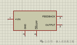 For example, I want to design a printed circuit board using the switch voltage regulator IC LM2576, as shown in the figure.
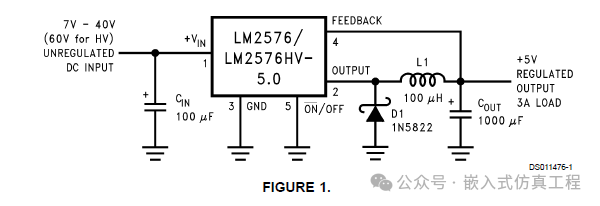
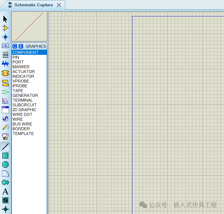
To create the schematic (SCH) for the circuit, use the ISIS circuit drawing program in Proteus (this program is used in the section to draw circuits for simulation). There are two tools available for creating the component:
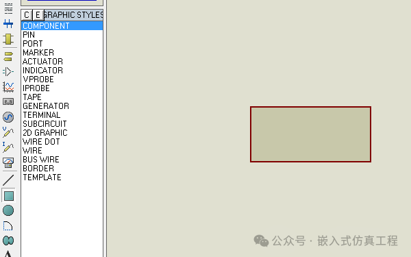
1. Create a component, as shown in the figure.
 2. Design the component pins.
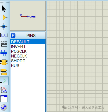 1. Click on Library –> Library Manager menu to create the required library file.
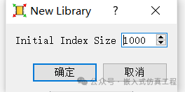
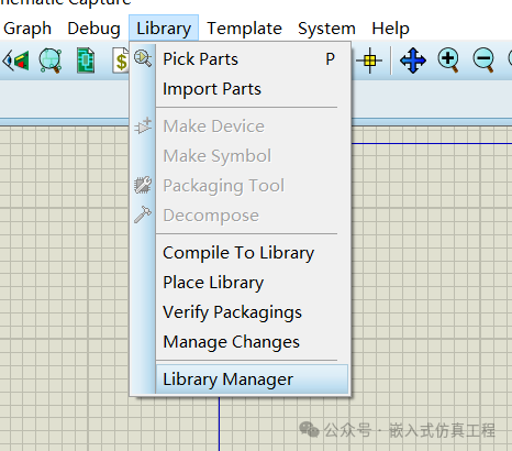
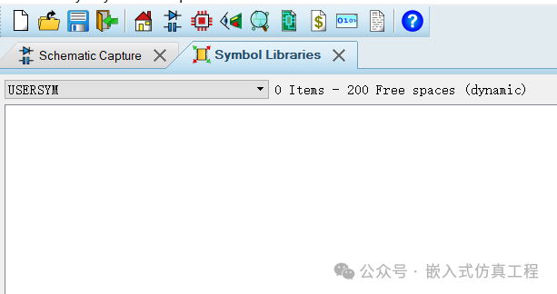
Select the library you want in the opened dialog (in this case, USESYM).
 2. Click to create the library.
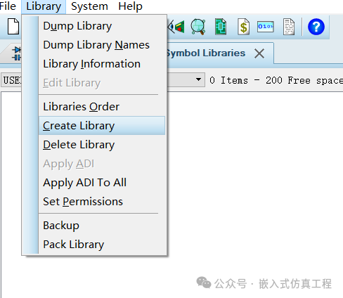
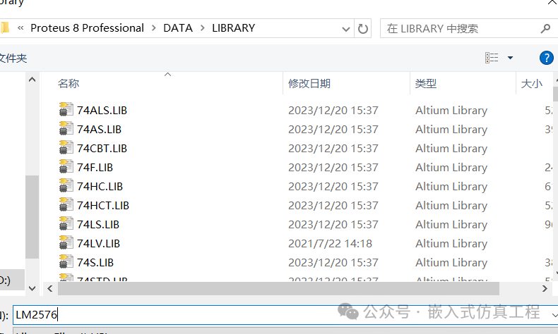
3. Name the required library file. (The name here is LM2576).
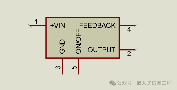
4. Use the drawing tool to draw the component.
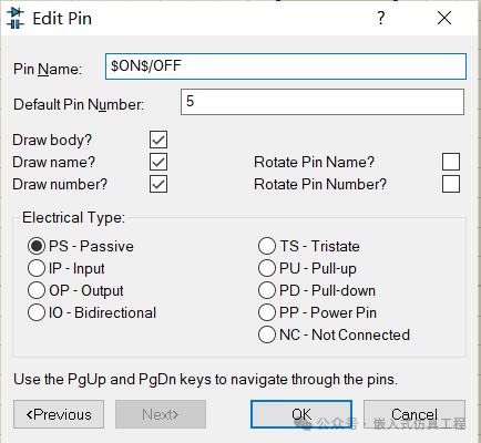
5. Draw the component pins.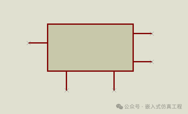 6. Specify the name and number for each pin. This can be done by double-clicking the pin you want to define and entering the desired value, as shown in the figure.
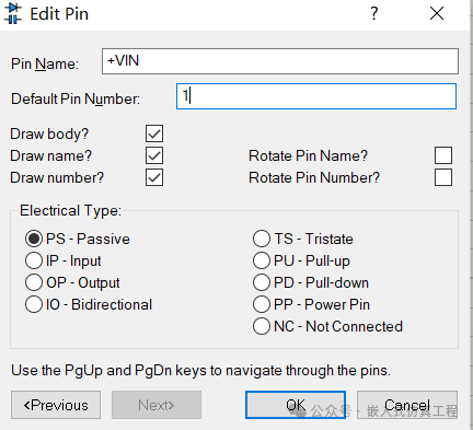
7. If there is a horizontal line above any pin, use $ to close the name before/after. For example, if you want to add a dash above the word ON, enter $ON$.
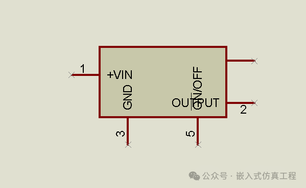
8. Arrange positions appropriately. (To prevent pin overlap).
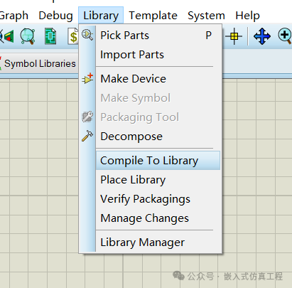
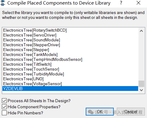
9. Compile the library (select the library name to compile).
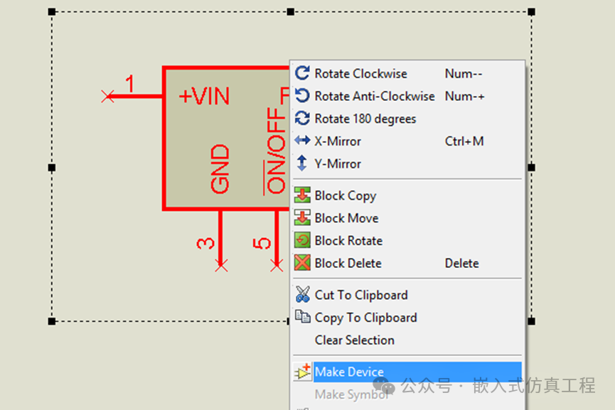
10. Drag the created component into the box and click Make Device.
 11. Enter the device name and device serial number to be displayed.
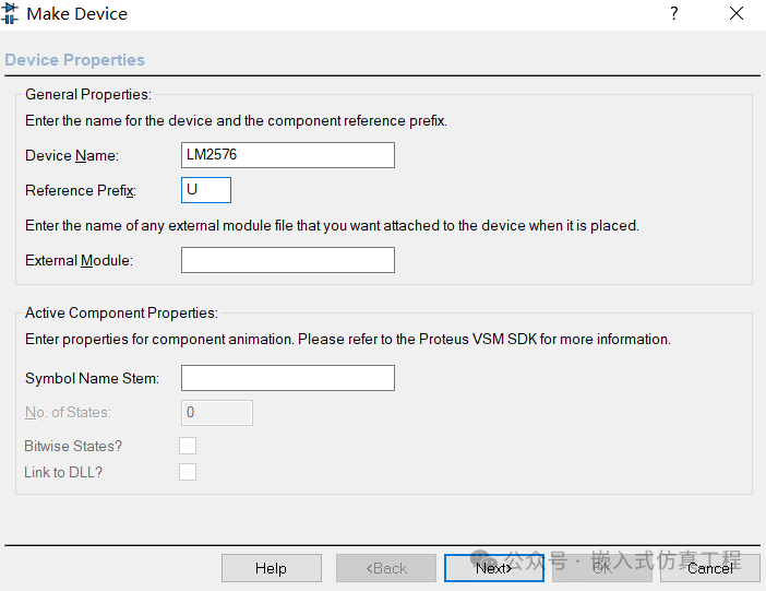 12. If there is no body text, skip this step. (You can create it first and come back to add it.) However, if the program can use other bodies already available in the program, click the add/edit button to select that component.
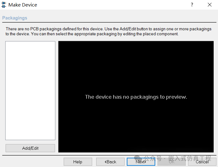 13. If there are no available simulation files… skip this step. (The simulation file is a DLL file used to manage the simulation of the circuit.)
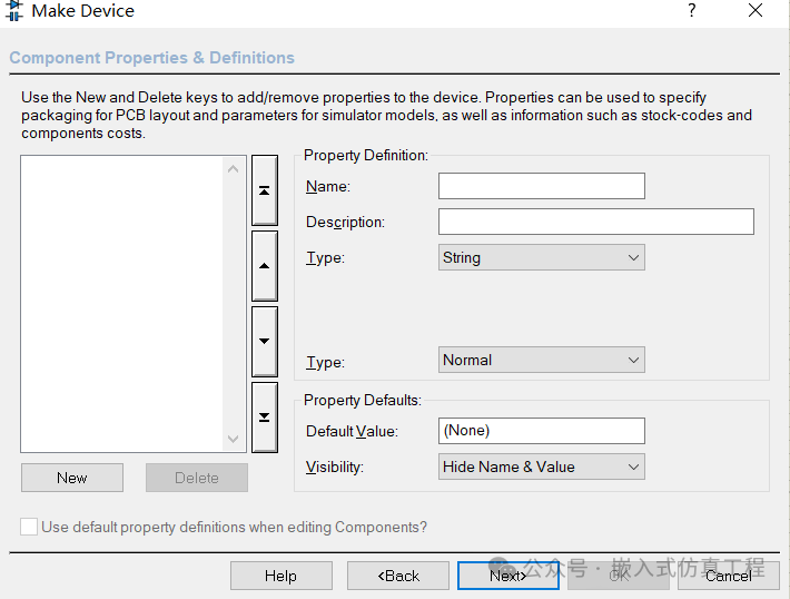 14. Datasheet address, skip if not available.
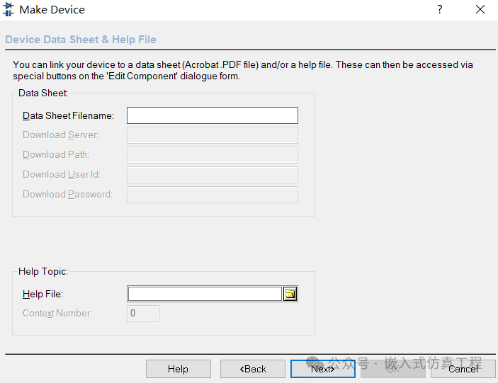 15.Select the library to store the device. Here, select the previously createdPraphaslibrary. In the left pane, select the project where you want the device to be located.
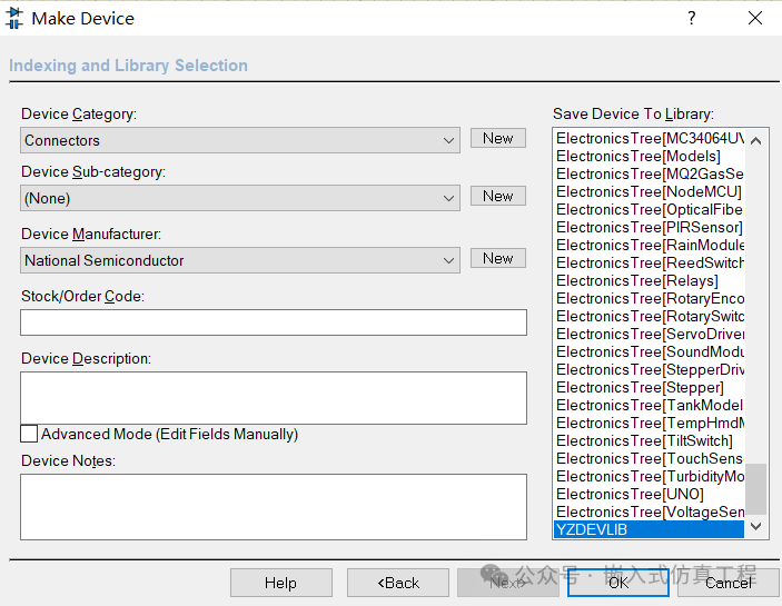 16. When the SCH library creation process is complete, the device name will appear in the left list.
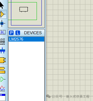 17. When selecting the component to use, the device we created will appear in the list, using the details we specified during the creation process (but without a PCB package yet).
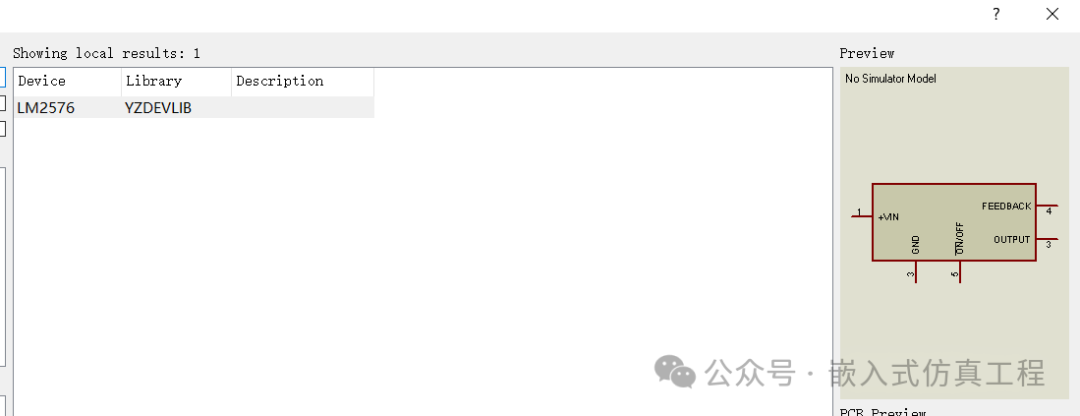 18. When double-clicking the component, there will be no configuration options because the device we created does not have a simulation file. And we did not set any values in step 13.
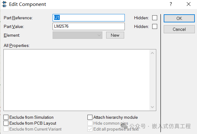 19. The LIBRARY folder will contain the library file we created. (Copy and save for use on other devices).
 By following the above steps, you can create custom components that fully meet design requirements and ensure they work properly in schematic design, simulation, and PCB layout.