Click on the above “Beginner’s Guide to Vision” to select Star or Top.
Important information delivered promptly
With the advancement of imaging technology, the types of cameras and their interfaces continue to evolve to meet the demands of various applications. For machine vision applications in industries such as semiconductor, electronics, biotechnology, assembly, and manufacturing, using the best camera systems to complete the task at hand is crucial for obtaining the best image quality. Understanding camera types, digital interfaces, power supply, and software parameters provides a great opportunity to transition from imaging novices to imaging experts, ranging from analog and digital cameras to interlaced and progressive scan formats, as well as FireWire and GigE interfaces.
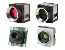
Camera Types and Their Advantages
Analog and Digital Cameras
At the most general level, cameras can be divided into two types: analog and digital. Analog cameras transmit continuously variable electronic signals in real time. The frequency and amplitude of this signal are then interpreted as video information by analog output devices. The quality of the analog video signal and the way it is interpreted both affect the final video image. Moreover, this data transmission method has its pros and cons. Generally, analog cameras are cheaper and simpler than digital cameras, making them an economical and straightforward solution for general video applications. However, the resolution (number of TV lines) and frame rate of analog cameras have their limits. For example, one of the most common video signal formats known in the U.S. as NTSC is limited to about 800 TV lines (typically 525) and 30 frames per second. The PAL standard uses 625 TV lines at a frame rate of 25 frames per second. Analog cameras are also easily affected by electronic noise, depending on factors such as cable length and connector type, which are often overlooked.
Digital cameras, as the latest introduction, have steadily become the most popular type of camera, transmitting binary data (“zeros and ones”) in the form of electronic signals. Although the voltage corresponding to the light intensity of a given pixel is continuous, the analog-to-digital conversion process discretizes it and distributes grayscale values between 0 (black) and 2N-1, where N is the encoding. Output devices then convert the binary data into video information. Importantly, there are two main unique differences between digital and non-analog camera types:
-
The digital video signal is identical when it leaves the camera and when it arrives at the output device.
-
The video signal can only be interpreted in one way.
These differences eliminate errors in signal transmission and interpretation caused by display. Compared to analog cameras, digital cameras typically offer higher resolution, higher frame rates, less noise, and more features. Unfortunately, these advantages are associated with cost – digital cameras are usually more expensive than analog cameras. Additionally, feature-rich cameras may involve more complex setups, even for video systems that only require basic functionality. In most cases, digital cameras are also limited to shorter cable lengths. Table 1 provides a brief comparison of analog and digital camera types.
| Table 1: Comparison of Analog and Digital Camera Types | |
|---|---|
| Analog Cameras | Digital Cameras |
| Vertical resolution is limited by the bandwidth of the analog signal | Vertical resolution is not limited; high resolution can be provided in both horizontal and vertical directions |
| Standard size sensors | No bandwidth limitations, offering a large number of pixels and sensors for high resolution |
| Computers and capture boards can be used for digitization, but are not required for display | Computers and capture boards (in some cases) are needed to display the signal |
| Analog printing and recording easily incorporated into the system | Signals can be compressed, allowing users to transmit in low bandwidth |
| Signals are easily affected by noise and interference, leading to quality loss | Output signals are digital; there is almost no signal loss during signal processing |
| Limited frame rates | High frame rates and shutters |
Interlaced and Progressive Scan Cameras
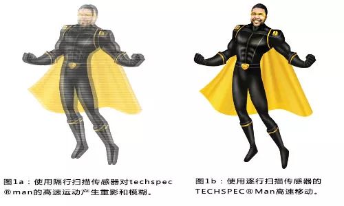
Camera formats can be divided into interlaced, progressive scan, area scan, and line scan. For ease of comparison, it is best to divide them into interlaced vs. progressive and area vs. line scan. Traditional CCD cameras use interlaced scanning on the sensor. The sensor is divided into two fields: odd fields (1st, 3rd, 5th, etc.) and even fields (2nd, 4th, 6th, etc.). These fields are then combined into a single complete frame. For example, at a frame rate of 30 frames per second (fps), each field is read at 1/60 of a second. For most applications, interlaced scanning does not cause issues. However, some problems may arise in high-speed applications because by the time the second field is scanned, the object has already moved. This can lead to ghosting or blurring effects in the image (Figures 1a – 1b). In Figure 1a, notice how the TECHSPEC® Man appears skewed when photographed with an interlaced sensor.
In contrast, progressive scan addresses high-speed issues by sequentially scanning lines (1st, 2nd, 3rd, 4th, etc.). Unfortunately, the output of progressive scan has not yet been standardized, so caution should be exercised when selecting hardware. Some progressive scan cameras provide analog output signals, but few displays can show the image. For this reason, it is recommended to use a capture card to digitize the analog image for display.
Area Scan and Line Scan Cameras
In area scan cameras, the imaging lens focuses on the object to be imaged onto the sensor array and samples the image at the pixel level for reconstruction (Figure 2). This is convenient if the image is not moving quickly or the object is not very large. A familiar digital snapshot camera is an example of an area scan device. With line scan cameras, pixels are arranged in a linear fashion, making the array very long (Figure 2). The long array is ideal because the amount of information read out per exposure is significantly reduced, and the readout speed increases due to the absence of column shift registers or multiplexers; in other words, as the object moves past the camera, the image is captured line by line and reconstructed with software.
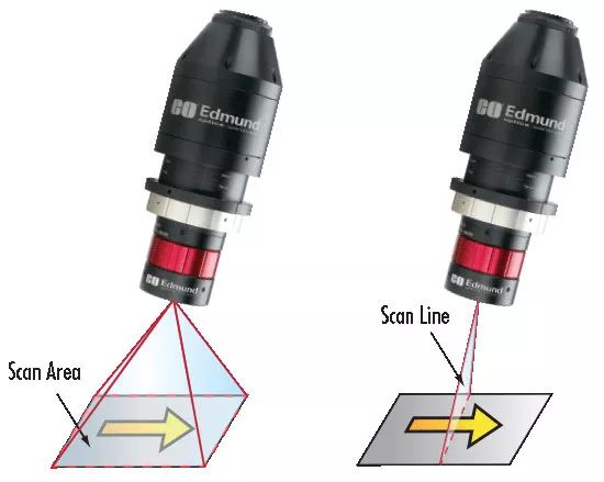
Figure 2: Schematic Diagram of Area Scan Technology (Left) and Line Scan Technology (Right)
| Table 2: Comparison of Area Scan and Line Scan Cameras | |
|---|---|
| Area Scan Cameras | Line Scan Cameras |
| 4:3 (H:V) aspect ratio (typical) | Linear sensor |
| Large sensors | Larger sensors |
| High-speed applications | High-speed applications |
| Fast shutter times | Builds image one line at a time |
| Lower cost than line scan | Object passes underneath the sensor |
| Wider range of applications than linear scanning | Ideal for capturing wide objects |
| Simple installation | Special alignment and timing requirements; complex integration but simple lighting |
Time Delay and Integration (TDI) vs. Traditional Line Scan Cameras
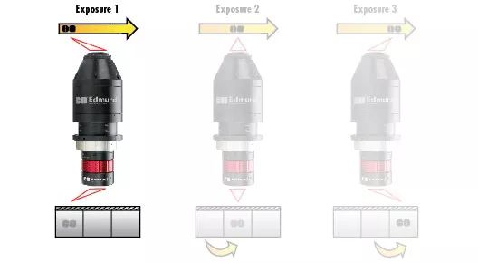
In traditional line scan cameras, the object moves past the sensor, and the image is scanned line by line. Due to the short exposure time for each line reconstructed from the linear array, very little light is collected. Therefore, this requires a lot of lighting (think of a copier or document scanner). An alternative method is the Time Delay and Integration (TDI) line scan camera. In these arrangements, multiple linear arrays are placed side by side. After the first array is exposed, the charge is transferred to the adjacent line. As the object moves across the line spacing, a second exposure is made over the first object, and so on. Thus, each line of the object is repeatedly imaged, and the exposures are summed together (Figures 3a-3b). This reduces noise, thereby increasing the signal. Moreover, it demonstrates the concept of triggering, where the exposure of the pixel array is synchronized with the motion of the object and the flash of illumination.
Digital Camera Interfaces
Due to transmission noise, distortion, or other signal degradation not affecting the information being transmitted, digital cameras have become popular over the past decade. Since the output signal is digital, there is almost no information loss during transmission. As more users turn to digital cameras, imaging technology has also entered numerous digital interfaces. The imaging landscape will look significantly different in another decade, but the most common interfaces today are capture cards, GigE, and USB (Table 3).
As with many camera selection standards, there is no single best interface choice; rather, the most suitable device must be chosen for the application at hand. Asynchronous or deterministic transmission allows for data transmission receipts, ensuring signal integrity, with timeouts due to bidirectional communication. In isochronous transmission, scheduled packet transfers occur (e.g., every 125μs), ensuring timing, but allowing for the possibility of dropping packets at high transmission rates.
Capture Cards
Image processing typically involves using a computer. Capture cards allow users to input the output from analog camera signals into the computer for analysis; or analog signals (NTSC, YC, PAL, CCIR), capture boards contain an analog-to-digital converter (ADC) for digitizing signals for image processing. Others can view the signal in real-time. Users can then capture images and save them for future operation and printing. Capture boards include basic capture software that allows users to save, open, and view images. The term capture board also refers to PCI cards, which are necessary for obtaining and interpreting data from digital camera interfaces, but not based on standard computer connectors.
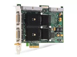
FireWire (IEEE 1394 / IIDC DCAM Standard)
Due to the widespread use of FireWire ports on computers, FireWire (also known as IEEE 1394) is a popular serial isochronous camera interface. Although FireWire.a is one of the slower interfaces in terms of transmission rate, both FireWire.a and FireWire.b allow for the connection of multiple cameras and provide power through FireWire cables. Hot swapping/hot plugging is not recommended as the design of the connector can cause power pins to short circuit, potentially damaging the port or device.
CameraLink®
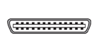
CameraLink® is a high-speed serial interface standard specifically developed for machine vision applications, most notably involving automated inspection and process control.
Capture cards are required, and the camera must be powered separately. Because special wiring is required in addition to low-voltage differential pair (LVDP) signal lines, a separate asynchronous serial communication channel is needed to maintain the full bandwidth of data transmission. A single cable base configuration allows for a dedicated video transmission of 255 MB/s. Dual output (full configuration) allows separate camera parameters to be sent/received lines, freeing up more data transmission space (680 MB/s) for extreme high-speed applications.
CameraLink®HS (High Speed) is an extension of the CameraLink® interface, achieving higher speeds (up to 2100MB/s for 15 meters) by using more cables. Additionally, CameraLink®HS can also support fiber optic cables up to about 300 meters long.
GigE (GigE Vision Standard)
GigE is based on the Gigabit Ethernet Internet protocol, using standard Cat-5 and Cat-6 cables as high-speed camera interfaces. Standard Ethernet hardware such as switches, hubs, and repeaters can be used for multiple cameras, but overall bandwidth must be considered whenever using non-peer (direct camera to card) connections. In GigE Vision, the camera control registers are based on the EMVA GenICam standard. Link aggregation (LAG, IEEE 802.3ad) optionally allows some cameras to use multiple Ethernet ports in parallel to increase data transmission rates, and multicast distributes processor load. With support from certain cameras, the network precision time protocol (PTP) can be used to synchronize the clocks of multiple cameras connected to the same network, establishing a fixed delay relationship between relevant exposures. Devices are hot-swappable.
USB (Universal Serial Bus)
Due to the ubiquity of USB 2.0 in computers, it is a popular interface. The speed is not high, but it is convenient; the maximum speed depends on the number of USB peripheral components, as the total bus transmission rate is fixed at 480Mb/s. Cables can be purchased at any computer store. In some cases, such as with laptops, it may be necessary to power the camera separately.
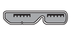
USB 3.0 retains the plug-and-play advantages of USB 2.0 while allowing for higher data transmission rates.
CoaXPress is a single-wire high-bandwidth serial interface that achieves transmission rates of up to 6.25Gb/s, with cable lengths of up to 100m. Multiple cables can be used for speeds up to 25Gb/s. Like PoE, coaxial cables are also an available option.
CoaXPress image capture cards are required.
| Table 3: Comparison of Common Digital Camera Interfaces | |||||
|---|---|---|---|---|---|
| Digital Signal Options | FireWire 1394.b | CameraLink® | USB 2.0 | USB 3.0 | Gigabit Ethernet |
| Image | 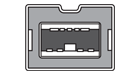 |
 |
 |
 |
 |
| Data Transmission Rate: | 800 Mb/s | 3.6 Gb/s (full configuration) | 480 Mb/s | 5Gb/s | 1000 Mb/s |
| Devices: | Up to 63 | 1 | Up to 127 | Up to 127 | Unlimited |
| Capture Board: | Optional | Required | Optional | Optional | Not required |
| Power: | Optional | Required | Optional | Optional | Required (PoE optional) |
Powering the Camera
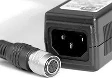
Many camera interfaces allow for remote powering of the camera through the signal cable. If this is not the case, power is typically supplied through a Hirose connector (which also allows for trigger wiring and I/O) or standard AC/DC adapter types. Even in cases where the camera can be powered through the card or port, using an optional power connection is beneficial. For example, daisy-chained FireWire cameras or systems running from a laptop are ideal cases for additional power. Furthermore, cameras with large high-speed sensors and onboard FPGAs require more power than can be supplied through the signal cable.
Power over Ethernet (PoE)
Currently available power injectors allow specific cameras to be powered through GigE cables. This is important when space constraints do not allow the camera to have its own power supply, such as in factory floor installations or outdoor applications. In this case, the injector adds standard power along the cable line somewhere, transmitting to the camera and computer. However, not all GigE cameras are PoE compatible. As with other interfaces, if peak performance is required, power should be supplied separately from the signal cable. In PoE, the power voltage is based on a higher standard voltage than what standard cameras can provide; this requires more electronic components and results in greater power consumption, necessitating complex heat dissipation designs to avoid increased thermal noise, which can degrade image quality.
Analog CCD Output Signals
Analog video signals come in several different formats. The format defines the frame rate, number of display lines, time dedicated to display and blanking, synchronization, bandwidth, and signal details. In the U.S., the Electronic Industries Alliance (EIA) defines monochrome signals as RS-170. The color version is defined as RS-170A, commonly referred to as the National Television System Committee (NTSC). Both RS-170 and NTSC are composite signals. This means that all color and intensity information is combined into one signal. There are some component signals (YC and RGB) that separate chrominance (color) from luminance (color intensity). CCIR is the monochrome standard in Europe, while PAL and SECAM are the color standards in Europe. Note: The camera and display formats must be the same for proper imaging.
Laptops and Cameras
Although many digital camera interfaces are available for laptops, it is strongly recommended to avoid using standard laptops for high-quality and/or high-speed imaging applications. Typically, the data bus on laptops cannot support full transmission speeds, and resources cannot be fully utilized for high-performance cameras and software. In particular, the performance of standard Ethernet cards in most laptops is far below that of PCIe cards available for desktop computers.
Camera Software
Generally speaking, there are two options for imaging software: camera-specific software development kits (SDKs) or third-party software.
SDKs contain application programming interfaces and code libraries for developing user-defined programs, as well as simple image viewing and acquisition programs that require no coding and provide basic functionality. Using third-party software, camera standards (GenICam, DCAM, GigE Vision) are crucial to ensuring functionality. Third-party software includes NI LabVIEW™, MATLAB®, OpenCV, and more. Typically, third-party software can run multiple cameras and support multiple interfaces, but ultimately it is up to the user to ensure functionality.
Despite the numerous types of cameras, interfaces, power requirements, and software available for imaging applications, understanding the pros and cons of each application allows users to select the best combination for any application. Whether the application requires high data transmission, long cable lengths, and/or daisy chaining, the camera combinations can achieve optimal results.
Good news!
The Beginner's Guide to Vision knowledge planet
is now open to the public👇👇👇


Download 1: OpenCV-Contrib Extension Module Chinese Version Tutorial
Reply "Extension Module Chinese Tutorial" in the "Beginner's Guide to Vision" public account background to download the first Chinese version of the OpenCV extension module tutorial on the internet, covering installation of extension modules, SFM algorithms, stereo vision, target tracking, biological vision, super-resolution processing, and more than twenty chapters of content.

Download 2: Python Vision Practical Project 52 Lectures
Reply "Python Vision Practical Project" in the "Beginner's Guide to Vision" public account background to download 31 practical vision projects including image segmentation, mask detection, lane line detection, vehicle counting, eyeliner addition, license plate recognition, character recognition, emotion detection, text content extraction, and facial recognition, helping to quickly learn computer vision.

Download 3: OpenCV Practical Project 20 Lectures
Reply "OpenCV Practical Project 20 Lectures" in the "Beginner's Guide to Vision" public account background to download 20 practical projects based on OpenCV to achieve advanced learning of OpenCV.

Group Chat

Welcome to join the public account reader group to communicate with peers; currently, there are WeChat groups for SLAM, 3D vision, sensors, autonomous driving, computational photography, detection, segmentation, recognition, medical imaging, GAN, algorithm competitions, etc. (will be gradually subdivided in the future). Please scan the WeChat number below to join the group, and note: "Nickname + School/Company + Research Direction", for example: "Zhang San + Shanghai Jiao Tong University + Vision SLAM". Please follow the format for notes; otherwise, you will not be approved. After successful addition, you will be invited to relevant WeChat groups based on research direction. Please do not send advertisements in the group; otherwise, you will be removed from the group. Thank you for your understanding.~