Abstract
This article provides a detailed introduction to a design scheme for a fully automatic washing machine control simulation system based on the AT89C51 microcontroller. The system implements the core functions of the washing machine through hardware circuit design and software programming, including water level detection, motor control, and washing process management modules. The article includes complete Proteus simulation circuit diagrams, C language source code with detailed comments, and analyzes key technical points in the system design. This design features low cost, high reliability, and ease of expansion, making it a reference case for embedded system learning and home appliance control development.
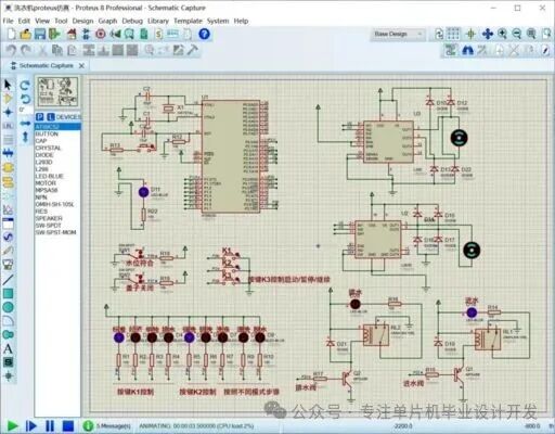
Proteus software’s schematic diagram of the fully automatic washing machine control circuit, including core components such as the microcontroller, buttons, and indicator lights.
1. Overall System Design
1.1 Hardware Architecture
The system uses the AT89C51 microcontroller as the core controller, and the hardware structure mainly includes the following modules (development of a fully automatic washing machine control system using the 51 microcontroller):
- Main Control Module: AT89C51 microcontroller, responsible for processing sensor signals, executing control algorithms, and driving actuators.
- Input Module: Includes a button matrix (for mode selection) and a water level sensor (for analog water level detection).
- Output Module: Relay group (controls the water inlet valve/drain valve), motor drive circuit (H-bridge circuit for forward and reverse rotation).
- Display Module: LED indicator lights (show working status), digital tube (displays remaining time).
- Power Module: Provides a stable +5V voltage using a 7805 voltage regulator chip.
-
The system block diagram is as follows:
-
[Button Input] → [51 Microcontroller] → [Relay Control] ↑ ↓ [Water Level Detection] ← → [Motor Drive] ↓ ↑ [Power Circuit] → [Display Module] -
1.2 Working Process
-
The washing machine control logic follows a typical fully automatic washing process (design of a fully automatic washing machine system based on the 51 microcontroller – Proteus schematic, program):
- Water Inlet Stage: Open the water inlet valve until the preset water level is reached.
- Washing Stage: Motor rotates forward → pause → reverse rotation cycle.
- Drainage Stage: Open the drainage valve to discharge wastewater.
- Spin Stage: Motor rotates at high speed in one direction.
- Completion Alarm: Buzzer indicates that washing is complete.
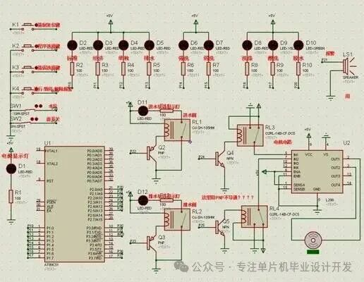
Schematic diagram of the washing machine control circuit based on the 51 microcontroller, showing the connection methods of key components such as relays and diodes.
2. Hardware Circuit Design
2.1 Minimum System of the Microcontroller
Using a typical 51 microcontroller minimum system design:
// Crystal oscillator circuit: 12MHz crystal, 30pF load capacitor// Reset circuit: 10kΩ resistor, 10μF electrolytic capacitor// EA pin connected to high level, using internal program memory
2.2 Motor Drive Circuit
Using the L298N driver chip to construct the H-bridge circuit (51, washing machine control system based on the 51 microcontroller):
sbit MOTOR_A = P2^0; // Motor control line A
sbit MOTOR_B = P2^1; // Motor control line B
void Motor_Ctrl(uint8_t dir){
switch(dir){
case 0: // Stop
MOTOR_A = 0; MOTOR_B = 0; break;
case 1: // Forward
MOTOR_A = 1; MOTOR_B = 0; break;
case 2: // Reverse
MOTOR_A = 0; MOTOR_B = 1; break;
}}
2.3 Water Level Detection Circuit
Using a switch to simulate the water level sensor, which can be replaced by a pressure sensor in practical applications:
sbit WATER_LOW = P1^4; // Low water level detection
sbit WATER_MID = P1^5; // Medium water level detection
sbit WATER_HIGH = P1^6; // High water level detection
uint8_t Check_Water_Level(){
if(WATER_HIGH == 0) return 3;
else if(WATER_MID == 0) return 2;
else if(WATER_LOW == 0) return 1;
else return 0;
}
3. Software Design Implementation
3.1 Main Program Framework
The system adopts a state machine design pattern, with the main loop structure as follows (simple washing machine control system design implemented on the 51 microcontroller):
void main(){
System_Init(); // System initialization
while(1){
switch(Work_State){
case IDLE: Idle_Process(); break;
case WATER_IN: Water_In_Process(); break;
case WASH: Wash_Process(); break;
case WATER_OUT: Water_Out_Process(); break;
case SPIN: Spin_Process(); break;
case ALARM: Alarm_Process(); break;
}
Key_Scan(); // Key scanning
Display(); // Status display
}
}
3.2 Washing Control Algorithm
Implementing a typical washing mode with alternating motor forward and reverse operation:
void Wash_Process(){
static uint8_t step = 0;
static uint16_t timer = 0;
if(++timer >= TIME_WASH){
Work_State = WATER_OUT;
return;
}
switch(step){
case 0: // Forward for 5 seconds
Motor_Ctrl(1);
if(++sub_timer >= 5) { step=1; sub_timer=0; }
break;
case 1: // Pause for 2 seconds
Motor_Ctrl(0);
if(++sub_timer >= 2) { step=2; sub_timer=0; }
break;
case 2: // Reverse for 5 seconds
Motor_Ctrl(2);
if(++sub_timer >= 5) { step=3; sub_timer=0; }
break;
case 3: // Pause for 2 seconds
Motor_Ctrl(0);
if(++sub_timer >= 2) { step=0; sub_timer=0; }
break;
}}
3.3 Timer Interrupt Service
Using Timer 0 to achieve a 1-second reference timing:
void Timer0_ISR() interrupt 1{
static uint16_t count = 0;
TH0 = 0x3C; // 50ms timer initial value
TL0 = 0xB0;
if(++count >= 20){ // 1 second reached
count = 0;
Sys_Tick++; // System clock++
}}
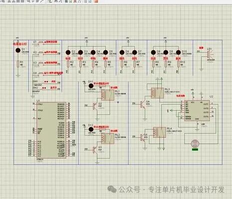
PCB design diagram of the washing machine control system, showing component layout and circuit connections.
4. System Optimization and Expansion
4.1 Function Expansion Suggestions
- Add Temperature Control: Add a DS18B20 sensor to implement warm water washing.
- IoT Access: Implement remote control via the ESP8266 module.
- Energy Consumption Monitoring: Use the HLW8032 chip to achieve water and electricity consumption statistics.
- Fuzzy Control: Automatically adjust water level and time based on the weight of the clothes.
4.2 Anti-Interference Measures
- Connect a flyback diode in parallel with the relay coil.
- Isolate the motor power supply from the logic power supply.
- Use shielded wires for signal lines and keep them away from power lines.
- Implement software filtering algorithms to eliminate key bounce.
- 5. Complete Source Code
- /************************************************* * File Name: Washing_Machine.c * Function: Fully automatic washing machine controller based on AT89C51 * Author: Embedded Tech * Date: 2025-09-11 *************************************************/#include <reg51.h>// Hardware pin definitions#define uint unsigned int#define uchar unsigned char// Motor control pins
sbit MOTOR_A = P2^0;
sbit MOTOR_B = P2^1;// Valve control
sbit VALVE_IN = P2^2; // Water inlet valve
sbit VALVE_OUT = P2^3; // Drain valve// Water level detection
sbit WATER_LOW = P1^4;
sbit WATER_MID = P1^5;
sbit WATER_HIGH = P1^6;// Status indicator lights
sbit LED_WASH = P3^0;
sbit LED_RINSE = P3^1;
sbit LED_SPIN = P3^2;
sbit LED_ALARM = P3^3;// Global variables
uint Sys_Tick = 0; // System clock (seconds)
uchar Work_State = 0; // Working state// State definitions#define IDLE 0#define WATER_IN 1#define WASH 2#define WATER_OUT 3#define SPIN 4#define ALARM 5// Function declarations
void System_Init(void);
void Timer0_Init(void);
void Motor_Ctrl(uchar dir);
uchar Check_Water_Level(void);
void Water_In_Process(void);
void Wash_Process(void);
void Spin_Process(void);
/************************************************* * Main Function *************************************************/
void main(){
System_Init();
Timer0_Init();
while(1){
switch(Work_State){
case IDLE: break;
case WATER_IN: Water_In_Process(); break;
case WASH: Wash_Process(); break;
case WATER_OUT: VALVE_OUT = 1; // Open drain valve if(Check_Water_Level() == 0) Work_State = SPIN; break;
case SPIN: Spin_Process(); break;
case ALARM: LED_ALARM = ~LED_ALARM; // Alarm blinking break;
}
}
}/************************************************* * System Initialization *************************************************/
void System_Init(){
// Initialize IO ports
MOTOR_A = MOTOR_B = 0;
VALVE_IN = VALVE_OUT = 0;// Initialize state
Work_State = WATER_IN;
LED_WASH = LED_RINSE = LED_SPIN = LED_ALARM = 0;EA = 1; // Enable global interrupt
}/************************************************* * Timer 0 Initialization *************************************************/
void Timer0_Init(){
TMOD = 0x01; // Timer 0 mode 1
TH0 = 0x3C; // 50ms timer initial value
TL0 = 0xB0;
ET0 = 1; // Enable Timer 0 interrupt
TR0 = 1; // Start Timer 0
}// Other function implementations…
Conclusion
The fully automatic washing machine control system designed in this article, through hardware circuit design and software programming, achieves the basic automation functions of the washing machine. The system has the following characteristics:
- Low Cost: Utilizes a general-purpose 51 microcontroller with simple peripheral circuits.
- High Reliability: State machine design ensures controllable processes, with comprehensive anti-interference measures.
- Easy to Expand: Modular design facilitates functional expansion and performance enhancement.
- Educational Value: Fully demonstrates the entire process of embedded system development.
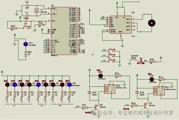 Component layout and interface design of the fully automatic washing machine control system, including the microcontroller, relays, and other key components.