Click the above “Positive Motion Assistant”, stay tuned for new updates!
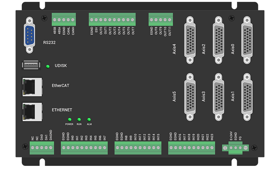
ZMC406 supports 6-axis motion control and can be expanded to a maximum of 32 axes, supporting functions such as linear interpolation, arbitrary arc interpolation, spatial arc, spiral interpolation, electronic cam, electronic gear, and synchronized following.
ZMC406 supports three programming methods: PLC, Basic, and HMI configuration. PC host API programming supports interfaces such as C#, C++, LabVIEW, Matlab, Qt, Linux, VB.Net, and Python.
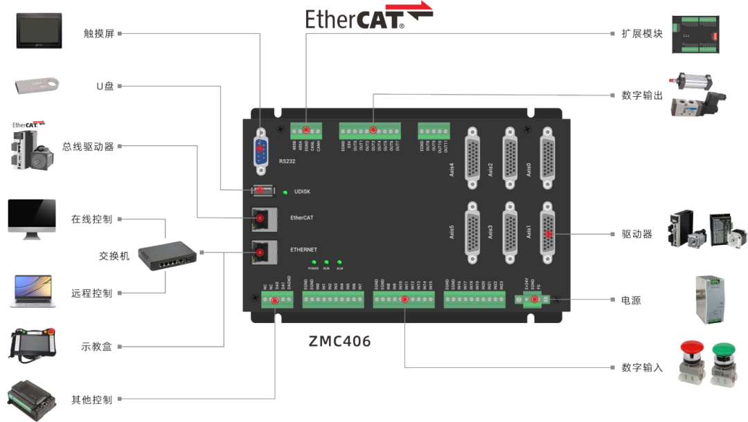
ZMC406 supports 6-axis motion control and can use pulse axes (with encoder feedback) or EtherCAT bus axes. The general I/O includes 24 input ports and 12 output ports, with two analog AD/DA channels each, and the EtherCAT refresh cycle can be as fast as 125us.
-
This type of motion controller has the following advantages compared to PCI motion control cards:
▶▶▶
Concepts Related to Robots
1. Joint Axes and Virtual Axes
2. Forward Kinematics and Inverse Kinematics
▶▶▶
Robot Operation Steps
1. Confirm whether the motor direction is correct.
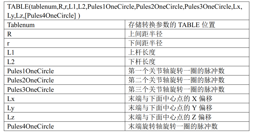

‘From TableNum number, sequentially store the robot structural parameters: upper spacing radius, lower spacing radius, upper arm length, lower arm length, the number of pulses for the first joint axis to rotate one circle, the number of pulses for the second joint axis to rotate one circle, the number of pulses for the third joint axis to rotate one circle, X offset from the end to the center point below, Y offset from the end to the center point below, Z offset from the end to the center point below, the number of pulses for the fourth joint axis to rotate one circle into the Table. TABLE(TableNum,Top_R,Under_R,Top_L,Under_L,OneCirPules_J1,OneCirPules_J2,OneCirPules_J3,Offset_X,Offset_Y,Offset_Z,OneCirPules_J4)3. Set the joint axis parameters and virtual axis parameters.
Each axis’s axis type and pulse equivalent (units) must be set correctly, set to the number of pulses required for the motor to move 1°. The virtual axis’s units are unrelated to the actual number of pulses sent, and are used to set the motion accuracy. The pulse number for 1mm of the virtual axis is generally recommended to be set to 1000, indicating an accuracy of three decimal places.
'Set joint axis type to pulse axis type 1 BASE(Axis_JList(0),Axis_JList(1),Axis_JList(2),Axis_JList(3))' If it is a bus axis type, it can be set to 65 ATYPE = 1,1,1,1 UNITS = UnitsJList(0),UnitsJList(1),UnitsJList(2),UnitsJList(3)' Set joint axis speed, acceleration (generally set to 10 times the speed), and deceleration (generally set to 10 times the speed) SPEED = SpeedJList(0),SpeedJList(1),SpeedJList(2),SpeedJList(3) ACCEL = ADSpeedJList(0),ADSpeedJList(1),ADSpeedJList(2),ADSpeedJList(3)DECEL = ADSpeedJList(0),ADSpeedJList(1),ADSpeedJList(2),ADSpeedJList(3)' S-curve SRAMP = SrampJ(0),SrampJ(1),SrampJ(2),SrampJ(3)' Set virtual axis BASE(Axis_VList(0),Axis_VList(1),Axis_VList(2))' Set virtual axis type to 0 ATYPE = 0,0,0' Set virtual axis pulse equivalent to 1000 -- indicating an accuracy of three decimal places UNITS = 1000,1000,1000' Set virtual axis speed, acceleration (generally set to 10 times the speed), and deceleration (generally set to 10 times the speed) SPEED = SpeedVList(0),SpeedVList(1),SpeedVList(2)ACCEL = AccelV(0),AccelV(1),AccelV(2)DECEL = DecelV(0),DecelV(1),DecelV(2)' S-curve SRAMP = SrampV(0),SrampV(1),SrampV(2)4. Move each joint axis to the specified zero position.

5. Establish forward or inverse control of the robot according to requirements..
▶▶▶
Robot Command Description
2. CONNFRAME — Establish Inverse Kinematics Connection
▶▶▶
Establishing Delta Robot Mode
1. Establish Forward Kinematics
Instruction description can be found by searching for CONNREFRAME in the 【Common】 – 【Help Document】 – 【RTBasic Help】 – 【Index】 section of the RTSys software menu.
'Store the robot parameters sequentially from the number TableNum into the Table array TABLE(TableNum,Top_R,Under_R,Top_L,Under_L,OneCirPules_J1,OneCirPules_J2,OneCirPules_J3,Offset_X,Offset_Y,Offset_Z,OneCirPules_J4)' Select axis list BASE(Axis_Vx,Axis_Vy,Axis_Vz,Axis_J4)' Establish robot forward kinematics CONNREFRAME(FrameType,TableNum,Axis_J1,Axis_J2,Axis_J3,Axis_J4)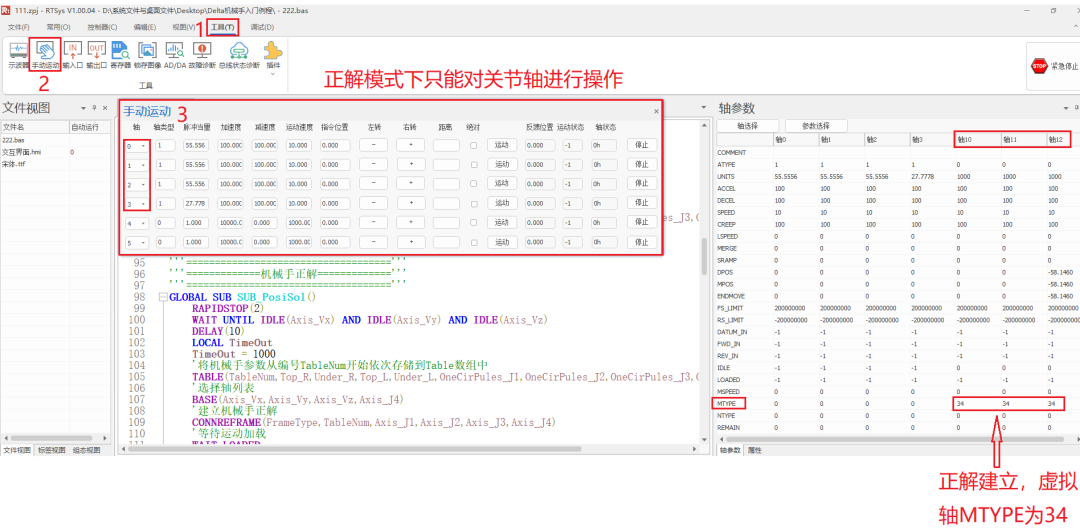
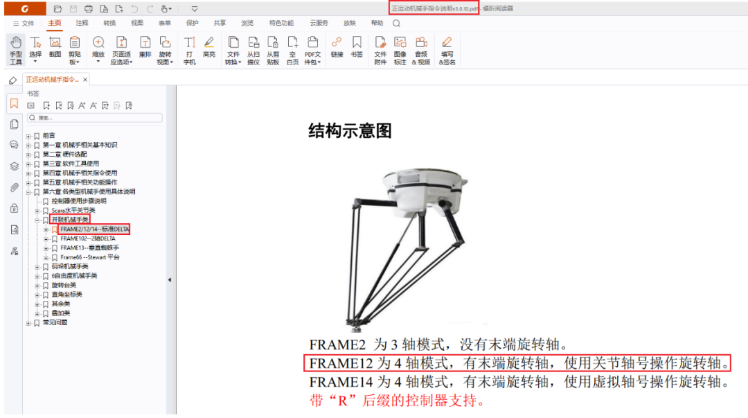
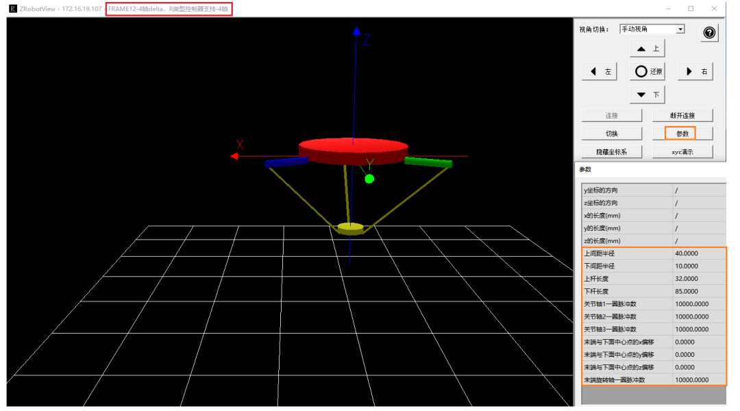
Taking the Frame12 model of the Delta robot as an example. First, store the robot structure parameters from a certain Table starting number sequentially into the Table array, then select the corresponding model’s axis list and use the CONNFRAME instruction to establish the inverse kinematics mode. Instruction descriptions can be found by searching for CONNFRAME in the 【Common】 – 【Help Document】 – 【RTBasic Help】 – 【Index】 section of the RTSys software menu.
'Store the robot parameters sequentially from the number TableNum into the Table array TABLE(TableNum,Top_R,Under_R,Top_L,Under_L,OneCirPules_J1,OneCirPules_J2,OneCirPules_J3,Offset_X,Offset_Y,Offset_Z,OneCirPules_J4)' Select axis list BASE(Axis_J1,Axis_J2,Axis_J3,Axis_J4) 'Establish robot inverse kinematics CONNFRAME(FrameType,TableNum,Axis_Vx,Axis_Vy,Axis_Vz,Axis_J4)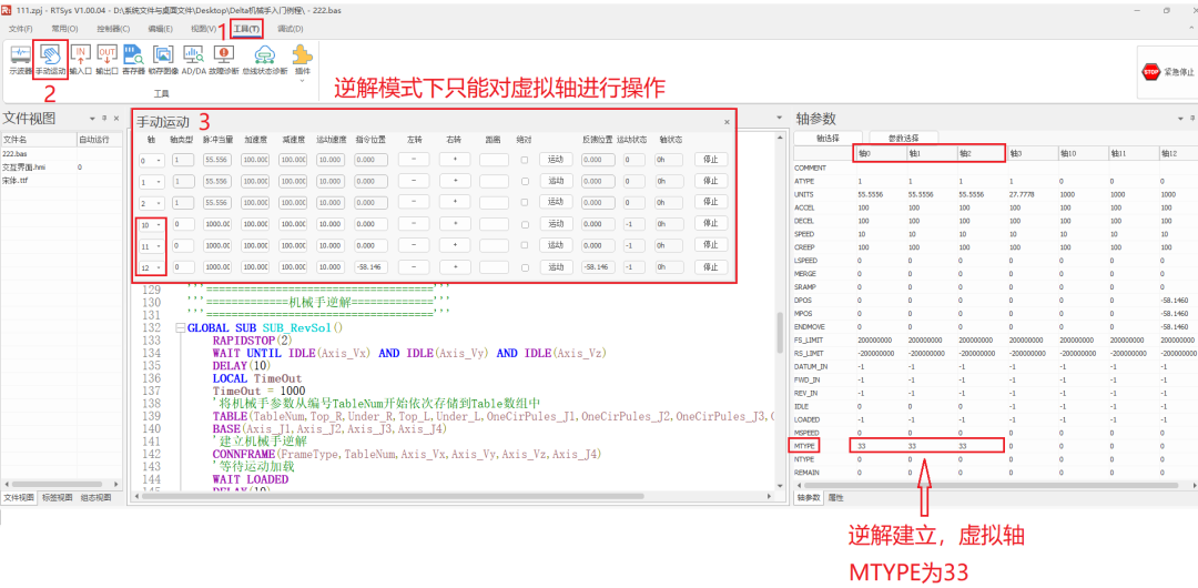
▶▶▶
Program Editing
RTSys software supports mixed programming of Basic, HMI, and PLC. This example uses Basic combined with HMI interface for demonstration. You can drag and drop controls to design the interactive interface through the 【HMI】 – 【Toolbox】 in the RTSys software menu.
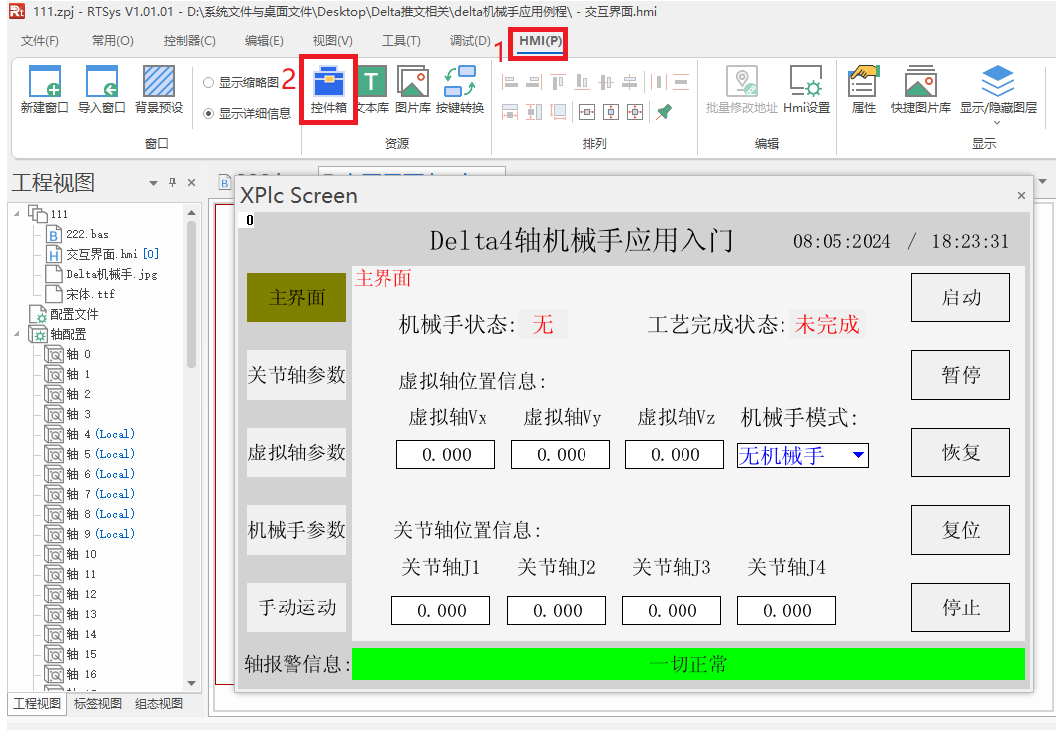
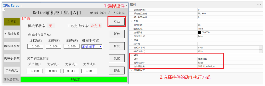
In this example, global SUB functions are defined in the bas file first, and the functionality of the sub-functions (engineering source code can be seen at the end of the article) is edited and then bound to the controls, with the actions of the controls calling the functions. The operation flow is shown in the figure below.
▶▶▶
Application Example
1. Requirement Description
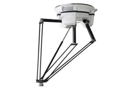
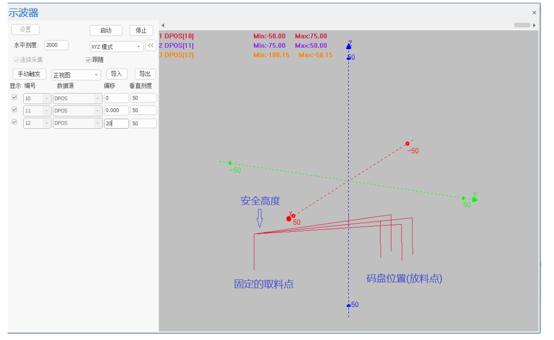
The Delta robot establishes inverse kinematics with the zero position as a reference, determining a safe height. The basic action is for the robot to rise to a safe height above the fixed picking point, then descend to open the Op port and pick up the material using vacuum suction, delay and raise to a safe height, then move to the fixed 2*2 pallet position, descend to the pallet position to close the Op for unloading, and then raise and repeat until the pallet is full and then stop.
'Start flag position 1 StartFlag = 1 LOCAL SafeHigh,i' Safe height SafeHigh = DPOS(Axis_VList(2))-25' Row, Column LOCAL Row,Col' Fixed picking point position LOCAL SrcBorrow_X,SrcBorrow_Y,SrcBorrow_Z SrcBorrow_X = 5 SrcBorrow_Y = 5 SrcBorrow_Z = SafeHigh-20' Select virtual axis BASE(Axis_VList(0),Axis_VList(1),Axis_VList(2))' Set processing speed, acceleration, deceleration SPEED = SpeedVList(0) ACCEL = AccelV(0) DECEL = DecelV(0)' Open continuous interpolation MERGE = ON' Reset temporary total count TmpSum = 0' Move to zero position reference safe height MOVEABS(0,0,SafeHigh) FOR Col=1 TO 2 FOR Row=1 TO 2 ' Move to above the picking point MOVEABS(SrcBorrow_X,SrcBorrow_Y,SafeHigh) ' Descend to the picking point MOVEABS(SrcBorrow_X,SrcBorrow_Y,SrcBorrow_Z) ' Open Op port to suck and pick MOVE_OP(8,ON) ' Delay MOVE_DELAY(300) ' Rise to safe height MOVEABS(SrcBorrow_X,SrcBorrow_Y,SafeHigh) ' Move to the unloading point above the pallet MOVEABS(-5*Row,5*Col,SafeHigh) ' Descend to the pallet unloading position MOVEABS(-5*Row,5*Col,SrcBorrow_Z) ' Close Op port for unloading MOVE_OP(8,OFF) ' Delay MOVE_DELAY(300) ' Rise to safe height MOVEABS(-5*Row,5*Col,SafeHigh) ' Increment temporary total count TmpSum = TmpSum+1 NEXT NEXT' Wait for all axes to stop WAIT UNTIL IDLE(Axis_VList(0)) AND IDLE(Axis_VList(1)) AND IDLE(Axis_VList(2)) DELAY(10) RAPIDSTOP(2) DELAY(10)' Start flag position 0 StartFlag = 0▶▶▶
Debugging Analysis
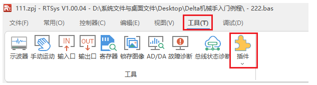
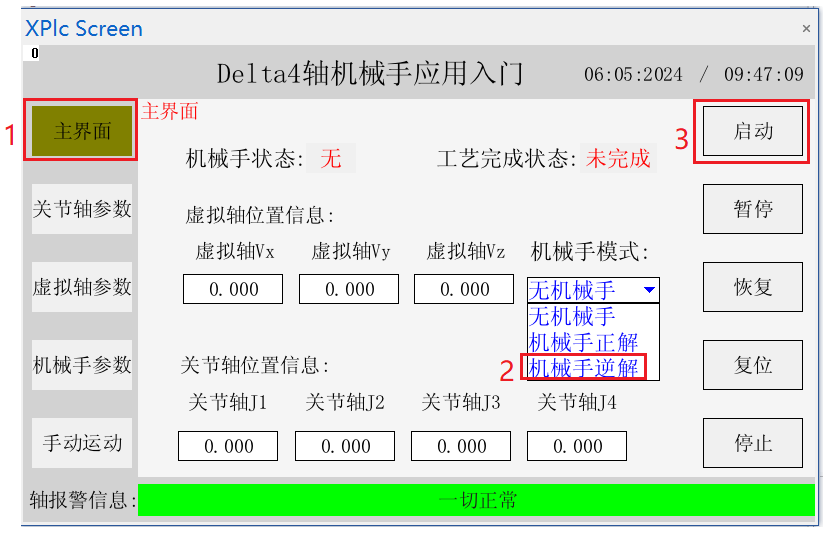
1. Download the program to the controller and click on the RTSys software menu bar 【Tools】 – 【Plugin】 – 【XPLC SCREEN】 in sequence.
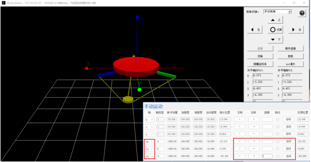
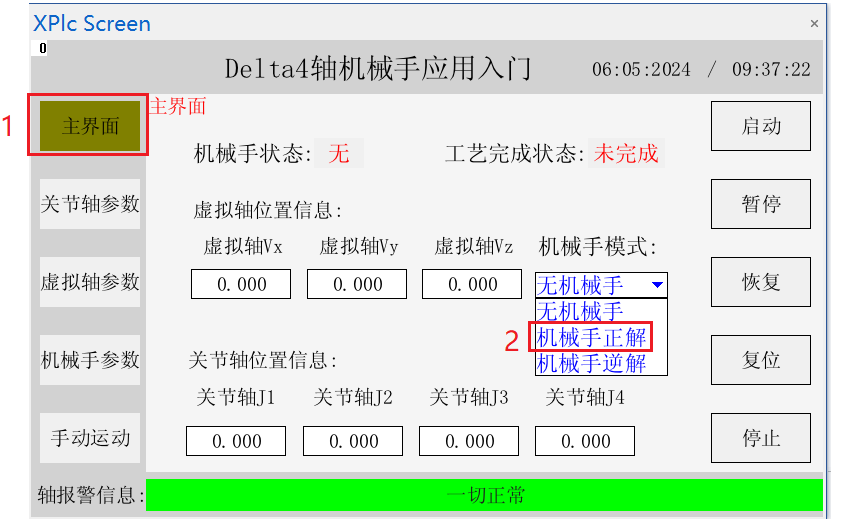
2. After the interactive interface pops up, select “Robot Forward Kinematics” in the main interface.
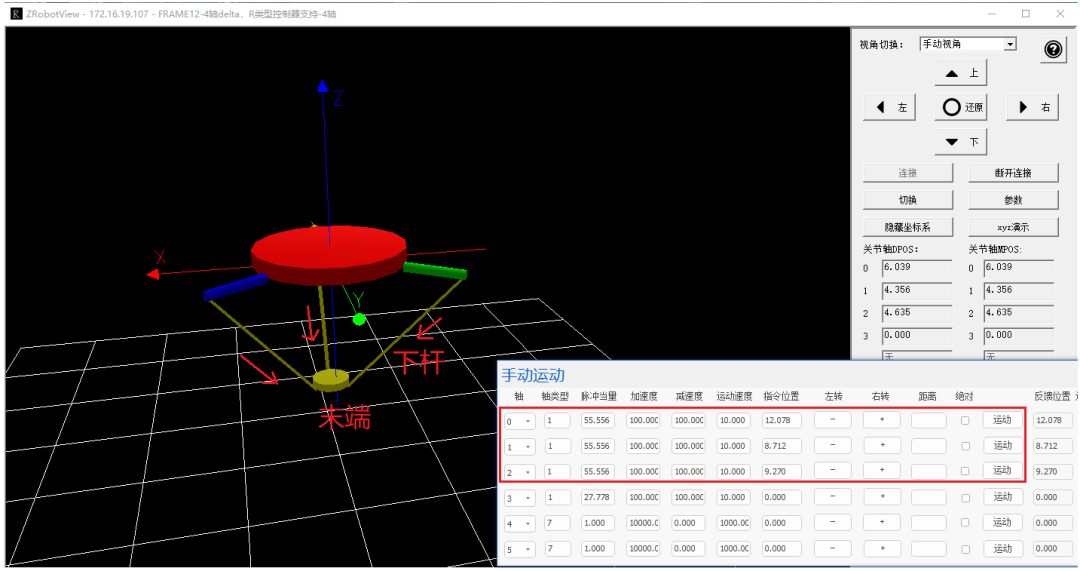
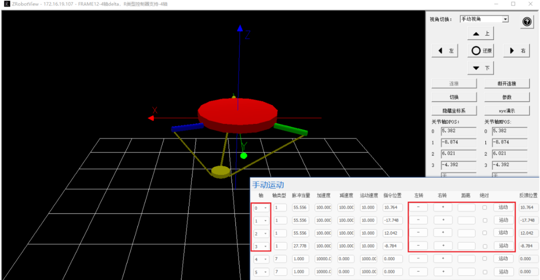
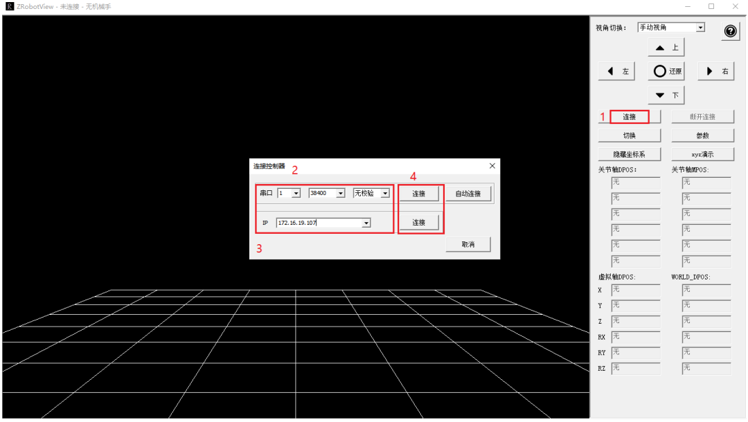
3. After establishing the forward kinematics connection, open the Positive Motion Robot Simulation Software ZRobotView, click “Connect” to pop up the “Connect Controller” window, then select the connection method (the simulation tool supports serial and network connections). Here, taking network connection as an example, select the controller’s IP in the IP field and then connect.
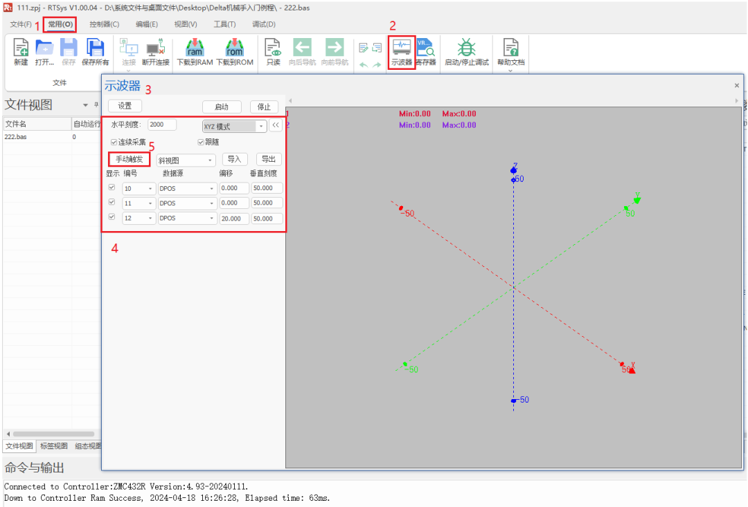
5. Switch to the RTSys programming software, click 【Common】 – 【Oscilloscope】 in sequence. After the oscilloscope window pops up, select XYZ mode to observe the action demonstration effect in three-dimensional space. Choose DPOS (planned position) as the data source, and select the virtual axis number as the data source number. After confirming the oscilloscope parameters, click 【Stop】 – 【Start】 – 【Manual Trigger】 in sequence.
Complete Code Access Address

This time, the application of Positive Motion Technology EtherCAT Motion Controller Delta Robot is shared here.
For more exciting content, please follow the “Positive Motion Assistant” public account. For related development environments and example codes, please consult Positive Motion Technology sales engineers: 400-089-8936.
About Positive Motion Technology
Shenzhen Positive Motion Technology Co., Ltd. was established in 2013, focusing on the research of purely domestic motion control technology and the development of general motion control software and hardware platforms and products. It is a national high-tech and specialized “Little Giant” enterprise.
Positive Motion Technology gathers excellent talents from companies such as Huawei and ZTE. Striving for innovation, the company currently holds more than fifty intellectual property rights such as patents and copyrights. While insisting on independent innovation, it actively collaborates with major universities and research institutes to jointly research the basic technology of motion control, making it one of the fastest-growing enterprises in the domestic industrial control field, and one of the few enterprises that fully master core motion control technology and real-time industrial control software platform technology.
In addition to the main R&D center, Positive Motion Technology has three R&D branches in Zhongshan, Wuhan, and Shanghai. To better serve customers, it has two regional service centers outside the headquarters, and has sales and technical service institutions in Foshan, Xiamen, Qingdao, Xi’an, Wuhan, Chengdu, Tianjin, Zhengzhou, and other places.
After years of development applications with numerous partners, Positive Motion Technology’s products are widely used in fields such as 3C electronics, semiconductors, new energy, robots, packaging and printing, textile and clothing, laser processing, medical and pharmaceutical, CNC machine tools, and traditional processing.