When using PROTEUS for simulation, the pins of each component can be connected directly with wires, labeled connections, or using a “bus”.
In the PROTEUS component library, some components have pins that are connected in a “bus” format, such as the 8031, 8155, 8255, etc.
Therefore, for these components, the connections must be made using a “bus”, and the bus must also have the appropriate bus-type labels; only with these labels can the bus connect to the internal circuits of the component.
The figure below shows the connection between the 51 microcontroller and the 8155, illustrating the circuit diagram for expanding three parallel interfaces in the microcontroller system.
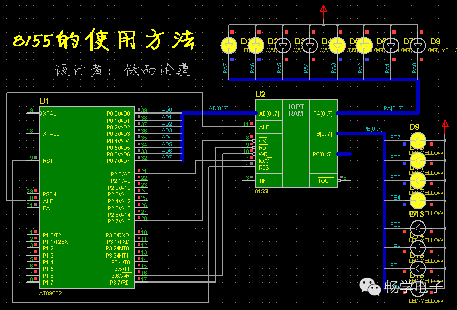
The 8155 in the diagram is used as external RAM. Once the address is determined, writing the driver program is straightforward.
First, initialize, then output two bytes of data through PA and PB. The complete code is as follows:
COMMANDEQU7F00H
PORTAEQU7F01H
PORTBEQU7F02H
PORTCEQU7F03H
ORG0000H
LJMPMAIN
ORG0080H
MAIN:
MOVDPTR,#COMMAND
MOVA,#00000011B;PA mode 0 output, PB mode 0 output
MOVX@DPTR,A
INCDPTR; move to PA
MOVA,#00110011B; data
MOVX@DPTR,A; output
INCDPTR; move to PB
MOVA,#00001111B; data
MOVX@DPTR,A; output
LJMP$
END
The original question is as follows:
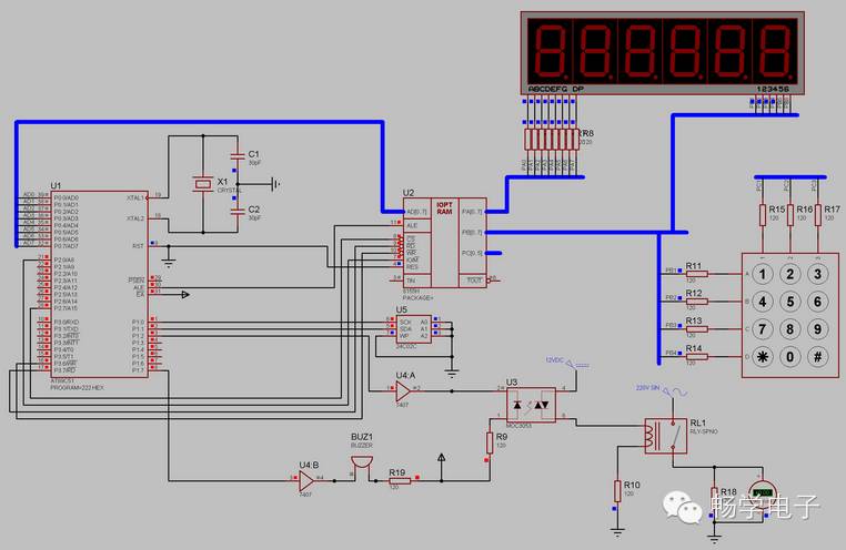
【Question】The 89C51 microcontroller expands the 8155 chip in PROTEUS simulation, but the seven-segment display does not show.
The program is as follows:
ORG0000H
COMMAND EQU 7F00H
PORTA EQU 7F01H
PORTB EQU 7F02H
PORTC EQU 7F03H
LJMPMAIN
ORG0080H
MAIN:
MOVSP,#0030H
MOVDPTR,#COMMAND
MOVA,#00000011B; set to mode 0 and PA output, PB output
MOVX@DPTR,A
INCDPTR
MOVA,#00110011B; test common anode 7-segment display
MOVX@DPTR,A
INCDPTR
MOVA,#00001111B
MOVX@DPTR,A
LJMP$
END
However, during simulation, none of the six seven-segment displays show anything, which is puzzling. I seek guidance.
【Answer】
The circuit is not drawn carefully, and the bus labels are not marked.
On the thick blue line, labels such as AD[0..7], PA[0..7], etc., should be marked.
Only then can the bus connect correctly with the internal labels of the 8255 device.
Check the examples provided with the PROTEUS software to understand.
Based on the author’s circuit, I adjusted the component layout and added bus labels;
without changing a single line of the program, the desired output was achieved.
Please refer to the usage diagram of the 8155.