Click the card below to follow Arm Technology Academy
The OS can support multitasking, periodically completing context switches, and processing tasks in a parallel architecture, where a single task crash will not affect the entire system. Periodic context switching requires a timer to interrupt program execution, and the SysTick timer can provide the necessary clock pulses to provide a rhythmic “heartbeat” for the OS task scheduling.
The SysTick timer, also known as the system tick timer or “heartbeat timer”, is a 24-bit countdown timer that automatically reloads the initial value from the reload register when it counts down to zero. As long as the enable bit in the SysTick control and status register is not cleared, it will run continuously, even in sleep mode.
The SysTick timer is bundled in the NVIC to generate SysTick exceptions (exception number: 15), and the priority of the SysTick interrupt can also be set.
It works based on the beats, dividing the entire time period into many small time slices, where each task can only run for the length of one time slice, and will exit to allow other tasks to run if it times out, ensuring that no single task monopolizes the various timing functions provided by the operating system, all of which are related to this tick timer.
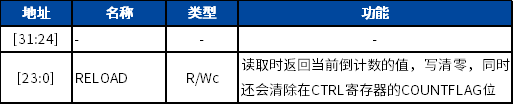
When enabled, the timer counts down from the reload value to zero, and in the next clock cycle, it reloads the value in SYST_RVR, and then counts down in subsequent clock cycles. Writing a zero value to SYST_RVR will disable the counter on the next callback. When the counter reaches zero, the COUNTFLAG status bit is set to 1. Reading SYST_CSR will clear the COUNTFLAG bit to 0. Writing to SYST_CVR will clear both the register and the COUNTFLAG status bit to 0, writing will not trigger the SysTick exception logic, and reading this register will return its value upon access.
1. SysTick Registers
The SysTick timer consists of 4 main registers:
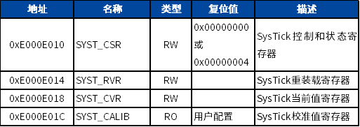
The structure of system control registers in CMSIS:
typedef struct
{  __IO uint32_t CTRL; /*!< Offset: 0x00  SysTick Control and Status Register */
  __IO uint32_t LOAD; /*!< Offset: 0x04  SysTick Reload Value Register       */
  __IO uint32_t VAL;  /*!< Offset: 0x08  SysTick Current Value Register      */
  __I  uint32_t CALIB;/*!< Offset: 0x0C  SysTick Calibration Register        */
} SysTick_Type;
In the official Arm documentation, the four registers are named SYST_CSR, SYST_RVR, SYST_CVR, and SYST_CALIB, but in CMSIS, they are simplified for clarity.
1.1. SysTick Control and Status Register (SYST_CSR)
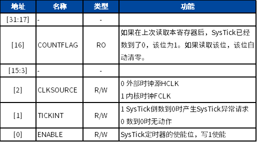
The CSR register uses 4 bits: bit0 is used to enable or disable the timer, setting it to 1 enables the SysTick timer; bit1 controls whether to generate an interrupt, setting it to 1 allows interrupts; bit2 sets the clock source for the timer, setting it to 1 uses the main clock, while setting it to 0 uses one-fourth of the main clock.
The HCLK source of the SysTick in the MM32F0130 series comes from the AHB bus after a hardware division by 4, while FCLK comes directly from the AHB clock bus.
When the SysTick timer counts down from 1 to 0, it sets the COUNTFLAG bit;
and the following methods can clear it:
-
Read the SysTick control and status register (STCSR)
-
Write any data to the SysTick current value register (STCVR)
1.2. SysTick Reload Value Register (SYST_RVR)
The RVR register uses bits 0-23, this value is the initial value for the timer countdown, after enabling the timer, it will count down from the value set here to 0, and then start counting down again from this value.
1.3. SysTick Current Value Register (SYST_CVR)
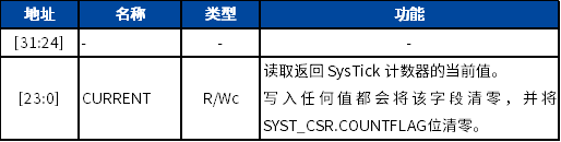
The CVR register also uses bits 0-23, this is a status register, when the timer starts operating, this value keeps changing, counting down to 0 from the initial value obtained from the RVR register.
CURRENT: Reading this register returns the current value of the system timer, writing a value to this register will set the timer to 0 and clear the COUNTFLAG bit in CTRL.
1.4. SysTick Calibration Register (SYST_CALIB)
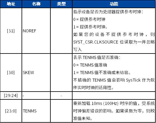
If the calibration information is unknown, the required calibration value can be calculated based on the processor clock or external clock frequency.
The calibration value register provides a solution: it allows the system to produce a constant SysTick interrupt frequency even when running on different CM0 products. The simplest approach is to directly write the value of TENMS to the reload register, which allows for a SysTick exception every 10ms as long as the system limits are not exceeded. If other SysTick exception periods are needed, they can be calculated proportionally based on the value of TENMS.
Among the four registers of the system timer, SYST_CALIB is the calibration register, which has been configured before leaving the factory, so we do not need to consider this register.
2. SysTick Programming
SysTick configuration needs to follow a certain process:
-
Start
-
Disable SysTick
-
Set reload value register
-
Clear current value register
-
Enable SysTick
-
Complete
Functions related to SysTick operations include:
__STATIC_INLINE uint32_t SysTick_Config(uint32_t ticks);
void SysTick_CLKSourceConfig(u32 systick_clk_source);
void RCC_SystickDisable(void);
void RCC_SystickEnable(u32 sys_tick_period);
The following code demonstrates a basic program to enable SysTick:
; Enable SysTick timer and SysTick exception
LDR R0, =0xE000E010    ; Load the address of STCSR
MOV R1, #0
STR R1, [R0]           ; First stop SysTick to prevent unexpected exception requests
LDR R1, =0x3FF         ; Let SysTick count to zero every 1024 cycles. Since it counts from 1023 to 0, a total of 1024 cycles, so the load value is 0x3FF
STR R1, [R0,#4]        ; Write the reload value
STR R1, [R0,#8]        ; Write any number to STCVR to ensure COUNTFLAG is cleared
MOV R1, #0x7           ; Select FCLK as the clock source and enable SysTick and its exception request
STR R1, [R0]           ; Write value to enable timer
In the CMSIS library, there are defined configuration functions:
__STATIC_INLINE uint32_t SysTick_Config(uint32_t ticks)
{
    /* Reload value impossible */
    if ((ticks - 1UL) > SysTick_LOAD_RELOAD_Msk) {
        return (1UL);
    }
/* set reload register */
    SysTick->LOAD  = (uint32_t)(ticks - 1UL);
/* set Priority for Systick Interrupt */
    NVIC_SetPriority (SysTick_IRQn, (1UL << __NVIC_PRIO_BITS) - 1UL);
/* Load the SysTick Counter Value */
    SysTick->VAL   = 0UL;
/* Enable SysTick IRQ and SysTick Timer */
    SysTick->CTRL  = SysTick_CTRL_CLKSOURCE_Msk |
                     SysTick_CTRL_TICKINT_Msk   |
                     SysTick_CTRL_ENABLE_Msk;
/* Function successful */
    return (0UL);
}
SysTick can be operated in either polling or interrupt mode; the polling program can read the SysTick control and status register and check the COUNTFLAG. If this bit is set, it indicates that the SysTick count has reached zero.
Reference program for delay in interrupt mode:
static __IO uint32_t TimingDelay;
void Delay(__IO uint32_t nTime)
{
     TimingDelay = nTime;
     while(TimingDelay != 0);
}

void SysTick_Handler(void)
{
     if (TimingDelay != 0x00)
     {
       TimingDelay--;
     }
}

int main(void)
{
     //systick clock is HCLK, interrupt interval is 1ms
     if (SysTick_Config(SystemCoreClock / 1000))
     {
         while (1);
     }
     while(1)
     {
         Delay(200);//200ms
     }
}
Reference program for delay in polling mode:
void delay_init()
{
    SysTick_CLKSourceConfig(SysTick_CLKSource_HCLK_Div4);   // Select external clock HCLK/4
    // For system clock's 1/4, actually calculating the number of SysTick's VAL decrementing for 1us
    fac_us=SystemCoreClock/4000000;
    // Represents the number of SysTick clock counts needed for each ms, that is, the number of SysTick's VAL decrementing for each millisecond
    fac_ms=(u16)fac_us*1000;
}

void delay_ms(u16 nms)
{
    u32 temp;
    SysTick->LOAD=(u32)nms*fac_ms;          // Time loading (SysTick->LOAD is 24bit)
    SysTick->VAL =0x00;           // Clear the counter
    SysTick->CTRL|=SysTick_CTRL_ENABLE_Msk ;          // Start counting
    do
    {
        temp=SysTick->CTRL;
     }while((temp&0x01)&&!(temp&(1<<16)));   // Wait for the time to reach, check if the 16th bit of CTRL (COUNTFLAG) is 1, check if the 0th bit of STRL (ENABLE) is 1
     SysTick->CTRL&=~SysTick_CTRL_ENABLE_Msk;       // Disable the counter
     SysTick->VAL =0X00;       // Clear the counter
}

void delay_us(u32 nus)
{
    u32 temp;
    SysTick->LOAD=nus*fac_us;               // Time loading
    SysTick->VAL=0x00;        // Clear the counter
    SysTick->CTRL|=SysTick_CTRL_ENABLE_Msk ;  // Start counting
    do
    {
        temp=SysTick->CTRL;
    }while((temp&0x01)&&!(temp&(1<<16)));        // Wait for the time to reach
    SysTick->CTRL&=~SysTick_CTRL_ENABLE_Msk;  // Disable the counter
    SysTick->VAL =0X00;       // Clear the counter
}
The SysTick timer can serve other purposes besides the operating system, such as time measurement, timing, or alarms.
Recommended Reading
-
Cortex-M0 Interrupt Control and System Control (Part 4)
-
Cortex-M0 Interrupt Control and System Control (Part 3)
-
Cortex-M0 Interrupt Control and System Control (Part 2)
-
Cortex-M0 Interrupt Control and System Control (Part 1)
Follow Arm Technology Academy