1. Introduction
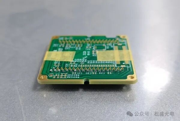
Illustration of PCB LCD Module
In the field of electronic device manufacturing, the soldering quality of PCB (Printed Circuit Board) LCD modules is crucial for product performance. As electronic products trend towards miniaturization and high performance, traditional soldering techniques are gradually showing limitations when faced with dense solder points and high precision requirements. Laser soldering technology, with its high energy density, precision, and small heat-affected zone, has become an ideal choice for soldering PCB LCD modules. In particular, the continuous wire feed laser soldering process can efficiently and stably complete the soldering of multiple points, meeting the demands of mass production. This article will delve into the technical points, process parameter optimization, and quality control aspects of continuous wire feed laser soldering for 18 solder points on PCB LCD modules.
2. Principle of Continuous Wire Feed Laser Soldering
The continuous wire feed laser soldering technology utilizes a high energy density laser beam as the heat source, which is directed at the soldering area of the PCB LCD module. The laser energy is rapidly absorbed by the material, causing the temperature in the soldering area to rise sharply, reaching the melting point of the solder wire. The solder wire is continuously fed into the soldering area and melted under the action of the feeding mechanism, filling the solder points and forming a metallurgical bond with the base material, thus achieving sequential soldering of the 18 points. Compared to traditional soldering methods, laser soldering has highly concentrated energy, fast heating speed, and a limited heat-affected zone, effectively reducing thermal damage to surrounding components, making it particularly suitable for soldering heat-sensitive precision electronic components like PCB LCD modules.
Illustration of Continuous Wire Feed Laser Soldering Process
3. Composition of Soldering Equipment and Key Components
Laser Generator: Provides a high energy density laser beam for soldering, with parameters such as power stability and beam quality directly affecting the soldering results. For the continuous soldering of 18 solder points on PCB LCD modules, a laser generator with moderate power and good beam mode should be selected to ensure rapid and uniform melting of the solder wire.
Feeding Mechanism: Precisely controls the feeding speed and amount of solder wire, ensuring stable supply during the soldering process. The response speed and accuracy of the feeding mechanism significantly impact the quality of the solder points. When continuously soldering 18 points, it is essential to synchronize the feeding speed with the laser soldering speed to avoid issues such as solder wire accumulation from excessive feeding speed or insufficient solder at the points from slow feeding speed.
Soldering Workbench: Used to support the PCB LCD module, it must have high precision positioning and motion control capabilities. During soldering, the workbench can move accurately along a preset path, allowing the laser beam to hit each solder point precisely, achieving orderly soldering of the 18 points. Additionally, the stability of the workbench is crucial to prevent vibrations during soldering from affecting the soldering quality.
Visual Positioning System: Utilizes cameras and other visual devices to obtain real-time positional information of the PCB LCD module, accurately identifying and locating the solder points. Before soldering, the visual positioning system can quickly calibrate the module’s position, ensuring the starting point for soldering is accurate; during soldering, it can monitor the quality of the solder points in real-time and dynamically adjust the soldering parameters, improving consistency and reliability.
4. Process Parameter Optimization
Laser Power: The laser power determines the energy input during the soldering process and is a key parameter affecting soldering quality. If the power is too low, the solder wire cannot melt sufficiently, leading to weak solder points and cold solder issues; if the power is too high, it may cause excessive melting of the base material, burning through, or even damaging the LCD module. For continuous wire feed laser soldering of 18 points, the appropriate laser power range should be determined through experiments based on factors such as solder wire material, diameter, and PCB thickness, and maintained stable during soldering.
Soldering Speed: The soldering speed works in conjunction with laser power to influence heat input and solder point formation. A soldering speed that is too fast may result in insufficient melting of the solder wire, leading to inadequate filling of the solder points; conversely, a speed that is too slow can cause excessive heat accumulation, enlarging the heat-affected zone and affecting the performance of surrounding components. In actual soldering, the soldering speed should be optimized based on the number and distribution of solder points and production efficiency requirements, ensuring each solder point achieves good soldering quality.
Feeding Speed: The feeding speed should be adapted to the laser power and soldering speed, ensuring that the solder wire can be filled into the solder points timely and accurately while being melted by the laser. If the feeding speed is too fast, the solder wire will accumulate in the soldering area, forming solder lumps; if too slow, it will lead to insufficient solder at the points. By adjusting the feeding mechanism, the optimal feeding speed that matches other parameters can be found, which is crucial for the uniformity and stability of continuous soldering of 18 points.
Defocus Amount: The defocus amount refers to the distance between the laser focus and the soldering surface. An appropriate defocus amount can help the laser beam form an ideal spot shape and energy distribution on the soldering surface, improving soldering quality. Positive defocus results in a larger spot area with relatively lower energy density, suitable for soldering thinner materials; negative defocus results in a smaller spot area with higher energy density, suitable for soldering thicker materials. For PCB LCD module soldering, the defocus amount should be adjusted based on specific conditions to achieve the best soldering effect.
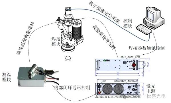
Illustration of Songsheng Optoelectronics Constant Temperature Laser Soldering System
The Songsheng Optoelectronics laser constant temperature soldering system consists of a real-time temperature feedback system, a CCD coaxial positioning system, and a semiconductor laser; it features an innovative PID online temperature adjustment feedback system that effectively controls constant temperature soldering, providing real-time high-precision control of the temperature of the soldering object, ensuring high yield and precision in soldering. It is especially suitable for high-precision soldering processes that are sensitive to temperature, such as micro speakers/motors, connectors, electronic modules, cameras, etc.
5. Soldering Quality Control
Solder Point Appearance Inspection: Through manual visual inspection or automated visual inspection equipment, the shape, size, surface flatness of the solder points, and the presence of solder lumps, pores, cracks, and other defects are observed. Qualified solder points should present a regular hemispherical shape, smooth surface, and good transition with the base material, with no obvious defects. For the continuous soldering of 18 points, it is essential to ensure that the appearance quality of each solder point is consistent and meets product standards.
Electrical Performance Testing: The completed PCB LCD module undergoes electrical performance testing, including conductivity, resistance, insulation performance, and other indicators. Testing can determine whether there are cold solder or short circuit issues in the solder points, ensuring the module can function normally in actual use. Electrical performance testing is a crucial aspect of soldering quality control, directly reflecting the impact of soldering on circuit functionality.
Metallographic Analysis: Using a metallographic microscope to analyze the microstructure of the solder points, observing the metallurgical bonding condition, grain size, and morphology. A good solder point microstructure should exhibit a uniform and dense structure, with a strong metallurgical bonding layer formed between the base material and the solder wire. Metallographic analysis helps to understand the intrinsic factors affecting soldering quality, providing a basis for process improvement.
Process Monitoring and Feedback: Utilizing sensors to monitor parameters such as temperature, laser power, and feeding speed in real-time during the soldering process, with a control system to adjust parameters dynamically. When abnormal parameters are detected, the system can promptly issue alarms and take corresponding measures to ensure the stability and reliability of the soldering process. Additionally, data from the soldering process is recorded and analyzed to support subsequent process optimization.
6. Common Issues and Solutions
Cold Solder: This manifests as poor metallurgical bonding between the solder point and the base material, leading to unreliable electrical connections. Possible causes include insufficient laser power, too short soldering time, poor feeding of the solder wire, or contamination on the surface of the workpiece. Solutions include appropriately increasing laser power, extending soldering time, checking the feeding mechanism, and cleaning the workpiece surface to ensure the soldering area is clean.
Solder Lump: Refers to the accumulation of excess solder around the solder point. This is mainly caused by excessive feeding speed, slow soldering speed, or high laser power. Adjusting the feeding speed, increasing the soldering speed, or reducing the laser power to balance the soldering parameters can effectively prevent the formation of solder lumps.
Pores: Holes appearing inside or on the surface of the solder points. This may be due to moisture or oil on the solder wire or workpiece surface vaporizing during soldering, forming gas that is not expelled in time. Sufficient drying and cleaning of the solder wire and workpiece before soldering, along with selecting appropriate soldering process parameters, such as increasing soldering speed, can help gas escape and reduce pore formation.
Burn Through: Excessive melting of the base material, resulting in perforation. This is often caused by high laser power or slow soldering speed. Reducing laser power, increasing soldering speed, and adjusting soldering parameters to appropriate ranges can prevent burn-through.
7. Conclusion
The continuous wire feed laser soldering technology for 18 solder points on PCB LCD modules has significant application value in modern electronic manufacturing. By deeply understanding the soldering principles, optimizing key components of the soldering equipment, reasonably adjusting process parameters, and implementing effective quality control measures, common issues in the soldering process can be resolved, achieving high-quality and high-efficiency soldering. With the continuous development and improvement of laser technology, continuous wire feed laser soldering will play a greater role in the manufacturing of PCB LCD modules and other electronic fields, advancing electronic product manufacturing towards higher precision and reliability.
Note
If you like this article, please share it with your friends. For more information, please follow us.

Long press the QR codeto follow us


Address: Room 502, 5th Floor, Building 9, Gezhouba Sun City, No. 4 Gaoxin Road, East Lake New Technology Development Zone, Wuhan, Hubei Province
Phone: 13971100349
E-mail: [email protected]
Website: https://www.whlaser.cn
Postal Code: 430074