
Internet
 Internet
The Internet is the largest network in the world today, known as the “network of networks”. It is a massive network that interconnects all other networks.
The components of the Internet:
-
Edge part: Host
-
Core part: A large number of networks and the routers connecting these networks (this router is not the one used at home)
Ethernet
Ethernet is the most commonly used local area network communication protocol today, and it transmits MAC frames. Since Ethernet allows only one computer to send data at a time, a detection mechanism must be in place, which is the CSMA/CD protocol:
-
Multiple access: Multiple computers connect to a single bus
-
Carrier sensing: Each station must continuously monitor the channel, regardless of whether it is transmitting
-
Collision detection: Listen while sending
OSI
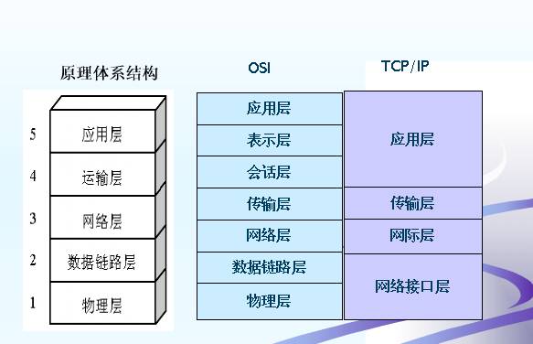
The Open Systems Interconnection basic reference model allows any two systems to communicate as long as they comply with the OSI standard. The OSI is a seven-layer protocol architecture, while TCP/IP is a four-layer protocol architecture. Thus, we often use a five-layer protocol architecture when studying computer network principles: physical layer, data link layer, network layer, transport layer, and application layer.
Protocol architecture
Physical Layer
In the world of computers, there are only 0s and 1s, just like the text you are reading now is stored in the computer as a long string of 0s and 1s. However, these numbers cannot be transmitted in real physical media and need to be converted into optical or electrical signals, so this layer is responsible for converting these bit streams (0101) into optical signals.
If there were no physical layer, then there would be no Internet, and no data sharing, because data would not be able to flow across the network.
Data Link Layer
Data is no longer transmitted in the form of bit streams at this layer but is segmented into individual frames for transmission.
MAC Address
Also known as the hardware address of the computer, it is a 48-bit address that is hard-coded in the adapter (network card) ROM. The MAC address can uniquely identify a computer because it is unique worldwide.
Packet Switching
Since data needs to be segmented into individual frames, and different links have different maximum frame lengths, known as MTU (Maximum Transmission Unit), any frame exceeding this MTU must be fragmented. For example, if a truck can transport 5 tons of goods at once, but a road has a weight limit of 2 tons, then you must transport it in three trips.
Bridge
A bridge operates at the data link layer and forwards and filters received frames based on the destination MAC address.
Ethernet Switch
Essentially a multi-interface bridge, each interface of the Ethernet switch is directly connected to a single host or another hub, making it easy to implement VLAN (Virtual Local Area Network).
Ethernet MAC Frame
The format of a MAC frame is as follows:
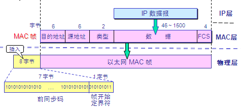
MAC frame format
-
Destination Address: 48-bit MAC address of the receiver
-
Source Address: 48-bit MAC address of the sender
-
Type Field: Indicates what protocol is being used at the upper layer, 0×0800 for IP datagrams
Network Layer
If there is only a data link layer and no network layer, data can only be transmitted on the same link and cannot be transmitted across links. With the network layer, data can be transmitted across different data links.
IP Address
An IP address, also known as a software address, is stored in the computer’s memory, with IPv4 addresses being 32 bits and IPv6 addresses being 128 bits.
IP Address and MAC Address
-
IP addresses are used above the network layer, while MAC addresses are used below the data link layer
-
IP addresses are logical addresses, while MAC addresses are physical addresses
-
The source and destination addresses in the IP packet header do not change during transmission, while the source and destination addresses in the MAC frame header change at each router
IP Address Classification
IP Address = {
Class A Address: 0.0.0.0 ~ 127.0.0.0 Class B Address: 128.0.0.0 ~ 191.255.0.0 Class C Address: 192.0.0.0 ~ 223.255.255.0
IP Address After Subnetting
IP Address = {
For example, if an organization has a Class B IP address of 145.13.0.0, any datagram with a destination address of 145.13.x.x will be sent to the router R on this network. After internal subnetting, it becomes: 145.13.3.0, 145.13.7.0, 145.13.21.0. However, it still appears as a single network externally, i.e., 145.13.0.0. Thus, when router R receives a message, it forwards it to the corresponding subnet based on the destination address.
Subnet Mask
Generally made up of a string of 1s and a string of 0s, regardless of whether the network has been subnetted, the subnet mask and IP address can be used to derive the network address by performing a bitwise AND operation.
All networks must use a subnet mask, and there must be a subnet mask column in the routing table. If a network does not subnet, then the subnet mask for that network is the default subnet mask.
The default subnet mask for Class A addresses is 255.0.0.0, for Class B addresses is 255.255.0.0, and for Class C addresses is 255.255.255.0.
Although subnetting increases flexibility, it reduces the total number of hosts that can connect to the network.
IP Address Constituting a Supernet
IP Address = {
Using network prefixes, Classless Inter-Domain Routing (CIDR)
For example, 128.14.35.7/20 means the first 20 bits are the network prefix, and the last 12 bits are the host number. Additionally, CIDR groups contiguous IP addresses with the same network prefix into a “CIDR address block”.
Address Mask: CIDR uses a 32-bit address mask, similar to a subnet mask.
IP Datagram
At the network layer, data is transmitted in the form of IP datagrams (IP packets).
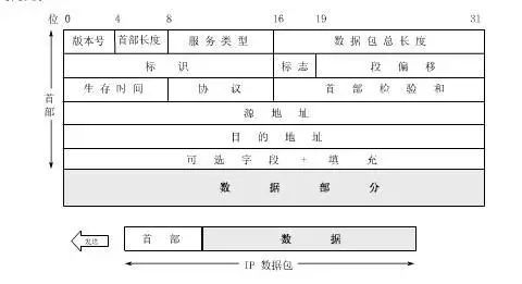
IP datagram format
The first 20 bytes of the header are of fixed length and are essential for all IP datagrams. The last 4 bytes are optional fields with variable length.
Analysis of the fixed fields in the IP datagram header:
-
Version: The version of the IP protocol, either IPv4 or IPv6
-
Header Length: Records the length of the header, with a maximum of 1111, i.e., 15 32-bit words, or 60 bytes. When the header length is not a multiple of 4 bytes, padding fields must be used for completion.
-
Type of Service: Generally unused
-
Total Length: The length of the header and data combined. The maximum is 216-1 = 65535 bytes. However, since the data link layer specifies a maximum length for each frame, the Ethernet specifies an MTU of 1500 bytes, so datagrams exceeding this range must be fragmented.
-
Identification: Every time an IP datagram is generated, a counter increments by 1, and this value is assigned to the identification field. In subsequent datagrams that need to be fragmented, the same identification indicates they are part of the same datagram.
-
Flags: Occupies 3 bits, with the lowest bit marked as MF (More Fragment). If MF = 1, it indicates there are more fragments; if MF = 0, it indicates this is the last fragment. The middle bit is marked as DF (Don’t Fragment), meaning fragmentation is not allowed. Fragments are only allowed when DF = 0.
-
Fragment Offset: Also known as the fragment offset, indicates where this fragment starts relative to the user data field. The fragment offset is measured in units of 8 bytes. Therefore, the length of each fragment must be a multiple of 8 bytes.
-
Time to Live: TTL (Time To Live). The maximum number of times a datagram can pass through routers on the Internet is 255. Each time it passes through a router, TTL is decremented by 1, and when it reaches 0, the datagram is discarded.
-
Protocol: Records what protocol is used for the data carried by this datagram.
-
Header Checksum: Only checks the header of the datagram, not the data part. If it is not 0, the datagram is discarded.
-
Source and Destination Addresses: No explanation needed
IP Layer Forwarding Process
Every router maintains a routing table, which contains the following information (destination network address, next hop address).
When using subnets for packet forwarding, the routing table must contain the following three items: destination network address, subnet mask, and next hop address.
Specific Host Routing: Specifies a route for a specific destination address
Default Route: When unsure of which router to send the packet to, it is sent to the default route. This is very suitable for a network with very few external connections.
Router Packet Forwarding Algorithm
-
Obtain the destination IP address D from the datagram to derive the destination network address N
-
If N is a network address directly connected to this router, deliver it directly (no need to forward it to other routers, just deliver it to the destination host), otherwise -> (3)
-
If the routing table has a specific host route for the destination address D, forward the datagram to that router, otherwise -> (4)
-
If the routing table has a route to network N, forward the datagram to that router, otherwise -> (5)
-
If the routing table has a default route, forward it to that router, otherwise -> (6)
-
Report an error in forwarding the packet
Virtual Private Network (VPN)
All routers on the Internet do not forward datagrams with private addresses. There are three types of private addresses (virtual IP addresses):
-
10.0.0.0 ~ 10.255.255.255
-
172.16.0.0 ~ 172.31.255.255
-
192.168.0.0 ~ 192.168.255.255
Assuming that Company A has a department in Guangzhou and another in Shanghai, and they both have their own private networks locally. How can these two private networks be connected?
-
Renting a communication line from a telecom company for exclusive use is too expensive
-
Using the public Internet as a communication carrier, this is the Virtual Private Network (VPN)
Network Address Translation (NAT)
Multiple hosts within private networks share a single IP address of a NAT router. When hosts send and receive IP datagrams, they must first go through the NAT router for network address translation.
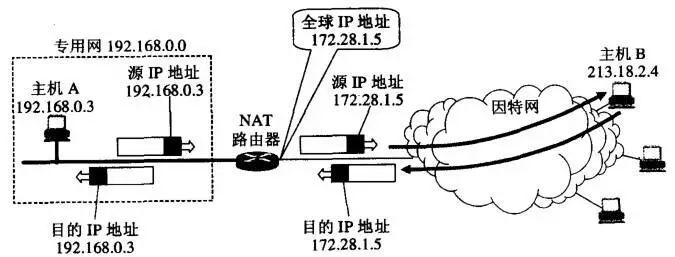
The working principle of the NAT router
Moreover, NAT can also use port numbers to transform into Network Address and Port Translation (NAPT).
ARP Protocol
ARP solves the mapping problem between the IP address and MAC address of hosts or routers on the same local area network, i.e., IP address -> ARP -> MAC address.
Each host has an ARP cache, which contains a mapping table of IP addresses to MAC addresses for all hosts and routers in the local area network. The following illustrates the working principle of ARP:
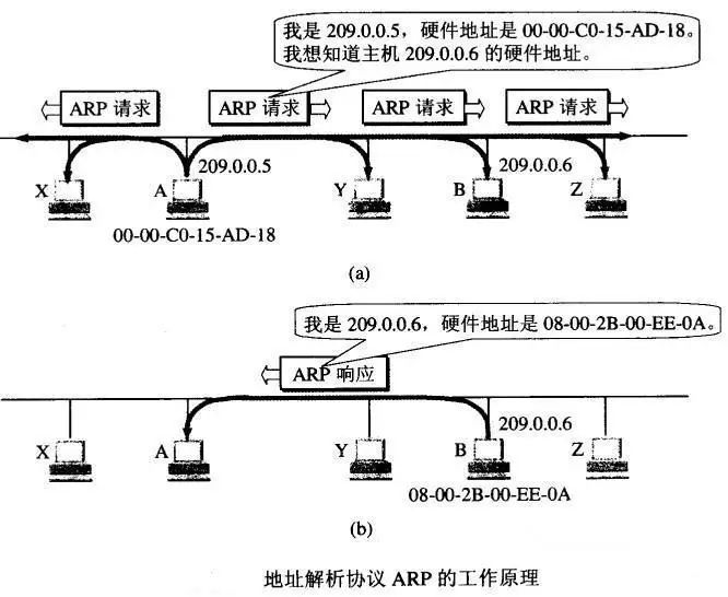
Working principle of ARP.jpg
What if ARP is used across networks?
-
Broadcast on the local network
-
If the host is not found, then go to the router
-
The router helps forward (broadcast on another network)
-
If found, complete the ARP request; if not found, return to (2)
Transport Layer
This layer is crucial because the data transmission of the data link layer and network layer is unreliable and only attempts to deliver to the best of its ability. What does this mean? It means they do not guarantee that the data delivered to you is correct. However, this layer’s TCP protocol will provide reliable transmission.
This layer mainly focuses on two protocols: UDP and TCP.
User Datagram Protocol (UDP)
Main features of UDP:
-
Connectionless
-
Best effort delivery
-
Message-oriented: The message handed down from the application layer is directly appended with a UDP header and thrown to the IP layer without merging or splitting
-
No congestion control
-
Supports one-to-one, one-to-many, many-to-one, and many-to-many interactive communication
-
Small header overhead, only 8 bytes
UDP Header

UDP header format
-
Source Port: Source port number. Used when a reply is needed; otherwise, it is all 0
-
Destination Port: Destination port number. This must be used when delivering the message at the destination
-
Length: Length of the UDP datagram, with a minimum value of 8 (only the header)
-
Checksum: Unlike IP datagrams, which only check the header, UDP checks both the header and the data part
Transmission Control Protocol (TCP)
Main features of TCP:
-
Connection-oriented transport layer protocol
-
Each TCP connection can only have 2 endpoints; TCP is point-to-point
-
Provides reliable delivery
-
Full-duplex communication
-
Byte stream-oriented
TCP Workflow
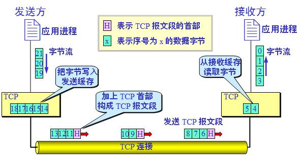
TCP byte stream
TCP Connection
The endpoints of a TCP connection are called sockets.
socket = (IP address : port number)
Each TCP connection is uniquely determined by the two endpoints (sockets) at both ends of the communication. That is:TCP connection ::= {socket1, socket2} = {(IP1 : port1), (IP2 : port2)}
TCP Segment Header
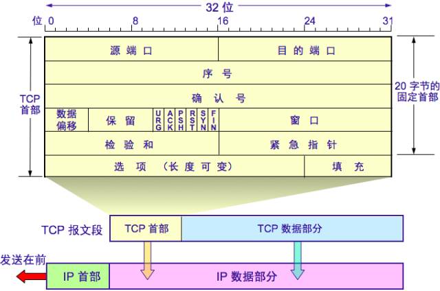
TCP segment header
-
Source Port and Destination Port: Same function as UDP ports
-
Sequence Number: The sequence number of the first byte of data in this segment
-
Acknowledgment Number: The expected sequence number of the first data byte of the next segment to be received
<span>If acknowledgment number = N, it indicates that all data up to sequence number N-1 has been received correctly</span> -
Data Offset: The length of the TCP segment header
-
Reserved: For future use, currently 0
-
Urgent URG: If URG = 1, it indicates that the urgent pointer field is valid, signaling the system that this is urgent data and should be sent as soon as possible. For example, a sudden request to interrupt transmission
-
Acknowledgment ACK: ACK = 1 indicates that the acknowledgment number is valid; ACK = 0 indicates that the acknowledgment number is invalid. TCP stipulates that after establishing a connection, all transmitted segments must set ACK to 1
-
Push PSH: If PSH = 1, the receiving end delivers the segment immediately after receiving it without waiting for the entire buffer to fill
-
Reset RST: When RST = 1, it indicates that there is a serious error in the TCP connection, and the connection must be released and reconnected
-
Synchronize SYN: Used to synchronize sequence numbers during connection establishment. When SYN = 1 and ACK = 0, it indicates this is a connection request segment. If the other party agrees to establish a connection, it sets SYN = 1 and ACK = 1 in the response segment
-
Terminate FIN: When FIN = 1, it indicates that the sender has finished sending data and requests to release the connection
-
Window: Informs the other party of the amount of data allowed to be sent based on the acknowledgment number from this segment’s header. This serves as a basis for the receiving end to set its sending window
-
Checksum: Like UDP, checks both the header and data parts
-
Urgent Pointer: Valid when URG = 1, indicating the position of the end of the urgent data in the segment
-
Options: Maximum 40 bytes; if none, it is 0
Maximum Segment Size (MSS): Maximum length of the data field in each TCP segment; if not specified, it defaults to 536 bytes.
Window
A very important concept in TCP is the window (sending window and receiving window).
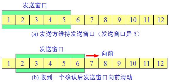
Window
Since the stop-and-wait protocol is very inefficient, the concept of the window was derived. The diagram above shows the sending window maintained by the sender; the five packets within the sending window can be sent continuously without waiting for the other party’s acknowledgment. Each time an acknowledgment is received, the sending window is moved forward one packet position. This greatly improves channel utilization!
The receiving end does not need to send an acknowledgment message for each packet but uses cumulative acknowledgment. That is, it sends an acknowledgment message for the last packet that arrives in order.
Timeout Retransmission
If the sender waits for a period of time and still does not receive the ACK acknowledgment message, it will activate the timeout retransmission. This waiting time is known as the Retransmission TimeOut (RTO).
However, the value of RTO is not fixed; this time is always slightly greater than the round-trip time (RTT). If sending a message takes 5 seconds, and the other party takes 5 seconds to send back the acknowledgment, then RTT is 10 seconds, and RTO should be slightly greater than 10 seconds. If no acknowledgment is received after exceeding RTO, it is assumed that the message is lost and must be retransmitted.
Flow Control
Flow control is implemented using sliding windows and the timing of segment transmissions.
Congestion Control
The sender maintains a congestion window (cwnd), and the sending window = congestion window.
Slow Start: cwnd = 1, then doubles after each transmission round Congestion Avoidance: cwnd increases slowly, adding 1 after each transmission round Slow Start Threshold ssthresh:
When cwnd < ssthresh, use the slow start algorithm. When cwnd > ssthresh, use the congestion avoidance algorithm. When cwnd = ssthresh, it's arbitrary.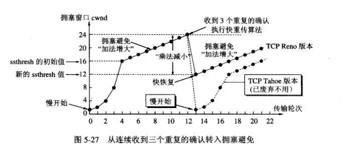
Congestion control
Whenever network congestion is detected, set ssthresh to half of the current sending congestion window (not less than 2), and set cwnd to 1, then execute the slow start algorithm again.
In addition to the slow start and congestion avoidance algorithms, there is also a set of fast retransmission and fast recovery algorithms:
Fast Retransmission: The receiver sends acknowledgment promptly, and the sender immediately retransmits upon receiving three duplicate acknowledgments Fast Recovery: When the sender receives three duplicate acknowledgments in a row, ssthresh is halved, and cwnd is set to ssthresh.
TCP Three-Way Handshake
The TCP three-way handshake for establishing a connection and the four-way handshake for disconnecting is a common interview topic.
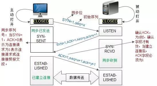
TCP three-way handshake
Q: Why three-way handshake? Can it be two?
A: Imagine that A sends a connection request for the first time, but it is delayed at some node in the network. A times out and retransmits, and this time everything goes smoothly, and A and B happily transmit data. After the connection is released, the lost connection request suddenly arrives at B. If it were a two-way handshake, B would send an acknowledgment, and they would consider the connection established. In fact, A would not care about this acknowledgment because it did not intend to send data. However, B would mistakenly think that data is coming, waiting in vain, which leads to resource wastage.
A more relatable explanation is: A is calling B
First handshake: Hello, I am A, can you hear me? Second handshake: I can hear you, I am B, can you hear me? Third handshake: I can hear you, we can start chatting now.TCP Four-Way Handshake
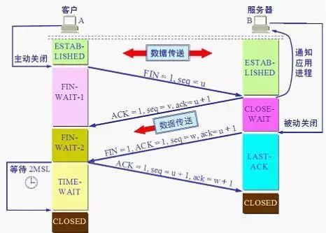
TCP four-way handshake
Q: Why four-way handshake and not two or three?
A: First, due to TCP’s full-duplex communication, both parties can act as data senders. A wants to close the connection and must wait for all data to be sent before sending FIN to B. (At this point, A is in a half-closed state.) Then, B sends an acknowledgment ACK, and if B wants to send data, it does so (e.g., for some pre-release processing). After B sends the data, it sends FIN to A. (At this point, B is in a half-closed state.) Then, A sends ACK, entering the TIME-WAIT state. Finally, after 2MSL time without receiving any messages from B, it confirms that B has received the ACK. (At this point, both A and B are in a fully closed state.)
PS: A careful analysis of the above steps reveals why it cannot be less than four-way handshake.
Q: Why wait for 2MSL time before transitioning from TIME_WAIT to CLOSED?
A: When the client sends the final ACK reply, that ACK might get lost. If the server does not receive the ACK, it will continue to send FIN segments. Therefore, the client cannot close immediately; it must confirm that the server received the ACK. The client enters the TIME_WAIT state after sending the ACK. The client sets a timer to wait for 2MSL. If it receives FIN again during this time, it will retransmit ACK and wait for another 2MSL. MSL refers to the maximum lifetime of a segment in the network; 2MSL is the maximum time required for sending and replying. If, after 2MSL, the client does not receive any more FIN messages, it concludes that the ACK has been successfully received and ends the TCP connection.
A more relatable explanation:
First handshake: A tells B, I have no data to send, preparing to close the connection, do you need to send any data? Second handshake: B sends the final data. Third handshake: B tells A, I also want to close the connection. Fourth handshake: A tells B you can close now; I will close too.Application Layer
The most famous application layer protocols are HTTP and FTP, and another important one is DNS.
Domain Name System (DNS)
DNS can resolve domain names (e.g., www.jianshu.com) into IP addresses.
Classification of DNS servers:
-
Root DNS Server: The highest-level domain name server
-
Top-Level Domain Server: As the name suggests
-
Authoritative DNS Server: Responsible for a zone’s authoritative server
-
Local DNS Server: The server to which the host sends DNS query requests
DNS Query
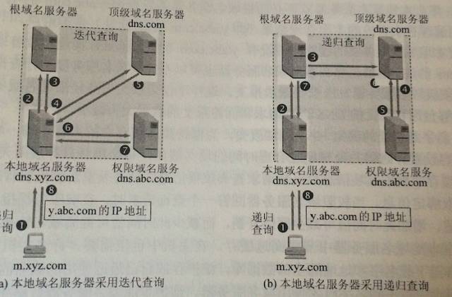
DNS Query
-
Queries from hosts to local DNS servers are generally recursive queries
-
Local DNS servers typically use iterative queries to query root DNS servers
Recursive Query: B asks A how to get to Guangzhou; A doesn't know, so A asks C, C doesn't know, so it asks D... until it knows and then passes the answer back layer by layer until A tells B. Iterative Query: B asks A how to get to Guangzhou; A doesn't know, so A tells you to ask C, then B asks C, C doesn't know, C tells you to ask D, and then B asks D... until B knows.
Example of DNS Query: A host named x.tom.com wants to know the IP address of y.jerry.com
-
Host x.tom.com first performs a recursive query to the local DNS server dns.tom.com
-
The local DNS server uses iterative queries. It first asks a root DNS server
-
The root DNS server tells it to ask the top-level domain server dns.com
-
The local DNS server queries the top-level domain server dns.com
-
The top-level domain server tells it to ask the authoritative DNS server dns.jerry.com
-
The local DNS server queries the authoritative DNS server dns.jerry.com
-
The authoritative DNS server dns.jerry.com tells it the IP address of the queried host
-
The local DNS server returns the query result to host x.tom.com
PS: This query uses UDP, and to improve DNS query efficiency, each DNS server uses caching.
URL
The format of a URL: <protocol>://<host>:<port>/<path>, where the port and path can sometimes be omitted.
Using HTTP protocol URL: http://<host>:<port>/<path>, the default port number for HTTP is 80.
HTTP Protocol
HTTP is transaction-oriented, meaning the data it transmits is a whole; either all is received or none is received.
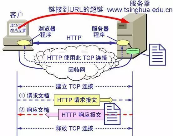
The working process of the World Wide Web
Each HTTP request requires establishing a TCP connection and releasing it.
HTTP is connectionless and stateless. Each request is treated as a new request.
HTTP/1.0 drawbacks: connectionless, requiring a new TCP connection for each request, so each HTTP request takes twice the RTT time (once for the TCP request, once for the HTTP request).
HTTP/1.1: Uses persistent connections, maintaining the TCP connection for a while.
Two modes of persistent operation in HTTP/1.1: non-pipelined and pipelined. Non-pipelined: Send the next request only after receiving a response to the previous one, which is inefficient and wastes resources. Pipelined: Allows multiple requests to be sent simultaneously, which is efficient.HTTP GET and POST
GET requests are typically used for querying and retrieving data, while POST requests are used for sending data. The parameters of GET requests are in the URL, so sensitive data should never be transmitted using GET requests, while POST request parameters are in the request header, which is slightly more secure than GET requests.
PS: The data in POST requests is also stored in plaintext in the request header, so it is also not secure.Cookie
The World Wide Web uses cookies to track users, representing state information passed between the HTTP server and the user.
How cookies work:
1. A user browses a website, and the server generates a unique identification code for the user, creating an entry in the server's backend database indexed by this code. 2. A