Click the blue text above to follow us
Huawei Certification Beginner to Advanced Practical Course
↓ Scan to watch practical videos ↓
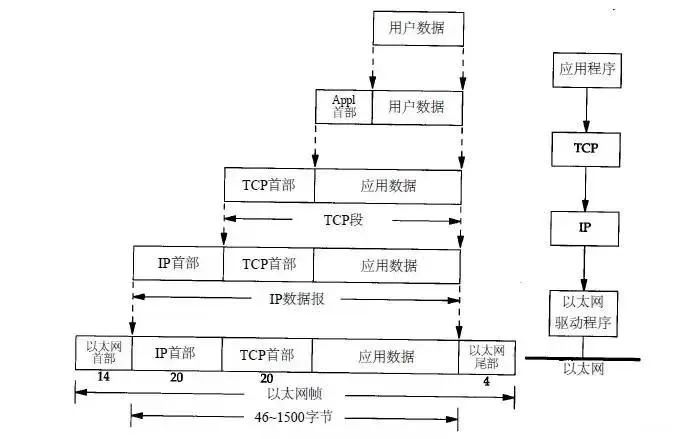
TCP/IP uses encapsulation and multiplexing strategies in packet design. Encapsulation means that during the process of sending data from the application, each layer adds some header information to communicate with the receiving end at the same level. For example, when data is sent from the application to Ethernet, the following diagram shows how data is processed layer by layer:
The application layer is the highest level of the TCP/IP protocol and is the most commonly encountered in mobile development.
Protocols running on TCP:
-
HTTP (Hypertext Transfer Protocol)
Mainly used for regular browsing.
-
HTTPS (Hypertext Transfer Protocol over Secure Socket Layer)
The secure version of the HTTP protocol.
-
FTP (File Transfer Protocol)
As the name suggests, used for file transfer.
-
POP3 (Post Office Protocol, version 3)
Used for receiving emails.
-
SMTP (Simple Mail Transfer Protocol)
-
TELNET (Teletype over the Network)
Logs into the network via a terminal.
-
SSH (Secure Shell, used to replace insecure TELNET)
Used for encrypted secure logins.
Protocols running on UDP:
Used for diskless devices.
-
NTP (Network Time Protocol)
Used for network synchronization.
-
DHCP (Dynamic Host Configuration Protocol)
Dynamically configures IP addresses.
-
DNS (Domain Name Service)
Used for address resolution, email forwarding, etc. (runs on TCP and UDP).
Used for error checking and measuring response time (runs on TCP and UDP).
-
SNMP (Simple Network Management Protocol)
Used for collecting network information and network management.
-
ARP (Address Resolution Protocol)
Used for dynamically resolving Ethernet hardware addresses.
The transport layer provides two ways to reach the target network:
(1) User Datagram Protocol (UDP):
Only provides basic error detection and is a connectionless protocol.
Features: Packages data, limited data size (64k), does not establish a connection, fast speed, but low reliability.
(2) Transmission Control Protocol (TCP):
Provides complete error control and flow control, ensuring normal data transmission, and is a connection-oriented protocol.
Features: Establishes a connection channel, unlimited data size, slower speed, but high reliability. Since the transport layer involves many aspects, such as ports, sockets, etc.
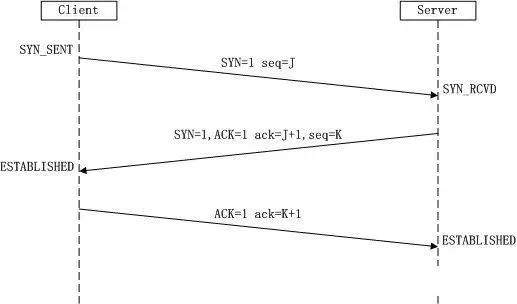
First Handshake:The Client sets the SYN flag to 1, randomly generates a value seq=J, and sends this packet to the Server. The Client enters the SYN_SENT state and waits for Server confirmation.
Second Handshake:After the Server receives the packet, it knows the Client requests to establish a connection from the SYN=1 flag. The Server sets both the SYN and ACK flags to 1, ack=J+1, randomly generates a value seq=K, and sends this packet back to the Client to confirm the connection request. The Server enters the SYN_RCVD state.
Third Handshake:After the Client receives the confirmation, it checks if ack is J+1 and ACK is 1. If correct, it sets the ACK flag to 1, ack=K+1, and sends this packet to the Server. The Server checks if ack is K+1 and ACK is 1. If correct, the connection is successfully established, and both Client and Server enter the ESTABLISHED state, completing the three-way handshake. Data transmission between Client and Server can now begin.
(1):During connection establishment, the Client sends a SYN packet (SYN=i) to the Server and enters the SYN-SEND state, waiting for Server confirmation.
(2):The Server must acknowledge the Client’s SYN (ack=i+1) after receiving the SYN packet, while also sending its own SYN packet (SYN=k), i.e., a SYN+ACK packet. The Server then enters the SYN-RECV state.
(3):The Client receives the Server’s SYN+ACK packet and sends an acknowledgment (ACK) back to the Server (ack=k+1). After sending this packet, both Client and Server enter the ESTABLISHED state, completing the three-way handshake, and begin data transmission.
Since TCP connections are full-duplex, each direction must be closed separately. This principle means that after one party completes its data transmission, it sends a FIN to terminate the connection in that direction. Receiving a FIN only indicates that there is no data flow in that direction, i.e., no more data will be received.
However, data can still be sent on this TCP connection until that direction also sends a FIN. The first party to close will execute an active close, while the other party will execute a passive close, as illustrated in the image above.
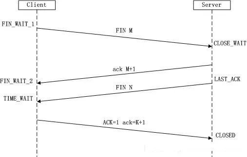
First Wave:The Client sends a FIN to close the data transmission from Client to Server, entering the FIN_WAIT_1 state.
Second Wave:After the Server receives the FIN, it sends an ACK to the Client, acknowledging the sequence number as the received sequence number +1 (similar to SYN, one FIN occupies one sequence number). The Server enters the CLOSE_WAIT state.
Third Wave:The Server sends a FIN to close the data transmission from Server to Client, entering the LAST_ACK state.
Fourth Wave:After the Client receives the FIN, it enters the TIME_WAIT state, then sends an ACK to the Server, acknowledging the sequence number as the received sequence number +1. The Server enters the CLOSED state, completing the four-way handshake.
Why is connection establishment a three-way handshake while connection termination is a four-way handshake?
This is because when the server is in the LISTEN state and receives a SYN packet to establish a connection, it sends both ACK and SYN in one packet back to the Client.
However, during connection termination, receiving a FIN packet from the other party only indicates that the other party will no longer send data but can still receive it, and the local side may not have sent all its data to the other party yet.
Therefore, the local side can either close immediately or send some data to the other party before sending a FIN packet to indicate agreement to close the connection now. Thus, the local ACK and FIN are generally sent separately.
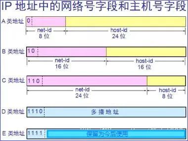
An IP address consists of two parts: the network address and the host address, which have a master-slave relationship:
(1) Network ID, which indicates the network to which the host (or router) is connected. The network address indicates which network it belongs to on the Internet.
(2) Host ID, which indicates the host (or router) itself. The host address indicates which specific host it belongs to within that network.
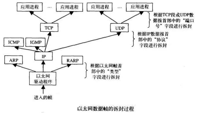
2. Protocol Demultiplexing
Similarly, many application processes use TCP or UDP to transmit data, and therefore need to define an application identifier in the TCP segment or UDP datagram header.
Both TCP and UDP use a 16-bit port number to identify different applications. TCP and UDP store the “source port number” and “destination port number” in the TCP segment header and UDP datagram header, respectively.
The network interface sends and receives data for IP, ARP, and RARP, and similarly, a field must be added to the Ethernet header (assuming the physical network is Ethernet) to indicate which protocol’s data it is.
For this reason, the Ethernet frame header defines a 16-bit “type” field.When the receiving end (also called the destination host) receives an Ethernet frame, the data begins to be transmitted up the protocol stack from the bottom.
Each layer protocol uses the protocol control information carried in the message header to perform corresponding processing, then removes the header from the protocol data unit at each layer and hands the encapsulated data to the upper layer protocol.
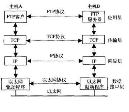
Each layer protocol must check the protocol identifier in the protocol header to determine which protocol should receive the data. This process is called demultiplexing, as shown in the diagram above.
Any two peer layers, such as the transport layer, internet layer, and network interface layer, communicate as if they are directly passing data to each other through horizontal dashed lines, as indicated in the diagram above. This is known as communication between peer layers.
In reality, protocols are the various specifications for transmitting data between two peer layers.
Thus, it can be understood that actual communication occurs in the vertical direction, with encapsulation and demultiplexing operations facilitating physical communication. However, logically, it is peer layer communication occurring in the horizontal direction using protocols.
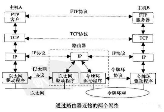
The application layer and transport layer use end-to-end protocols, while there are no these two layers in routers; only end systems have these two layers.
The internet layer is a hop-by-hop protocol, and both end systems and routers have internet layer protocols.
A router has two or more network interfaces, allowing it to connect to two or more networks. One of the purposes of the Internet is to abstract all physical network details in application programs.
In the diagram above, the application layer does not need to care whether an end system is on Ethernet or Token Ring; they communicate through routers.
As different types of physical networks increase, the scale of the Internet continues to grow, necessitating more routers, but the application layer remains the same.
For course inquiries, add: HCIE666CCIE
↑ Or scan the QR code above ↑
If you have any technical points or content you would like to see, please leave a message below!