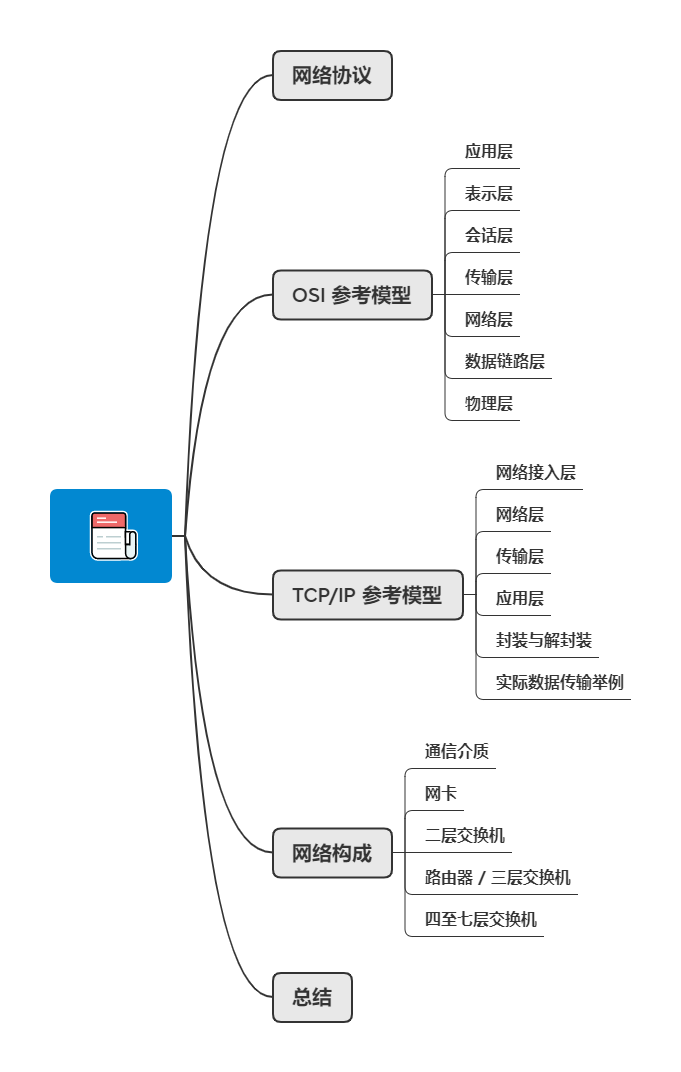
Network Protocols
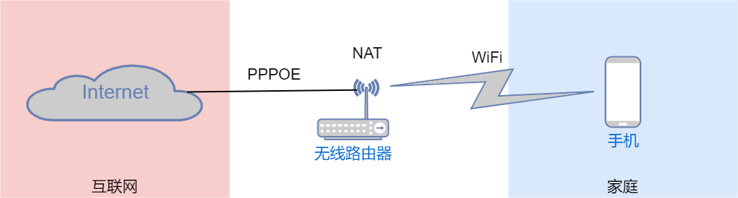
When we connect to the internet using our mobile phones, we utilize many network protocols. Starting from the connection to WiFi, we use the 802.11 (i.e., WLAN) protocol to connect to the network; the phone automatically obtains network configuration using the DHCP protocol, and only after getting the configuration can the phone communicate properly. At this point, the phone is already connected to the local area network and can access devices and resources within the LAN, but cannot use internet applications, such as WeChat, Douyin, etc. To access the internet, relevant protocols need to be implemented on the uplink network devices of the phone, specifically configuring NAT, PPPOE, etc., on the wireless router, and then connecting the local area network to the internet through the internet line provided by the operator, allowing the phone to use WeChat and Douyin.
Local Area Network: A private network within a small area, such as a home network, a company network, or a campus network.
Wide Area Network: A network that connects local area networks in different geographical locations. Operators build wide area networks to achieve interconnection across regions.
Internet: A network that connects the entire world. The internet is an open and interconnected network, not owned by any individual or organization, allowing communication with any host on the internet once connected.
Simply put, devices like phones and wireless routers communicate through various network protocols. Network protocols are standards or rules defined for communication parties to be able to exchange information. As long as devices follow the same network protocol, they can communicate. So who defines these network protocols? ISO has established an international standard called OSI, and the OSI reference model is often used for the formulation of network protocols.
OSI Reference Model
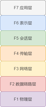
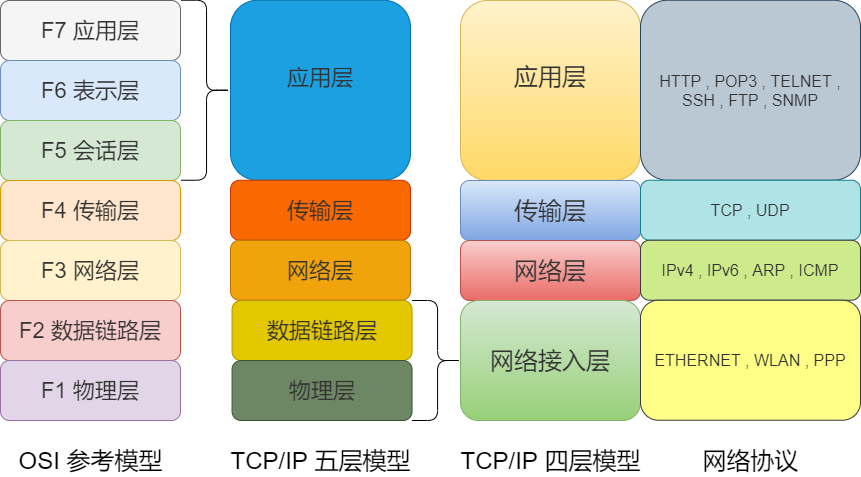
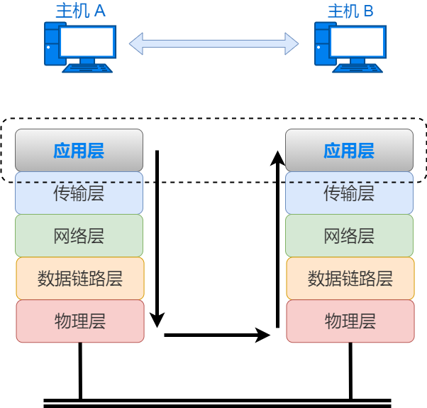
The OSI reference model divides the services provided by network protocols into 7 layers and defines the service content of each layer. The protocols that implement the services of each layer are defined by rules. The layers interact with each other through interfaces, and the same layer interacts through protocols. The OSI reference model only provides a rough definition of the services of each layer and does not define the protocols in detail, but many protocols correspond to a specific layer of the 7-layer model. Therefore, to understand networks, one must first understand the OSI reference model.
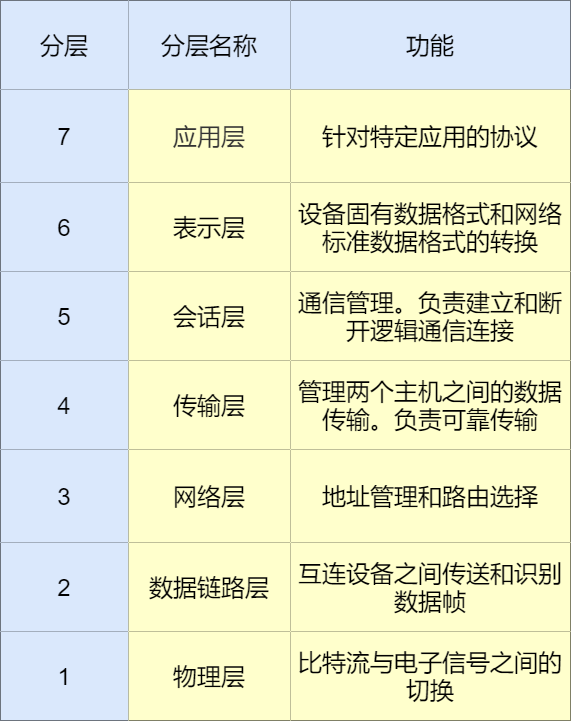
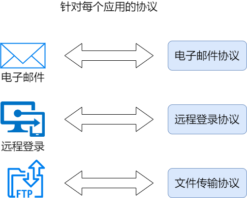
Application Layer
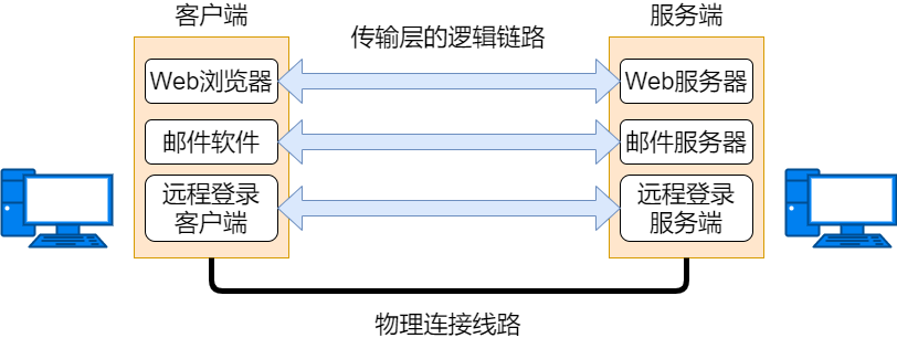
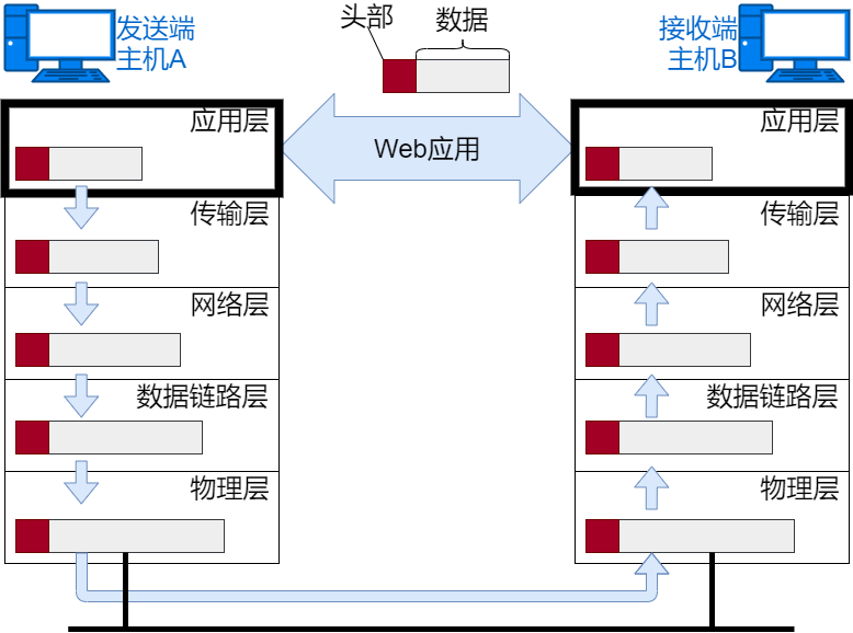
The 7th layer (the top layer) of the OSI reference model. The interface between applications and the network, directly providing services to users. Application layer protocols include email, remote login, and others.
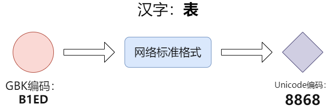
Presentation Layer
The 6th layer of the OSI reference model. Responsible for data format conversion, such as encoding, data format conversion, and encryption/decryption. Ensures that information sent from the application layer of one system can be read by the application layer of another system.
Session Layer
The 5th layer of the OSI reference model. Mainly manages and coordinates communication (dialogue) between various processes on different hosts, responsible for establishing, managing, and terminating sessions between applications.

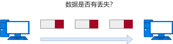
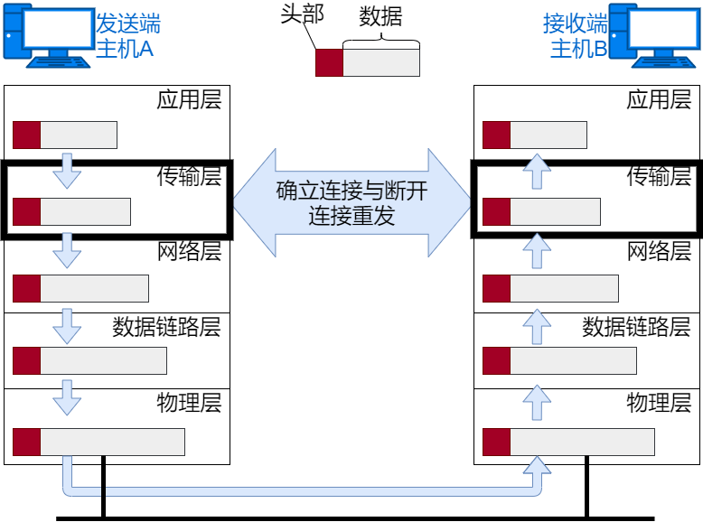
Transport Layer
The 4th layer of the OSI reference model. Provides reliable and transparent data transmission services between communicating hosts, including error control and flow control issues. It only processes on the communicating hosts and does not need to be processed on routers.
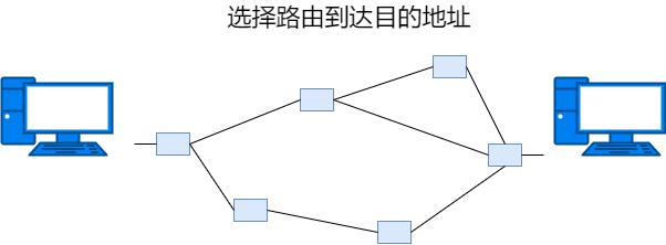
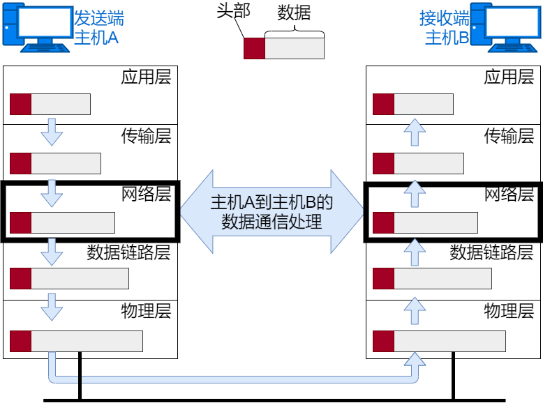
Network Layer
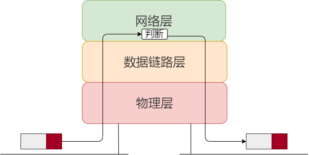
The 3rd layer of the OSI reference model. Responsible for transmitting data to the destination address on the network, mainly responsible for addressing and routing.
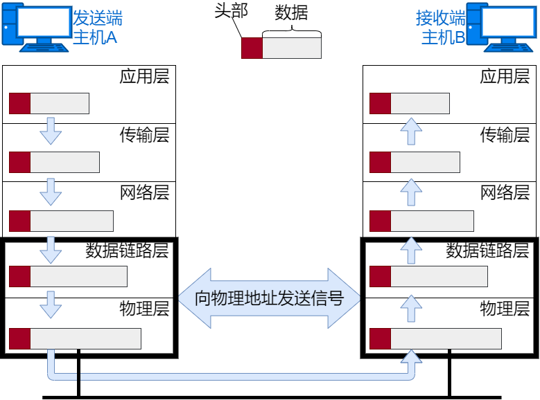
Data Link Layer
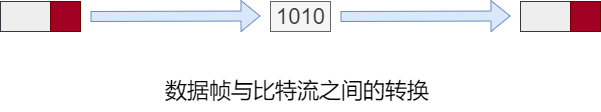
The 2nd layer of the OSI reference model. Responsible for the communication transmission between two interconnected hosts at the physical layer, dividing the bit stream composed of 0s and 1s into data frames for transmission to the other end, i.e., the generation and reception of data frames. Communication transmission is actually realized through physical transmission media. The data link layer’s role is to process data between these interconnected devices through transmission media.
The network layer and data link layer both send data to the receiving end based on the destination address, but the network layer is responsible for sending the entire data to the final destination address, while the data link layer only sends data within a segment.
Physical Layer
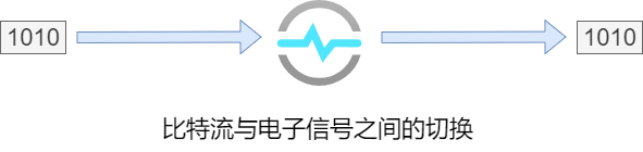
The 1st layer (the lowest layer) of the OSI reference model. Responsible for the mutual conversion between logical signals (bit streams) and physical signals (electrical signals, optical signals), providing physical connections for the data link layer through transmission media.
TCP/IP Reference Model
Since the OSI reference model divides services too finely, defining the reference model before defining protocols is somewhat idealistic. The TCP/IP model, on the other hand, is a model summarized from existing protocols, becoming the practical network protocol standard in the industry.
TCP/IP is a protocol suite suggested and promoted by the IETF, which includes protocols like IP, TCP, HTTP, etc. TCP/IP was developed for use on the internet, so the internet’s protocols are TCP/IP.
First, let’s introduce the correspondence between TCP/IP and the OSI layers, as well as the main protocols of each layer of TCP/IP.
Network Access Layer
The TCP/IP model does not define the functions of the physical and data link layers based on the premise that they are transparent, so we can merge the physical and data link layers into the network access layer. The network access layer manages the network medium and defines how to use the network to transmit data. However, during communication, these two layers play different roles, so they may also be referred to as hardware and network interface layer. TCP/IP can be divided into four or five layers, as long as the principles are understood.
Devices are interconnected through physical transmission media, and the data transmission between interconnected devices uses MAC addresses to identify the devices connected to the same transmission medium.
Network Layer
Equivalent to the 3rd layer of the OSI model, using the IP protocol. The IP protocol forwards packet data based on IP addresses, sending data packets from the source address to the destination address.
The functions of the network layer and transport layer in the TCP/IP model are usually provided by the operating system. Routers achieve the function of forwarding data packets through the network layer.
During network transmission, each node will determine which network card to send the message based on the address information of the data. Each address will refer to a list of outgoing interfaces, and the table referred to in MAC addressing is called the MAC address table, while the table referred to in IP addressing is called the routing table. The MAC address table is generated automatically through self-learning, while the routing table is generated automatically based on routing protocols. The MAC address table records the actual MAC addresses, while the routing table records the network number (the network number and subnet mask).
-
IP
IP is a protocol for transmitting data packets across networks, using IP addresses as host identifiers, allowing the entire internet to receive data. The IP protocol is independent of the underlying medium, enabling data forwarding from the source to the destination. The IP protocol does not have a retransmission mechanism and is considered an unreliable transmission protocol.
-
ICMP
Used to transmit control messages between IP hosts and routers to diagnose network health.
-
ARP
A protocol that resolves MAC addresses from the IP addresses of data packets.
Transport Layer
Equivalent to the 4th layer of the OSI model, the main function is to enable communication between applications, identifying applications through port numbers. The protocols used include connection-oriented TCP protocol and connectionless UDP protocol.
Connection-oriented means establishing a logical communication link between the sending and receiving hosts before sending data. It is like making a phone call; after dialing the other party’s phone number, you can only have a conversation after the other party answers the call, and when the call ends, it is like cutting off the power.
Connectionless means that there is no requirement to establish and disconnect connections. The sender can freely send data at any time. It is like sending a letter; there is no need to confirm whether the recipient’s information is real or whether the recipient can receive the letter, as long as there is a mailing address.
-
TCP
TCP is a connection-oriented transport layer protocol that can control the connections it provides. It is suitable for applications that require reliable transmission, such as file transfers.
-
UDP
UDP is a connectionless transport layer protocol that does not control the connections it provides. It is suitable for real-time applications, such as IP telephony, video conferencing, live broadcasts, etc.
Application Layer
Equivalent to the combined 5th to 7th layers of the OSI model, it not only implements the functions of the OSI model application layer but also the functions of the session and presentation layers. Protocols like HTTP, POP3, TELNET, SSH, FTP, and SNMP are application layer protocols.
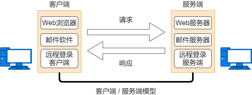
Most TCP/IP applications belong to the client/server model. The program providing the service is called the server, while the program receiving the service is called the client. The client can send requests to the server at any time.
-
HTTP
is the application layer communication protocol between WWW browsers and servers, with the main data format being HTML. HTTP defines high-level commands or methods for browsers to communicate with web servers.
-
POP3
Simple Mail Transfer Protocol, used between email clients and email servers.
-
TELNET and SSH
Remote terminal protocols used for remote management of network devices. TELNET transmits in plaintext, while SSH transmits encrypted data.
-
SNMP
Simple Network Management Protocol, used for network management software to monitor and manage network devices.
Encapsulation and Decapsulation
Typically, the information provided for protocols includes a header, and the content to be sent is the data. In each layer, a header is added to the data being sent, which contains necessary information for that layer, such as the target address and protocol-related information. From the perspective of the next layer, all packets received from the previous layer are considered data for that layer.
Before data is sent, according to the reference model from top to bottom, protocol packet header information is added as the data passes through each layer; this process is called encapsulation.

After data is received, according to the reference model from bottom to top, protocol header information is removed as the data passes through each layer; this process is called decapsulation.
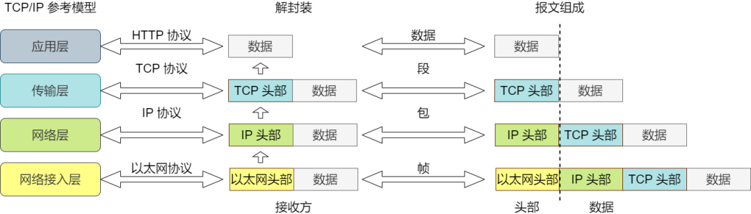
Data encapsulated by the transport layer protocol is called a segment, data encapsulated by the network layer protocol is called a packet, data encapsulated by the data link layer protocol is called a frame, and data transmitted at the physical layer is called bit.
In TCP/IP communication, MAC addresses, IP addresses, and port numbers are used as address identifiers. Even at the application layer, an email address can be used as a network communication address.
Example of Actual Data Transmission
In real life, the internet uses the TCP/IP protocol for network connections. Let’s take accessing a website as an example to see how communication occurs over the network.
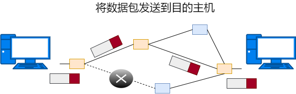
Sending Data Packets
When accessing an HTTP website, you open your browser, enter the URL, and hit enter to start the TCP/IP communication.
Application Processing
First, the application program will perform HTML format encoding processing, corresponding to the presentation layer function of OSI. After encoding, the data may not be sent immediately, corresponding to the session layer function. At the moment the request is sent, a TCP connection is established, and then data is sent on the TCP connection. The next step is to send the data to the next layer, TCP, for processing.
TCP Module Processing
TCP will successfully send the data received from the application layer to the destination. To achieve reliable transmission, TCP encapsulates the data with TCP header information. The TCP header information includes the source and destination port numbers (to identify applications on the host), sequence numbers (to confirm which part is data), and checksums (to determine if the data is corrupted). Then, the segment encapsulated with TCP header information is sent to IP.
IP Module Processing
IP treats the data segment passed from TCP as its own data and encapsulates it with IP header information. The IP header information includes the destination and source IP addresses, as well as the upper layer protocol type information.
After generating the IP packet, it is sent based on the host’s routing table.
Network Interface Processing
The network interface encapsulates the incoming IP packet with Ethernet header information and processes it for sending. The Ethernet header information includes the destination MAC address, source MAC address, and upper layer protocol type information. The Ethernet data frame is then transmitted to the receiving end through the physical layer. The FCS in the sending process is calculated by hardware and added to the end of the packet. The purpose of setting FCS is to determine whether the data packet has been corrupted due to noise.
Receiving Data Packets
The packet receiving process is the reverse of the sending process.
Network Interface Processing
After receiving the Ethernet packet, it first checks whether the destination MAC address in the header information is for itself. If not, the packet is discarded. If it is for itself, it checks whether the upper layer protocol type is an IP packet, and the Ethernet frame is decapsulated into an IP packet, which is then sent to the IP module for processing. If the protocol type is unrecognized, the data is discarded.

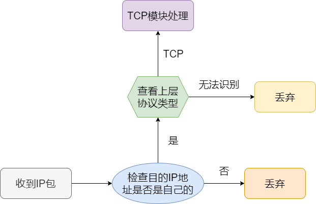
IP Module Processing
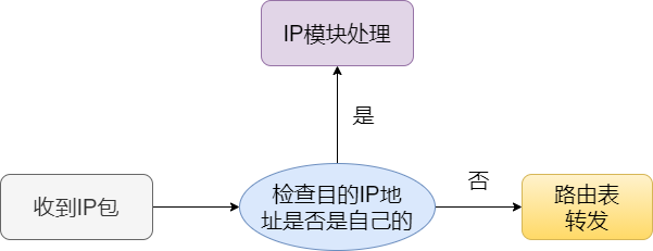
After receiving the IP packet, similar processing is performed. It checks whether the destination IP address in the header information is for itself. If it is for itself, it checks the upper layer protocol type. If the upper layer protocol is TCP, the IP packet is decapsulated and sent to the TCP protocol for processing.
If there is a router and the receiving end is not its own address, the data is forwarded based on the routing control table.
TCP Module Processing
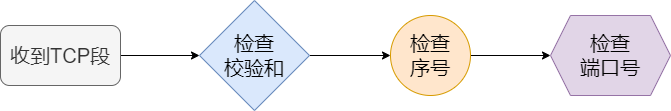
After receiving the TCP segment, it first checks the checksum to determine if the data is corrupted. Then it checks whether the data is received in the correct order based on the sequence number. Finally, it checks the port number to identify the specific application.
Once the data is completely received, an “acknowledgment receipt” is sent back to the sender. If this acknowledgment does not reach the sender, the sender will think that the receiver did not receive the data and will keep resending it.
Once the data is fully received, the TCP segment is decapsulated and sent to the application program identified by the port number.
Application Processing
The application program receives the data, and through parsing the content of the data, it learns about the webpage content requested by the sender, then follows the HTTP protocol for subsequent data interaction.
Network Composition
Building a network involves various cables and network devices. Below are some common hardware devices. The layer numbers referred to for hardware devices are based on the OSI reference model, not the TCP/IP model.

Communication Media and Data Link
Devices are connected through cables. Wired cables include twisted pair cables, fiber optics, serial cables, etc. Choose the corresponding cable based on the data link. Transmission media can also be divided into different types of electromagnetic waves, such as radio waves and microwaves.
Transmission Rate: Measured in bps, it refers to the amount of data transmitted in a unit of time. Also known as bandwidth, the larger the bandwidth, the stronger the network transmission capacity.
Throughput: Measured in bps, it refers to the actual transmission rate between hosts. The term throughput not only measures bandwidth but also considers the CPU processing capacity of the hosts, the degree of network congestion, the share of data fields in the packets, and other information.
Network Interface Card
Any host connecting to the network must use a network interface card. It can be a wired network card for connecting to wired networks or a wireless network card for connecting to WiFi networks. Each network card has a unique MAC address, also known as the hardware address or physical address.

Layer 2 Switch
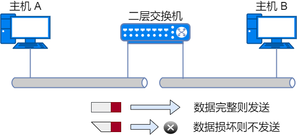
Layer 2 switches operate at the 2nd layer (data link layer) of the OSI model. They can recognize data frames in the data link layer and forward frames to another data link.
There is a data bit in the data frame called FCS, which is used to verify whether the data is correctly delivered to the destination. Layer 2 switches discard corrupted data by checking this value.
Layer 2 switches determine whether to forward data frames based on the self-learning mechanism of MAC addresses.
Router / Layer 3 Switch
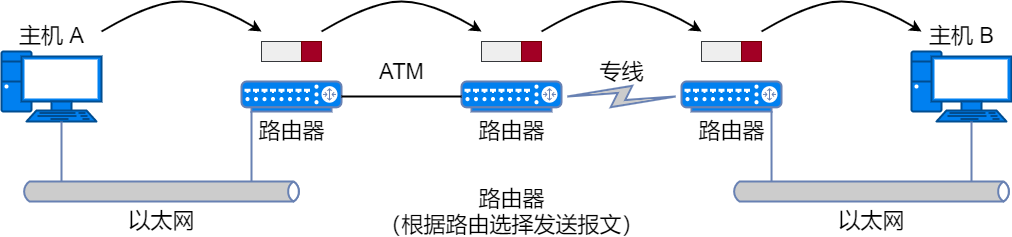
Routers operate at the 3rd layer (network layer) of the OSI model, connecting two networks and forwarding packets. While Layer 2 switches process based on MAC addresses, routers / Layer 3 switches process based on IP addresses. Therefore, the address at the network layer in TCP/IP becomes the IP address.
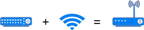
Routers can connect different data links, such as connecting two Ethernet networks or connecting an Ethernet network with a wireless network. Common household wireless routers are also a type of router.
Layer 4 to 7 Switches
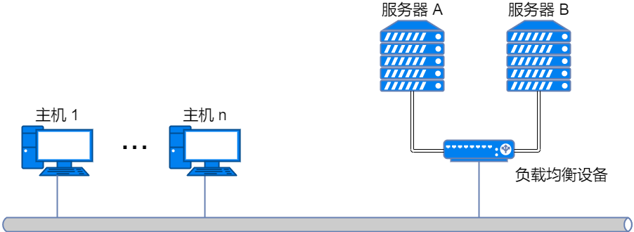
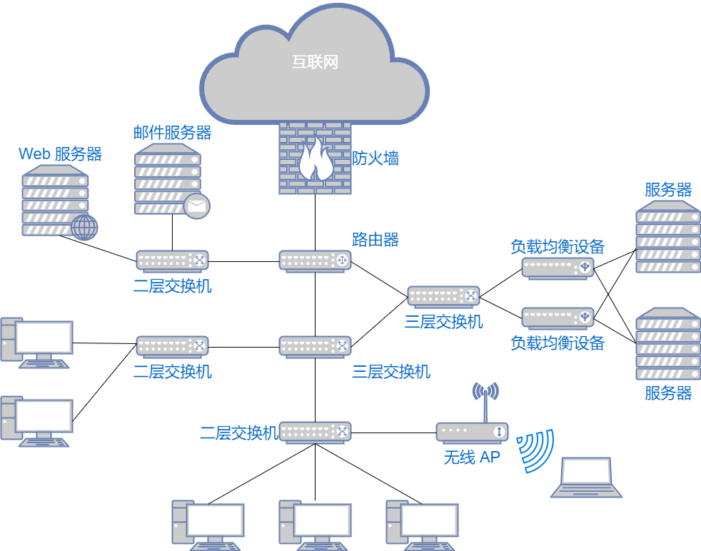
Layer 4 to 7 switches are responsible for processing data from the transport layer to the application layer in the OSI model. Based on transport layer protocols like TCP and the application layer above, they analyze the data being sent and received and perform specific processing. For example, if a single server for a video website cannot meet access demands, a load balancing device distributes the access load to multiple backend servers, which is one application of Layer 4 to 7 switches. There are also bandwidth control, wide area network accelerators, firewalls, and other application scenarios.
Conclusion
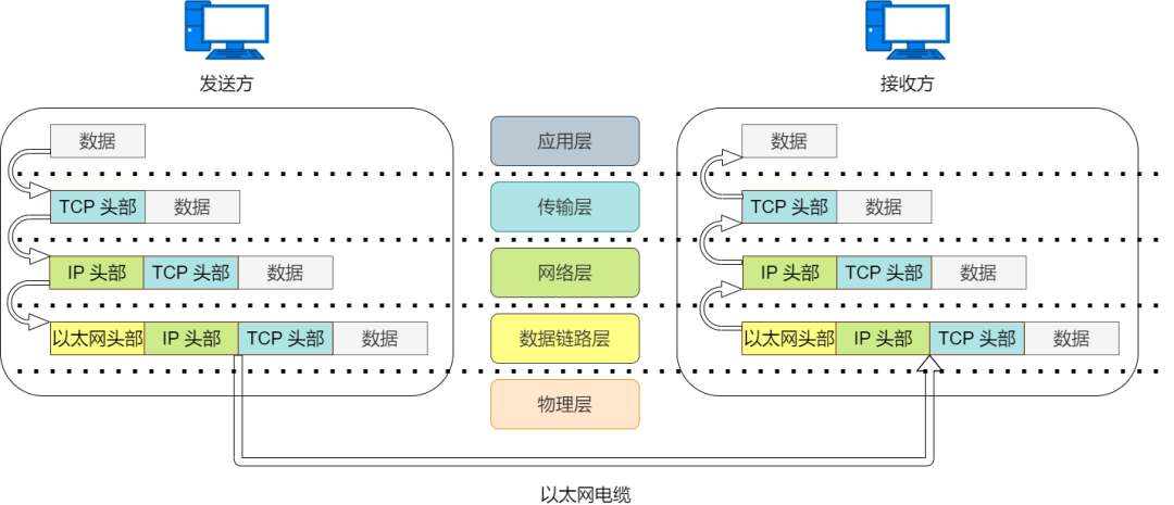
Application layer devices include computers, mobile phones, servers, etc. Application layer devices do not forward data; they are sources or destinations of data and possess functions below the application layer. When sending data, the data is encapsulated layer by layer in a top-down order and sent out through Ethernet. When receiving data, the data is decapsulated layer by layer in a bottom-up order, ultimately restoring the original data.
Data link layer devices include Layer 2 switches, bridges, etc. Layer 2 network devices only forward data, forwarding based on the recognition of MAC addresses. After receiving data, Layer 2 switches view the Ethernet header information of the outermost layer of the data, see the destination MAC address, and send the data frame out from the corresponding port. Switches do not decapsulate the data frame; they only need to know the MAC address information to forward the data correctly.
Network layer devices include routers, Layer 3 switches, etc. Layer 3 network devices only forward data, forwarding based on the recognition of IP addresses. After receiving data, routers first check the Ethernet header information of the outermost layer, and when the destination MAC address is theirs, they decapsulate the Ethernet header and check the data’s IP address. When making forwarding decisions based on the IP routing table, the router uses the MAC address of the next-hop device as the destination MAC address in the Ethernet header, then re-encapsulates the Ethernet header and forwards the data.
The network devices that forward data and the data at the application layer are like a courier and a package. The courier delivers the package according to the destination address without needing to understand the specific content inside the package.
Using layered functions to distinguish network devices is no longer applicable. Switches integrating Layer 3 routing functions are Layer 3 switches, and wireless APs integrating router functions are wireless routers. However, for convenience of explanation, it is usually better to describe the functions and principles of individual devices.
References:
Illustrated TCP/IP – Takashi Takeshita
Basic Networking – Tian Guo