1. Input Circuit Wiring
The input circuit is the port through which the PLC receives signals (for analog signals, typically 0-40mA DC current or 0-10V DC voltage signals). Input wiring refers to the external input devices (any passive contacts and NPN transistors with open collector) that connect to the input circuit, closing the circuit and illuminating the input indicator LED. Common external input devices include buttons, proximity switches, toggle switches, dip switches, and various sensors, which serve as the main control devices for the system.
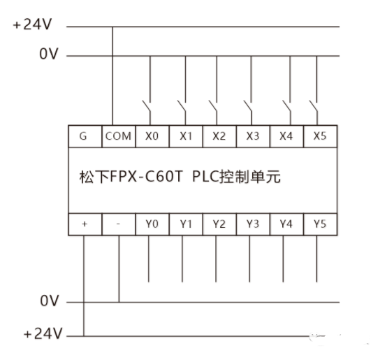
(1) Connection of PLC Input Module to Main Control Devices
The Panasonic PLC in the diagram uses a DC common point input, so the input points share a common terminal COM, which also carries a DC24V power supply. When writing programs, it is important to note whether the external devices use normally closed or normally open contacts.
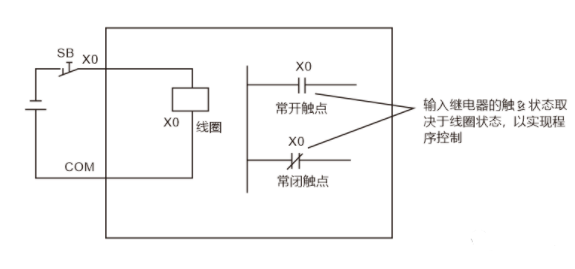
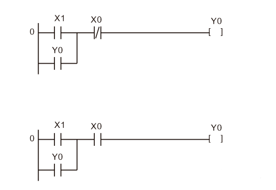
In the electrical schematic of the input side, the stop button SB0 uses a normally closed contact, wired in series with the control line for stop control. The start button SB1 uses a normally open contact. The two ladder diagrams designed achieve the same control function, but the stop signal X0 uses different types of contacts, thus the external stop button connected at the endpoint will also have a different contact type.
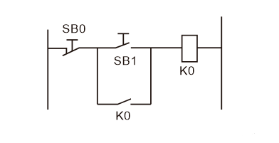
The I/O allocation is SB0-X0, SB1-X1, output K0-Y0. When using normally closed contacts externally, if the button is not operated, the output Y0 remains normally connected. In PLC control systems, external switches for starting or stopping are generally selected as normally open types.
(2) Connection of Proximity Switch to PLC Input Module
In the design of PLC control systems, wiring work is relatively minor, but it is the foundation of programming design. To ensure the correctness of wiring, a clear understanding of the PLC’s input and output circuits is necessary.
1. PLC DC input circuit: There are active (common anode) input circuits and sinking (common cathode) input circuits. In a sinking input circuit, the COM terminal of the PLC is connected to the positive terminal of the external DC power supply. For example, the COM terminal of the Siemens S7-400 PLC DC input module must be connected to the positive terminal of the external power supply. Therefore, the input signal for Siemens PLC is a low voltage signal; if the external signal is a high voltage signal, it should be converted through an intermediate relay.
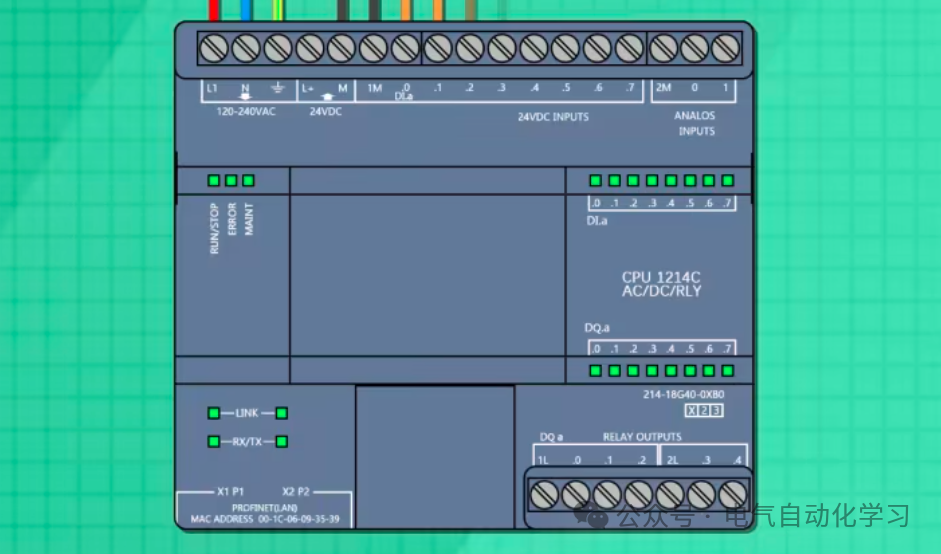
2. The voltage of the PLC AC input circuit is generally AC120V or AC230V, which goes through resistance limiting and capacitor isolation before being rectified into DC. Therefore, the input signal delay time is longer than that of the DC circuit, but the input side is high voltage, ensuring the reliability of the input signal, which is generally used in harsh environments where response requirements are not high.
(3) Connection of Digital Signal to PLC Input Module
For different PLC input circuits, the input method of sensors (NPN or PNP) should be correctly selected. When an NPN type sensor is activated, the OUT terminal is at 0V (the NPN output terminal OUT should be connected to the PLC’s sinking input). It outputs a low-level signal. When a PNP type sensor is activated, the OUT terminal is at +V, outputting a high-level signal.
(4) Optimization of PLC Input Circuit Wiring
1. Reduce the number of input points and group inputs.
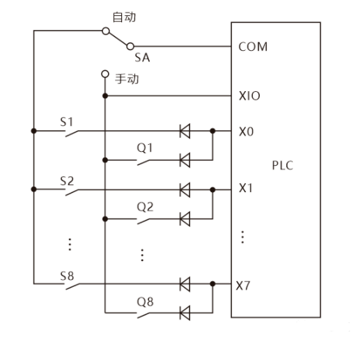
As shown in the diagram, the system is divided into automatic and manual working modes. Q1-Q8 are the input signals used in manual mode, while S1-S8 are the input signals used in automatic mode. S1 and Q1 share the input point X0, so when the PLC is running, only one group of signals will be used, allowing for shared PLC input points. (The diodes in the diagram are used to prevent parasitic circuits and avoid erroneous input signals.)
2. Multifunctionality of input devices: In the PLC system, the PLC logic functions can be utilized to enable a device to generate different signal actions under different conditions.
3. Connection of different forms of DC input signals to PLC.
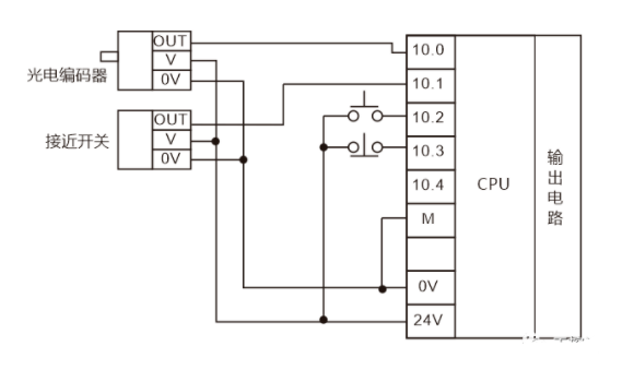
DC active input signals are generally 24V. When mixed with other passive switch signals connected to the PLC input points, the 0V point of the voltage must be connected. In the above diagram, input points I0.0 and I0.1 are connected to the output OUT signals of photoelectric encoders and proximity switches, with their driving power supplied by the PLC’s own 24V voltage.
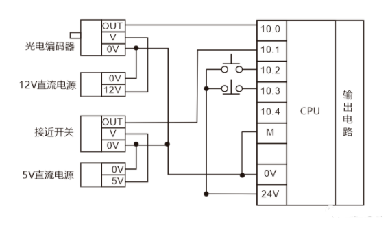
When connecting different voltage DC signals to the PLC input module input points, ensure that the reference points for the signal potential differences are the same, meaning their 0V signals must be connected together.
4. For switch signals introduced to the PLC via long wires, small relays can be used to transfer input signals, avoiding interference from external strong electromagnetic fields.
2. Output Circuit Wiring
Since PLC output components are encapsulated on the circuit board and connected to the output terminal board, short-circuiting the output components can damage the printed circuit board, so fuses should be used to protect the output components. The switch output modules include relays, transistors, and thyristor outputs. Output wiring is divided into common output and independent output. DC output requires a flyback diode for protection, AC output requires an RC snubber circuit, and transistor and thyristor outputs require bypass resistors for protection, as well as external emergency stop circuits.
(1) There are three types of PLC outputs, and wiring for these three output circuits should be noted.
1. Relay output wiring: Applicable to both AC and DC circuits, different common points can carry different AC and DC voltage loads. Load capacity is differentiated by load nature: resistive load 2A/1 point, 8A/4 points COM, inductive load capacity 80VA, bulb load 100W. It can be seen that relay-type output PLCs can handle relatively large currents, but the response time of the output contacts is relatively slow.
2. Transistor output: Applicable to DC circuits, voltage range DC5-30V, resistive load 0.5A/1 point, 0.8A/4 points COM, inductive load capacity 12W/DC24, bulb load 1.5W/DC24. It can be seen that transistor-type output PLCs have a fast response time for output contacts, but the current they can handle is small.
3. Thyristor output: Suitable for high-frequency operation, but can only handle DC5-30V, with a maximum load current of 0.5A and a bulb load of 30W.
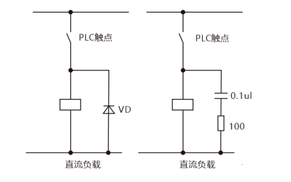
4. An appropriate fuse must be set in the output circuit for protection. For DC inductive loads, a diode should be connected in parallel to extend the contact life, with the diode rated for 5-10 times the load voltage and greater than the load current.
5. Neon lamps or small current loads require a surge suppressor in parallel.
6. For motor forward and reverse circuits, in addition to the PLC internal program needing to design interlocks, the external wiring must also be interlocked.
(2) Selection of COM Points
Since there are no fuses inside the PLC, a fuse should be added at the COM point. When there are many types of loads and high currents, a PLC product with one COM point can drive 1-2 output points. When there are many loads but fewer types, a PLC product with one COM point can drive 4-8 output points.
(3) Connection of PLC to Inductive Devices
When the PLC input and output terminals are connected to inductive load components, DC output requires a flyback diode protection (a flyback diode connected in parallel across the DC circuit), and AC output requires an RC snubber circuit.
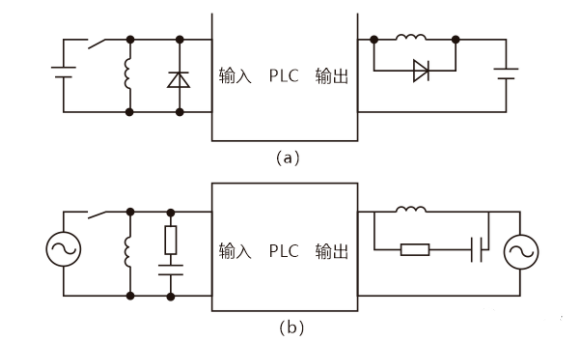
For high-capacity load circuits, an RC snubber circuit must be connected across the main contacts of the relay.
(4) Connection of PLC to Seven-Segment LED Display
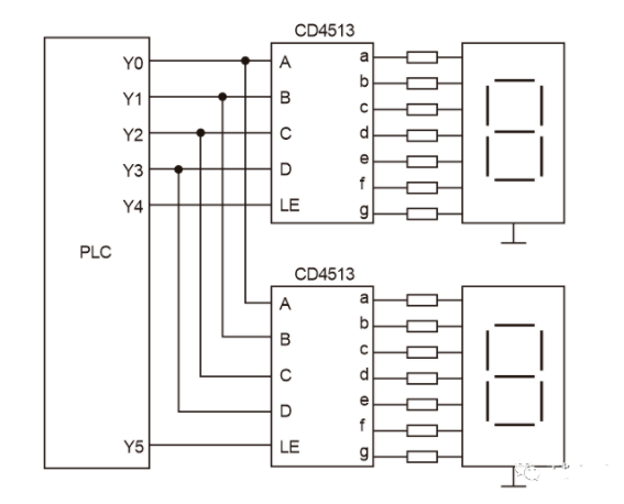
In the above diagram, the data input terminals A-D of two CD4513s share four output terminals Y0-Y3 of the PLC, with A being the lowest and D the highest. LE is the latch input terminal; when LE is high, the input data will be stored in the chip’s register and displayed after decoding. When using a relay output module with the PLC, a pull-down resistor should be connected to each output terminal connected to the CD4513 to avoid floating inputs when the output relay is disconnected.
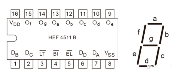
Seven-segment displays come in common cathode (common terminal grounded) and common anode (common terminal connected to +5V) types, which are commonly used display devices in electrical instruments.
(5) Optimization of PLC Control System Output Circuit Wiring
Measures to reduce output points.
1. Massive output: To activate a specific device (load), simply control the corresponding output relay. When using massive output, loads that are activated simultaneously must be arranged in the same column.
2. Group output: Each PLC output point can control two loads that do not operate simultaneously. When two groups of loads will not operate at the same time, they can be switched using an external switch SA.
3. Parallel output: Two identical loads can be connected in parallel to share one PLC output point.
4. Measures to improve PLC output reliability: The relay contact capacity of PLC output modules is generally 2A. If the load power at the output point is too high, an output relay can be used to drive an intermediate relay, which in turn drives the load.
Disclaimer: This article is reprinted from the internet, and the copyright belongs to the original author. If there are any copyright issues, please contact us for deletion. Thank you!