Hello everyone, I am the blue fish tail, and this is Fish World Talk.
Recently, I have been reading the book “Authoritative Guide to ARM Cortex-M0” translated by Wu Changyu and Wei Jun, and I want to have a more systematic understanding of the MCU at the core level. Because my usual work mostly stays at the upper-level function debugging or verification, I actually do not have a deep understanding of the underlying logic. Therefore, I am writing this series of short articles to record my insights from the reading.
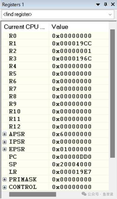
Inside the Cortex-M0 core, there are multiple system/core-level registers, as shown in the figure below:

Among them, R0-R12 can all be considered general-purpose registers, which can be used as carriers for storing data in various assembly instructions.
In addition, there are several registers with special meanings.
1. R13/SP
R13/SP is the stack pointer, used for accessing the stack space during PUSH and POP instructions in assembly, that is, push and pop operations. The SP can be divided into MSP (Main Stack Pointer) and PSP (Process Stack Pointer), generally using MSP by default after power-on, and PSP will be used only in systems with an OS (Operating System).
2. R14/LR
R14/LR is the link register, which stores the return address of a subroutine or function call, meaning that after executing the subroutine or completing the function call, the address in LR will be loaded into the PC register, waiting for the next execution. Therefore, the value in LR is generally the address of the next line of code after the subroutine or function call.
3. R15/PC
R15/PC is called the program counter, and its value can be simply understood as the address value of the currently executing instruction +4, so it points to the instruction that is about to be executed.
4. xPSR (APSR/IPSR/EPSR)
xPSR is a composite program status register, where APSR is the application program status register, generally used for controlling program jumps. Currently, I use it relatively less in embedded development;
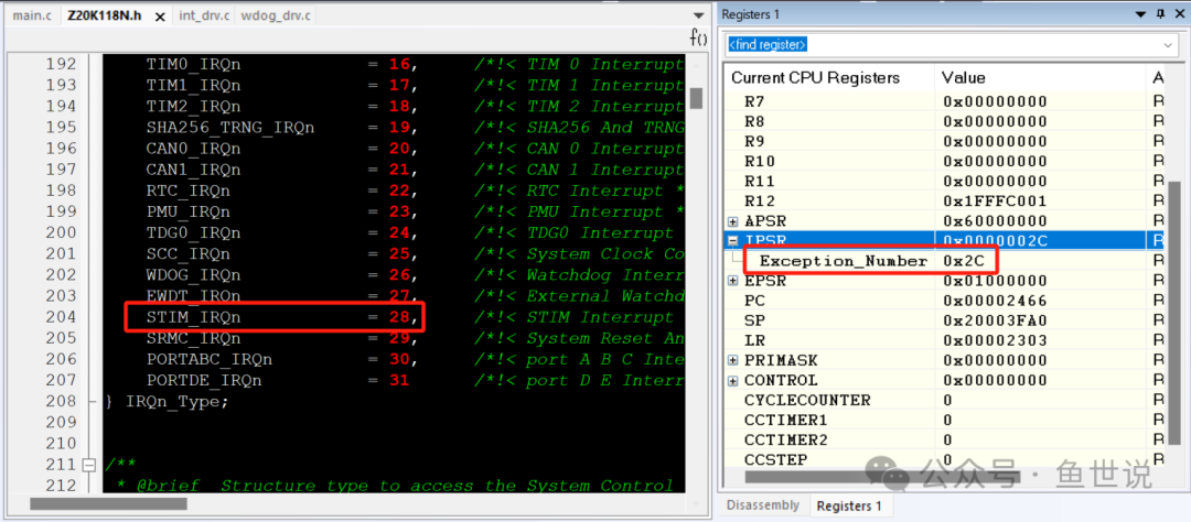
IPSR is the interrupt program status register. Since each type of exception interrupt in Cortex-M0 has a specific number, IPSR can directly indicate which exception interrupt service is currently being executed. For example, in the figure below, the STIM interrupt request source number is 0d28, and the interrupt service number starts from 0d16, so the actual exception service number displayed in IPSR is 0d28 + 0d16 = 0x2c. Therefore, this register is very convenient and effective for checking the currently executing interrupt service;

EPSR is the execution program status register, indicating whether the core is currently in Thumb state. Since Cortex-M0 only supports Thumb state, the T bit of EPSR must be 1. Clearing this bit and executing an instruction will cause a hardware exception interrupt.
xPSR register can be accessed as a single register, as shown in the figure below:

5. PRIMASK
PRIMASK has only one configurable bit width, used as an interrupt mask register. You can use assembly MSR/MRS or CPS instructions to set the value of this register, which can mask all interrupts except NMI (non-maskable interrupt) and hardware error interrupts. This is very useful in situations where timing is critical.

6. CONTROL
CONTROL register is mainly used to select the two stack pointers mentioned above. After system reset, MSP is used as the stack pointer by default. Of course, you can also set the first bit of the CONTROL register to 1 to choose to use PSP, but generally there is no need or necessity for this.

Alright, that’s it for today’s discussion on Cortex-M0 system registers. Thank you all!