
The reset boot process of the ARM Cortex-M core is also known as the reset sequence. Below is a brief summary and analysis of this process.
The reset boot process of the ARM Cortex-M core is different from most other CPUs and also differs from previous ARM architectures (such as ARM920T, ARM7TDMI, etc.). Most CPUs start running from the first instruction obtained at 0x0000_0000 after a reset, however, this is not the case for the ARM Cortex-M core. Its reset sequence is:
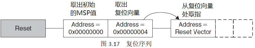
1. Get the initial value of
MSPfrom address0x0000_0000;2. Get the initial value of
PCfrom address0x0000_0004, and then fetch the instruction from the address corresponding to this value.
As shown in the figure below:
In fact, the default interrupt vector table starts at address 0x0000_0004 (some materials consider the initial value of the MSP pointer at address 0x0000_0000 as part of the interrupt vector table, which seems inappropriate). The layout of the interrupt vector table for the ARM Cortex-M core is shown in the figure below:
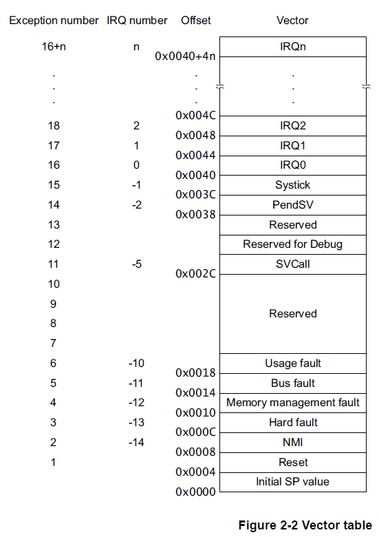
Note: The location of the interrupt vector table can be changed; this is the default setting.
It is worth noting that in the ARM Cortex-M core, after an exception occurs, it does not execute the code at the corresponding position in the interrupt vector table, but instead stores the data at that position into PC, and then fetches the instruction from that address. In short, the interrupt vector table of the ARM Cortex-M should not contain jump instructions, but should contain the entry addresses of ISR programs.
With the above analysis, it is easy to understand the reset sequence. The reset is actually equivalent to an occurrence of a Reset exception, and as can be seen from the figure, the data stored at address 0x0000_0004 is exactly the entry address of the interrupt handler corresponding to the Reset exception.
Additionally, there are two detailed issues that need to be noted:
<span>1. </span><span>0x0000_0000</span>stores the initial value ofMSP, and the lowest three bits must be 0;2.
0x0000_0004must store an address whose lowest bit must be 1.
The first issue is due to the ARM AAPCS convention for stack usage:
5.2.1.1 Universal stack constraints At all times the following basic constraints must hold: Stack-limit < SP <= stack-base. The stack pointer must lie within the extent of the stack. SP mod 4 = 0. The stack must at all times be aligned to a word boundary. 5.2.1.2 Stack constraints at a public interface The stack must also conform to the following constraint at a public interface: SP mod 8 = 0. The stack must be double-word aligned.
In short, the convention stipulates that the stack must always be 4-byte aligned, and must be 8-byte aligned at the entry point, and the lowest two bits of SP are set to 0 at the hardware level.
The second issue relates to the ARM and Thumb modes. In ARM, the address in PC must be 32-bit aligned, and its lowest two bits are also set to 0 at the hardware level, thus the lowest two bits of the data written to PC do not represent the actual addressing address. The lowest bit is used in ARM to determine whether the instruction is an ARM instruction or a Thumb instruction; if the lowest bit is 0, it represents an ARM instruction; if the lowest bit is 1, it represents a Thumb instruction. In the Cortex-M core, ARM mode is not supported, and forcing a switch to ARM mode will trigger a Hard Fault.
Finally, let’s write a small program to validate the above analysis. This program is based on the STM32F4 series microcontroller, and its purpose is to set the PA0 pin to high. This should also be the most concise way to achieve this goal.
rAHB1ENR        EQU     0x40023830
AHB1ENRValue    EQU     0x00000001

rMODER          EQU     0x40020000
MODERValue      EQU     0xA8000001

rODR            EQU     0x40020014
ODRVaule        EQU     0x00000001

    AREA RESET, DATA, READONLY
    DCD 0x00000400
    DCD Start

    AREA |.text|, CODE, READONLY
    ENTRY

Start
    LDR R0, =rAHB1ENR
    LDR R1, =AHB1ENRValue
    STR R1, [R0]

    LDR R0, =rMODER
    LDR R1, =MODERValue
    STR R1, [R0]

    LDR R0, =rODR
    LDR R1, =ODRVaule
    STR R1, [R0]

    B .
    END
Line 11 uses the DCD pseudo-instruction to allocate 4 bytes of storage space and sets its value to 0x0000_0400; line 12 similarly places the address of the Start label at an offset of 4 bytes; line 17 and the following part after the Start label is the main part of the program, which sequentially completes the steps of enabling the RCC clock for GPIOA, setting PA0 to output mode, and setting PA0 high.
During linking, the RESET section will be placed at the beginning of the target file, thus the data at address 0x0000_0000 is equivalent to 0x0000_0400, and the data at address 0x0000_0004 is the entry address of the Start part.
However, it should be noted that in the STM32F4 chip, the internal Flash address starts from 0x0800_0000, and when the BOOT pin is set to Flash boot, the chip will automatically map the area 0x0000_0000 0x000F_FFFF to 0x0800_0000 0x080F_FFFF, at which point they can be regarded as equivalent.
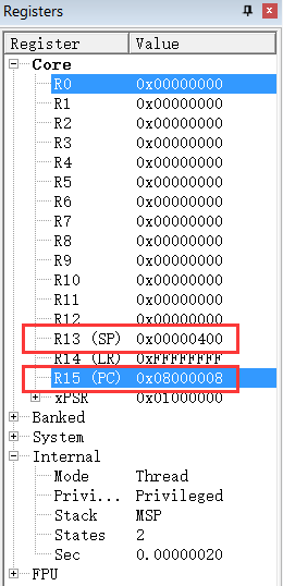
Using Debug mode for debugging, the values of the CPU registers after reset are as follows:
The data in Flash is shown in the figure:
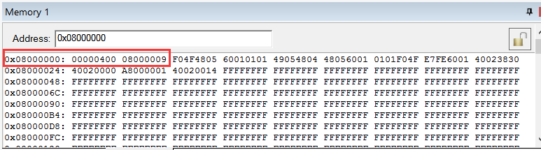
It can be seen that the compiler intelligently sets the data at 0x0800_0004 to 0x0800_0009, rather than the real address value of the Start label, which indicates that this is a Thumb-2 instruction. After reset, the value in PC is 0x0800_0008, and the value in SP is 0x0000_0400, which completely matches the expected result.
Finally, it is worth mentioning that the above simple program has a problem: the program in the Start part actually occupies the space of the interrupt vector table, which is not an issue when no exceptions occur, but once an exception occurs, the program execution will obviously go wrong.
Original: https://gaomf.cn/2016/04/27/ARM%20Cortex-M%20Core%20Reset%20Boot%20Process%20Analysis/
Author: Gao Mingfei

Follow the WeChat official account “Linux Talk” and click “About Linux Talk” in the background to add the author’s WeChat.
Previous Recommendations
Still don’t know when to use UART, I2C, SPI protocols? This article will thoroughly explain!
Introducing a very useful Linux command, hurry up and use it!
How do bugs occur?
Detailed explanation | How the Linux driver entry function module_init is called