Comprehensive Analysis of Autonomous Driving Technology and Examples

This article is from the Automotive Electronics Network

Comprehensive Analysis of Autonomous Driving Technology and Examples
The automotive autonomous driving system (Motor Vehicle Auto Driving System) is an intelligent car system that achieves driverless operation through an onboard computer system. Its structure generally consists of three parts: perception system, decision system, and execution system. Below is an introduction to the basic knowledge and practical technology of automotive autonomous driving technology for industry peers’ reference.
1
Basic Knowledge of Automotive Autonomous Driving Technology
1.0 Perception System
The perception system uses cameras (eyes) to see the road ahead and radar (ears) to listen to vehicles, people, and objects around the car (front, back, left, right), and even uses an information recognition unit (brain) to analyze and judge. The perception system consists of three parts: sensors, high-precision maps, and information recognition units. (1) Sensors mainly include optical cameras and radars, equivalent to human eyes and ears, whose main function is to collect “real-time information” about the surroundings for the vehicle. It provides complete and accurate environmental data for driverless vehicles. Commonly used sensing devices include: (a) optical cameras; (b) optical radar (LiDAR); (c) microwave radar; (d) navigation systems, etc. (2) High-precision maps provide relatively fixed and long-update-cycle environmental information, such as lane markings, curbs, traffic lights, etc.; (3) The information recognition unit processes the information received from the sensors, utilizing deep learning and other methods for recognition. Currently, the basic algorithms and techniques for accurately recognizing external objects include: error backpropagation algorithm and advanced digital imaging technology.
1.1 Cameras are the Foundation for Many Warning and Recognition ADAS Functions
1) Main Applications of Cameras
Onboard cameras are essential devices for intelligent driving, mainly used for: lane departure warning (LDW), lane keeping assistance (LKA), forward collision warning (FCW), pedestrian collision warning (PCW), panoramic parking (SVP), driver fatigue warning, traffic sign recognition (TSR).
2) Advantages and Disadvantages of Optical Cameras
Optical cameras are the most commonly used onboard sensors and are also the cheapest, making them excellent tools for scene interpretation. The advantages are that they can distinguish colors, while the disadvantages include:
(a) Sensitivity to light, such as overly dark or overly bright light, as well as rapid changes between the two, can significantly affect imaging performance, especially when vehicles enter and exit tunnels;
(b) Lacking depth perception without stereoscopic vision, making it difficult to judge the distance between objects and the camera (vehicle).
3) Classification of Optical Cameras by Installation Position
Onboard camera layout (see Fig. 1) mainly includes interior cameras, rear-view cameras, front cameras, side cameras, and surround cameras. South Korea’s largest onboard camera manufacturer, Mcnex, predicts that when cameras successfully replace side mirrors, the number of cameras in a car will reach 12.
Comprehensive Analysis of Autonomous Driving Technology and Examples
Fig. 1 Layout of Onboard Cameras
(a) The front camera is used most frequently, generally a wide-angle lens, installed at a high position on the vehicle’s front windshield or rearview mirror to achieve a longer effective distance;
(b) A single camera can achieve multiple functions, such as driving records, lane departure warnings, forward collision warnings, and pedestrian recognition;
(c) A single front camera can achieve multiple functions through algorithm development optimization, integrating algorithms to realize more ADAS functions;
(d) Multiple cameras on a single vehicle will become a trend. To achieve a full set of ADAS functions, a vehicle needs to be equipped with at least 5 cameras. Tesla’s Autopilot 2.0 hardware system includes 8 cameras.
4) Camera Light-Sensitive Elements (CMOS)
The camera’s light-sensitive elements are divided into CMOS and CCD types. Within a million pixels, the light-sensitive performance of both is not significantly different. CCD is relatively expensive, while CMOS features energy efficiency and low cost, making CMOS the preferred light-sensitive element for onboard cameras.
5) Special Requirements for Onboard Cameras
Onboard cameras have high technical and process thresholds, requiring high standards for modules and packaging, as well as stability and specifications:
(a) Modules that photograph the rear and side of the vehicle must suppress noise during low-light photography, and must be able to capture images easily even at night;
(b) Onboard camera modules must have a horizontal field of view expanded to 25°~135°, achieving wide-angle and high resolution at the edges of the image (note: the horizontal field of view of camera modules in mobile phones is mostly around 55°);
(c) The camera module body must suppress electromagnetic interference, have good mechanical strength, and exhibit some high-temperature resistance;
(d) The onboard camera module, which is crucial for driving safety, must also reliably operate during temporary power outages in the power supply system.
1.2 Image Signal Processor (ISP) and Core Algorithms
1) Image Signal Processor (ISP)
ISP is the unit that processes the output signals from the front-end image sensor. Its architecture consists of a logic part and firmware operating on it. ISP has both independent and integrated solutions. Independent ISP chips have powerful performance and remain mainstream in the short term but are costly. CMOS sensors with integrated (built-in) ISP (see Fig. 3) are low-cost, compact, and energy-efficient, but the algorithms they can complete are relatively simple, and their processing capability is weaker, with hopes for breakthroughs in processing capability in the future.
Comprehensive Analysis of Autonomous Driving Technology and Examples
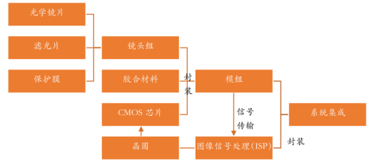
Fig. 3 Image Signal Processor (ISP)
Its functions include 3A, bad pixel correction, denoising, strong light suppression, backlight compensation, color enhancement, lens shading correction, and other processing.
2) Core Algorithm Chip for Image Signals
Currently, mainstream algorithm chip solutions mainly include:
(a) Embedded solutions, such as ARM, DSP, ASIC, MCU, SOC, FPGA, GPU, etc., among which ARM, DSP, ASIC, MCU, and SOC are software programmed and difficult to meet the response speed requirements in ADAS vision systems;
(b) Direct programming processing solutions, such as Field Programmable Gate Arrays (FPGA), are programmable devices with higher speed. FPGA programming and optimization are performed directly at the hardware level, resulting in significantly lower energy consumption. They are regarded as a recommended solution when balancing algorithms and processing speed, especially when used in pre-installed systems and when algorithm stability is required.
The current requirements for core algorithm chips include:
(a) The chip must meet automotive-grade standards, specifically the ASIL-B or even ASIL-D level in the functional safety standards for road vehicles;
(b) High bandwidth, especially for multi-sensor fusion chips, requires higher chip frequencies and heterogeneous designs;
(c) Hardware deep learning designs must meet artificial intelligence computing model requirements;
(d) Lower cost and energy consumption to facilitate promotion in the intelligent automotive field.
3) Deep Learning Methods
(a) Deep learning originates from research on artificial neural networks and is a method of representation learning based on data in machine learning.
(b) Deep learning, with multiple hidden layers in a multilayer perceptron, is a structure of deep learning. Observations (such as an image) can be represented in various ways, such as a vector of pixel intensity values or more abstractly as a series of edges and areas of specific shapes;
(c) Deep learning forms more abstract high-level representations of attribute categories or features by combining low-level features to discover distributed feature representations of the data;
(d) The advantage of deep learning is that it replaces manual feature extraction with efficient algorithms for unsupervised or semi-supervised feature learning and hierarchical feature extraction.
(e) Convolutional Neural Networks (CNNs) are the first true multilayer structured learning algorithms that reduce the number of parameters to improve training performance by utilizing spatial relationships;
(f) Deep learning methods also distinguish between supervised and unsupervised learning. The learning models established under different learning frameworks vary significantly. For example, Convolutional Neural Networks (CNNs) are a machine learning model under deep supervised learning, while Deep Belief Nets (DBNs) are a model under unsupervised learning.
1.3 Field Programmable Gate Array (FPGA) Boards (see Fig. 4)
Comprehensive Analysis of Autonomous Driving Technology and Examples
Fig. 4 Field Programmable Gate Array (FPGA) Boards
FPGA has a large number of register resources, making it very capable of handling complex high-speed control applications and data processing, from small MP3 devices to large satellites and spacecraft. The development of PLD (Programmable Logic Device) has gone through:
(a) Programmable Read Only Memory (PROM);
(b) Programmable Logic Array (PLA);
(c) Programmable Array Logic (PAL); Generic Array Logic (GAL);
(d) Complex Programmable Logic Device (CPLD);
(e) Field Programmable Gate Array (FPGA) stage.
Compared to traditional logic circuits and gate arrays (such as PAL, GAL, and CPLD devices), FPGAs have different structures. FPGAs use small lookup tables (16×1 RAM) to implement combinational logic, with each lookup table connected to the input of a D flip-flop, which drives other logic circuits or I/O, forming a basic logic unit module that can implement both combinational logic functions and sequential logic functions. These modules are interconnected using metal wiring or connected to I/O modules.
1.4 360° Imaging System Image Stitching Technology
The 360° panoramic imaging system image stitching technology installs multiple ultra-wide-angle cameras around the vehicle, simultaneously capturing images around the vehicle. After correction and stitching by the image processing unit, it can form a panoramic top view of the vehicle (see Fig. 2). On the screen, one can intuitively see the vehicle’s position and the obstacles around the vehicle, allowing for smooth parking or navigating through complex terrain.
Comprehensive Analysis of Autonomous Driving Technology and Examples
Fig. 5 360° Panoramic Imaging System Image
1.5 Millimeter Wave Radar Can Monitor Vehicle Operations Over a Large Area
Microwave radar operates similarly to laser radar, but it emits radio waves instead of lasers. Microwave radar is low-cost and compact, but its accuracy is inferior to that of laser radar. Millimeter waves have wavelengths between centimeter waves and light waves, and they possess the advantages of both microwave guidance and photoelectric guidance:
(a) Its larger wavelength can penetrate fog, smoke, dust, etc., obstacles that laser radar struggles to penetrate, making it more immune to adverse weather;
(b) Compared to centimeter wave guidance heads, millimeter wave guidance heads are smaller, lighter, and have higher spatial resolution;
(c) Compared to infrared and laser optical guidance heads, millimeter wave guidance heads have strong penetration abilities through fog, smoke, and dust, long transmission distances, and are effective in all-weather and all-time conditions;
(d) Millimeter wave radar has stable performance and is not disturbed by the shape or color of target objects. It effectively compensates for the usage scenarios that other sensors like infrared, laser, ultrasound, and cameras lack in onboard applications.
These characteristics enable millimeter wave radar to monitor vehicle operations over a large area, and its detection of information such as the speed, acceleration, and distance of vehicles in front is also more precise, making it the preferred sensor for Adaptive Cruise Control (ACC) and Automatic Emergency Braking (AEB). Currently, 24GHz millimeter wave radar systems are the market’s main products, while 77GHz millimeter wave radar systems are the future trend.
Comprehensive Analysis of Autonomous Driving Technology and ExamplesComprehensive Analysis of Autonomous Driving Technology and Examples
Fig. 6 Millimeter Wave Radar Product Appearance and Structure
Millimeter wave radar (see Fig. 6) typically has a detection range of 150m to 250m, with some high-performance millimeter wave radars achieving detection ranges of up to 300m, meeting the demand for large-range detection when vehicles are moving at high speeds. Millimeter wave radar is applied in automotive collision avoidance systems, with its basic principle (see Fig. 7): onboard millimeter wave radar continuously detects the relative speed and distance to front or rear obstacles by emitting electromagnetic waves that reflect off obstacles.
Comprehensive Analysis of Autonomous Driving Technology and Examples
Fig. 7 Automotive Collision Radar Principle Diagram
When the vehicle is in motion, the radar narrow beam emitted by the transmitter sends frequency-modulated continuous wave (FMCW) signals forward. When the emitted signal encounters a target, it is reflected back and received by the same antenna. After mixed frequency amplification processing:
(a) The time difference in the difference beat signal indicates the distance to the target;
(b) The difference frequency signal’s relationship with relative speed calculates the target’s relative speed and danger time;
(c) Thus, the collision avoidance system can make predictive warnings for the vehicle.
1.6 Laser Radar Will Become an Irreplaceable Sensor
Laser radar (see Fig. 8) uses lasers for detection and measurement. Its precision is excellent. The principle is to emit pulsed lasers around and calculate the distance based on the time difference of the return signal, thus establishing a three-dimensional model of the surrounding environment.
(1) Laser radar has very superior performance
(a) Laser radar has high resolution and long detection distances, over 200 meters;
(b) The short wavelength of lasers allows for the detection of very small targets;
(c) Laser radar can achieve extremely high angular, distance, and speed resolution, utilizing Doppler imaging technology to obtain very clear images;
(d) Laser propagation is linear, with good directionality, and the beam is very narrow, with very low dispersion, resulting in high detection accuracy;
(e) Lasers have strong resistance to active interference. There are few signal sources in nature that can interfere with laser radar.
(2) Types of Automotive Laser Radar
Comprehensive Analysis of Autonomous Driving Technology and Examples
Fig. 8 Different Specifications of Automotive Laser Radar Products
Laser radar is a radar system that detects the position, speed, and other characteristics of targets by emitting laser beams. The laser wavelength ranges from 0.5μm to 10μm, utilizing photoelectric detectors as receivers. According to radar frequency bands, it can be divided into ultra-long-distance radar, microwave radar, millimeter wave radar, and laser radar.
(3) Spatial Modeling of Laser Radar
Three-dimensional laser radar is typically installed on the roof of the vehicle and can rotate at high speeds, with the main functions:
(a) To obtain point cloud data of the surrounding space and instantly draw a three-dimensional spatial map around the vehicle;
(b) To measure the distance, speed, acceleration, and angular velocity of surrounding vehicles in three directions;
(c) To calculate the vehicle’s position by combining GPS maps;
The vast and rich data information is transmitted to the ECU, and after analysis and processing, it can provide rapid decision-making for the vehicle.
(4) Automotive Laser Radar Solutions
Laser radar should ideally be made compact and embedded directly into the vehicle body, meaning that mechanical rotating parts must be minimized. Many manufacturers have switched to fixed laser light sources that change the direction of the laser beam through internal glass rotation to meet the needs for multi-angle detection.
Automotive laser radar solutions can be divided into map-centered and vehicle-centered approaches:
(a) Map-centered: Laser radar can create high-precision maps, as seen in driverless cars from internet companies like Google and Baidu;
(b) Vehicle-centered: For entire vehicle companies, a laser radar product specifically tailored for vehicles is required. Different vehicles have their own requirements for laser radar products.
1.7 High-Precision Map System
1) High-precision maps are navigation maps for autonomous vehicles
Traditional navigation maps (see Fig. 9 (a)) are for manually driven cars, while high-precision maps (see Fig. 9 (b)) are for autonomous vehicles, with real-time, complex road conditions, and high reliability as additional automotive-grade requirements, achieving centimeter-level precision.
Currently, high-precision maps have auxiliary environmental perception functions: detailed road information is marked on high-precision maps to assist vehicles in the perception process for verification. For example, if a vehicle’s sensor detects a pothole on the road ahead, it can compare this with the data on the high-precision map. If the same pothole is also marked on the map, it can serve as a verification judgment.
Comprehensive Analysis of Autonomous Driving Technology and Examples
2) Composition of High-Precision Maps
High-precision maps are divided into two levels (see Fig. 10), with the bottom layer being static high-precision maps and the upper layer being dynamic high-precision maps, which include:
(a) Lane models: guiding vehicles from point A to point B, including detailed information and connection relationships on the lane;
(b) Road components (Objects): including traffic signs, indication boards, gantries, road poles, and various objects on the roadside and roadway. When the vehicle’s sensor detects these road objects, it can compare with the map to know the vehicle’s precise position;
(c) Road attributes: including road curvature, heading, slope, and cross slope, assisting vehicles in executing steering and acceleration/deceleration;
(d) Feature layers for multi-sensor positioning.
Comprehensive Analysis of Autonomous Driving Technology and Examples
Fig. 10 Composition of High-Precision Maps
Dynamic high-precision maps are updated timely to reflect changes in the road network, such as worn lane markings and repainted lines, changes in traffic signs, traffic congestion, construction situations, traffic accidents, and weather conditions. These changes must be promptly reflected on high-precision maps to ensure the safe operation of driverless vehicles.
4) Main Differences Between Navigation Maps and High-Precision Maps
The main differences lie in the different users, purposes, systems, elements, and attributes involved.
(a) The user of navigation maps is people
Navigation maps are used for manual navigation and searches, belonging to in-car infotainment systems, equipped with displays. In terms of elements and attributes, navigation maps only include simple road lines, points of interest (POI), administrative boundary lines, and basic road navigation functions, including path planning from point A to point B, vehicle positioning, and road matching.
(b) The user of high-precision maps is computers
High-precision maps belong to in-car safety systems, containing mathematical attributes such as curvature, slope, heading, and cross slope (see Fig. 11). They are used for high-precision positioning, auxiliary environmental perception, planning, and decision-making, including detailed road models, lane models, road components, road attributes, and other positioning layers. They facilitate high-precision positioning functions, road-level and lane-level planning capabilities, as well as lane-level guiding capabilities.
Comprehensive Analysis of Autonomous Driving Technology and Examples
Fig. 11 Road Mathematical Attributes
5) Classification of High-Precision Map Levels
The precision of high-precision maps is divided into two dimensions: one is the precision of the map itself, and the other is the precision of real-time accurate positioning of autonomous vehicles on high-precision maps. The industry requires that all products control within 10cm.
In terms of data accuracy and richness, high-precision map levels are set to three levels, namely:
(a)L2 level (for ADAS): known in the industry as ADAS Vector Map;
(b)L3 level high-precision map: also known as Vector Map, Intensity Map, Objects Map;
(c)L4 level high-precision map: known in the industry as Occupancy Map.
For high-precision maps, real-time updates are essential. To achieve L3 level and higher autonomous driving, high-precision maps must be used.
Currently, high-precision map collection solutions are based on mobile measurement technology, which involves higher precision scanning and processing of road surface information to generate maps. Utilizing 32-line/16-line onboard laser radar + cameras to collect road data, AI algorithms + three-dimensional human-computer interaction software complete map drawing, achieving precision within 5-10 centimeters.
Comprehensive Analysis of Autonomous Driving Technology and Examples
5) ADAS (Active Safety Scene) Maps
ADAS (Active Safety Scene) maps are intermediary between ordinary navigation electronic maps and high-precision maps. ADAS does not require very high precision for maps, but it needs to add some ADAS attributes, such as curvature, slope, heading angle, and more precise lane counts, resulting in relatively low production costs.
(a) Based on current vehicle speed, braking speed, and driver reaction time, an adaptive speed recommendation (ASR) function is provided;
(b) It will remind users to slow down 50-300 meters in advance;
(c) In curved road sections, ASR will calculate reasonable vehicle speeds considering road width, lane count, and overall road conditions, reminding users to slow down.
1.8 High-Precision Positioning
High-precision positioning: compares the environmental information perceived by the autonomous vehicle’s sensors with high-precision maps to obtain the vehicle’s precise location on the map. High-precision maps play a role in high-precision positioning, auxiliary environmental perception, planning, and decision-making. Autonomous driving utilizes artificial intelligence algorithms to make decisions, planning lanes and paths, issuing commands to controllers for braking, steering, and acceleration to control the vehicle towards its destination.
(1) Structure of the High-Precision Positioning System
The high-precision positioning system consists of mobile stations and local base stations (see Fig. 10). Mobile stations are installed in vehicles, while local base stations are installed on rooftops.
Comprehensive Analysis of Autonomous Driving Technology and Examples
Fig. 13 High-Precision Positioning System
(a) Local base stations are the reference framework for the entire positioning system, continuously tracking and observing satellite signals over the long term, wirelessly broadcasting differential correction information in real-time, and providing high-precision carrier phase differential (Real-time Kinematic, RTK) data and starting coordinates for each mobile station in the vehicles in real-time.
(b) Mobile stations receive satellite signals from space and local base station data, performing real-time RTK calculations to obtain centimeter-level high-precision real-time coordinates.
Comprehensive Analysis of Autonomous Driving Technology and Examples
Fig. 14 Schematic of Onboard Mobile Station
2
The Decision System of Autonomous Driving
The autonomous driving decision system is responsible for route planning and real-time navigation. Planning and real-time navigation require not only high-precision digital maps but also support from V2X communication network technologies.
2.1 Operating System for Autonomous Driving
(a) The operating system supports the basic operations of the computer, such as task scheduling, executing applications, and controlling external devices;
(b) The autonomous driving operating system must unify and coordinate the various hardware sensors such as radars, cameras, and sonars into a cohesive system;
(c) The autonomous driving operating system must be built with advanced artificial intelligence to guide the operation of the autonomous driving AI system;
(d) The operating system of autonomous vehicles must be absolutely safe and reliable, supporting both basic and advanced functions of the vehicle while providing real-time feedback on received data;
(e) Autonomous driving requires an extremely stringent operating system that must know the vehicle’s current location, understand the surroundings, anticipate what will happen next, and determine how to respond;
(f) In terms of complexity and monitoring breadth, the operating system for autonomous driving should outperform computer or smartphone operating systems.
2.2 ARM Embedded Linux System
(a) The ARM Embedded Linux operating system. The development of ARM-Linux programs is mainly divided into three categories: application program development, driver program development, and system kernel development, each with distinct characteristics for different types of software development.
(b) The three core capabilities of the operating system for autonomous vehicles are real-time feedback, complete reliability, and perception capabilities that surpass human capabilities. The operating system managing the autonomous vehicle must respond with microsecond-level precision.
2.3 Autonomous Driving Processor (Chip)
NVIDIA’s latest autonomous driving processor performs 300 trillion operations per second with only 30 watts of power. The image shows the interfaces supported for radars, sensors, and cameras.
Fig. 15 Xavier Chip Board
2.4 Algorithms
Adaptive algorithms for different speed conditions are modeled (see Fig. 16), where the sum of the current heading angle and the anticipated heading change serves as the heading feedback, and the difference between the expected heading and the heading feedback is used as the input deviation for the classic PID controller to calculate the desired front wheel angle δ.
Comprehensive Analysis of Autonomous Driving Technology and Examples
Fig. 16 Trajectory Tracking Algorithm Model
The predictive model is the basic theoretical basis for controlling the electric steering actuator.
3
The Execution System of Autonomous Driving
The execution system is also a bottom-level control system, responsible for executing specific operations of the vehicle’s braking, acceleration, and steering. Engineers control the steering wheel and throttle through specialized “drive-by-wire devices,” replacing the human driver’s hands and feet.
3.1 Drive-By-Wire Devices
Drive-by-wire is a specific term in the electromechanical industry, referring to a physical control method of electromechanical control. The drive-by-wire system replaces mechanical or hydraulic systems with electric systems. It mainly refers to the connection method between the signal generator and the signal receiver, which is transmitted through cables or other actions to connect the objects.
In simple terms, the drive-by-wire execution of autonomous vehicles mainly includes drive-by-wire steering, throttle, and braking. The most challenging part is the braking in drive-by-wire execution.
(1) Drive-By-Wire Steering System
The drive-by-wire steering system (Steer By Wire, SBW) eliminates the mechanical connection between the steering wheel and the steering wheel, offering better maneuverability and stability, and serves as a method for active steering intervention. The structure of the SBW system is shown in the following figure (17), primarily divided into three parts:
(a) Steering wheel system, including the steering wheel, torque sensor, steering angle sensor, torque feedback electric motor, and mechanical transmission device;
(b) Electronic control system, including vehicle speed sensors, with the option to add yaw rate sensors, acceleration sensors, and electronic control units to enhance vehicle maneuverability;
(c) Steering system, including angle displacement sensors, steering motors, gear rack steering mechanisms, and other mechanical steering devices.
Comprehensive Analysis of Autonomous Driving Technology and Examples
Fig. 17 Structure of Drive-By-Wire Steering System (Steer By Wire, SBW)
(2) Electric Power Steering System
Comprehensive Analysis of Autonomous Driving Technology and Examples
Fig. 18 Contact Electric Power Steering Assembly and Principle
(3) Drive-By-Wire Throttle System
(a) Advantages of the Drive-By-Wire Throttle System
It features sensitivity and precision, allowing the engine to accurately adjust the air-fuel ratio based on various driving information, improving combustion conditions and enhancing power and fuel economy. It can also integrate with electronic signals for oil pressure, temperature, and exhaust recirculation to reduce emissions. By reducing mechanical components, it lightens the mechanical structure and lowers the chances of mechanical part maintenance.
(b) Components of the Drive-By-Wire Throttle System
The drive-by-wire throttle mainly consists of a throttle pedal, pedal position sensor, electronic control unit (ECU), data bus, motor, and throttle actuator.
(c) Working Principle of the Drive-By-Wire Throttle System
The displacement sensor is installed inside the throttle pedal, constantly monitoring the position of the throttle pedal. When a change in the throttle pedal height is detected, this information is instantly transmitted to the servo motor, which drives the throttle actuator to control the throttle.
(4) Drive-By-Wire Braking System
The active safety drive-by-wire braking function (Brake by wire) is composed of an electronic control unit and sensors, currently including:
(a) Electronic Brake Assist (EBA); (b) Adaptive Cruise Control (ACC); (c) Stop-and-Go System (SMS); (d) Electronic Stability Control (ESC); (e) Active Collision Avoidance System (ABC); (f) Hill Hold System (HHS); (g) Electronic Parking Brake (EBC); (h) Automatic Parking System (ASC);
Comprehensive Analysis of Autonomous Driving Technology and Examples
Fig. 19 Anti-lock Braking System (ABS) Principle Diagram
(5) CAN Bus Protocol
(a) CAN (Controller Area Network): a serial communication network that enables distributed real-time control. CAN was developed by Bosch in Germany (along with Intel). (Understanding: Through the CAN controller, multiple microprocessors (CPUs) can form a local area network, i.e., a controller area network.
(b) Advantages of CAN: It enables widespread application. For example, it has a maximum transmission speed of 1Mbps, a communication distance of up to 10km, a lossless arbitration mechanism, and a multi-master structure. The price of CAN controllers is decreasing, and many MCUs now integrate CAN controllers. Every vehicle is now equipped with a CAN bus.
(c) Applications of CAN
Comprehensive Analysis of Autonomous Driving Technology and Examples
Fig. 20 CAN Application Scenarios
(d) Classification of CAN Buses
CAN buses are divided into high-speed CAN buses and low-speed CAN buses. In vehicles, high-speed signals are used for electronic control systems like ABS, ESP, and TCU, which require real-time signal processing, so high-speed CAN signals are used; while basic devices like headlights do not require high-speed implementations, so low-speed CAN signals are used.
4
Communication Systems
4.1 V2X Communication Network Technology
V2X refers to the exchange of information between vehicles and the outside world, encompassing a series of in-vehicle communication technologies. V2X includes six categories: Vehicle-to-Vehicle (V2V), Vehicle-to-Roadside Equipment (V2R), Vehicle-to-Infrastructure (V2I), Vehicle-to-Pedestrian (V2P), Vehicle-to-Machine (V2M), and Vehicle-to-Bus (V2T). V2X is divided into:
Comprehensive Analysis of Autonomous Driving Technology and Examples 
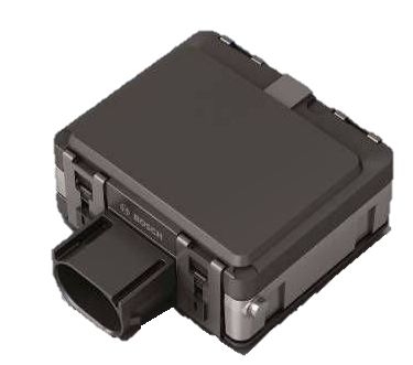
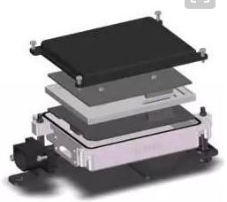
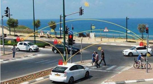
Fig. 21 V2X (Vehicle-to-Everything) Communication Modes
(a) Network-based communication mode, i.e., vehicle-to-network V2N (vehicle-to-network), such as communication via the internet;
(b) Direct communication mode, covering vehicle-to-vehicle V2V (vehicle-to-vehicle), vehicle-to-infrastructure V2I (vehicle-to-infrastructure), and vehicle-to-person V2P (vehicle-to-person), such as through 5G communication and Radio Frequency Identification (RFID) technology (see Fig. 21).
Comprehensive Analysis of Autonomous Driving Technology and Examples
Fig. 22 RFID Technology Used for Automotive Management
(c) The two transmission modes are complementary (see Fig. 22).
In simple terms, V2V is a more advanced technology than autonomous driving. Autonomous driving can achieve automatic following and detect traffic conditions about 200 meters ahead and make corresponding vehicle assistance actions, such as speed adjustments and automatic braking, but it cannot foresee the state of the vehicle ahead or whether an accident has occurred. These requirements rely on V2V technology support.
4.2 Electronic and Electrical Architecture
In simple terms, the automotive electronic and electrical architecture is the electrical system composed of various communication lines, electronic control chips, modern navigation systems, and intelligent automotive networks within the vehicle. The Electrical/Electronic Architecture (EEA) concept was proposed by Delphi, integrating the design principles of automotive electronic and electrical systems, central electrical box design, connector design, and electronic electrical distribution systems into a comprehensive vehicle electronic and electrical solution.
Through EEA design, powertrains, driving information, entertainment information, and other vehicle information can be transformed into actual physical layouts of power distribution, signal networks, data networks, diagnostics, fault tolerance, and energy management electronic and electrical solutions. Optimizing automotive electronic and electrical architecture design can enhance the overall performance of the vehicle while controlling and reducing the total weight and production costs, which is of significant practical importance for the further development of the modern automotive manufacturing industry.
4.3 Safety Solutions
Automotive safety mainly refers to the two major components of safety design and safety operation, which can be further subdivided into operational safety, environmental safety, behavioral safety, functional safety, quality safety, mechanism safety, and safety evolution.
4.4 Cloud Platform
(1) The cloud primarily provides two major functions, including distributed computing and distributed storage. The first application of the cloud platform is simulation, as shown in Fig. 23.
Comprehensive Analysis of Autonomous Driving Technology and Examples
Fig. 23 Cloud Platform Simulation
(2) High-Definition Map Generation
As shown in Fig. 24, generating high-definition maps is a complex process involving many steps, including raw data processing, point cloud generation, point cloud alignment, 2D reflection map generation, high-precision map marking, and final map generation.
Comprehensive Analysis of Autonomous Driving Technology and Examples
Fig. 24 High-Definition Map Generation Process
(3) Deep Learning Model Training
Autonomous driving utilizes various deep learning models, necessitating continuous updates to ensure their effectiveness and efficiency. Given the massive volume of raw data, it’s challenging to quickly complete model training relying solely on a single machine; hence, it is essential to develop highly scalable distributed deep learning systems.
5
Examples of Autonomous Driving Vehicles
1. Hardware Systems of Autonomous Vehicles
The hardware system for autonomous driving can be roughly divided into three parts: perception, decision, and control (with additional modules for positioning, mapping, prediction, etc.).
Comprehensive Analysis of Autonomous Driving Technology and Examples
Fig. 25 Hardware System of Autonomous Driving
(1) Sensors Used in Autonomous Driving Vehicles
The perception sensors used in autonomous driving mainly include laser radar, millimeter wave radar, cameras, and combined navigation systems.
Comprehensive Analysis of Autonomous Driving Technology and Examples
Fig. 23 Perception Sensors
(a) Laser Radar: Installed on the roof, it rotates 360 degrees to provide point cloud information around it. Laser radar is used not only for vehicle perception but also for positioning and creating high-precision maps.
(b) Cameras: Light passes through the lens and filter to the back-end CMOS or CCD integrated circuit, converting the light signal into an electrical signal, which is then processed by an image processor (ISP) into standard formats like RAW, RGB, or YUV, and transmitted to the computing unit via a data transmission interface.
(c) Millimeter Wave Radar: Similar to laser radar, it emits a beam of electromagnetic waves and calculates distance and speed by observing the difference between the return and incoming waves, mainly divided into 24G and 77G, installed on the bumper.
(d) Combined Navigation: GNSS + INS fusion forms the combined navigation system. First, the GNSS card receives GPS and RTK signals through an antenna to calculate its spatial position. Second, when the vehicle travels under trees or near buildings, GPS may lose signal or produce multipath effects, leading to positioning deviations. In such cases, INS information fusion is needed for combined computation.
(2) Applicable Scope of Sensor Design (Table 1)
Comprehensive Analysis of Autonomous Driving Technology and Examples
Table 1 Applicable Scope of Sensor Design
(3) Relationship Between Sensors and Vehicle Speed
(a) Braking Distances and Reference Values at Different Speeds (Table 2)
Comprehensive Analysis of Autonomous Driving Technology and Examples
Table 2 Braking Distance Calculation Formulas and Reference Values at Different Speeds
Currently, the speed limit on urban closed roads in China is 80, and the maximum speed limit on highways is 120. The formula can be used to calculate braking distances. At a speed limit of 120, a detection range of at least 150 meters is required.
(b) Braking Distance Calculation Formulas and Reference Values at Different Speeds (Table 3)
Comprehensive Analysis of Autonomous Driving Technology and Examples
Table 2 Braking Distance Calculation Formulas and Reference Values at Different Speeds
At a speed limit of 120, it would be better if the braking distance could reach 200 meters.
(4) Relationship Between Sensors and Resolution (See Fig. 24)
Comprehensive Analysis of Autonomous Driving Technology and Examples
Fig. 24 Relationship Between Sensors and Resolution
Resolution is calculated using the inverse tangent function.
2. Computing Units of Autonomous Driving Vehicles
Comprehensive Analysis of Autonomous Driving Technology and Examples
Fig. 25 Computing Unit of Autonomous Driving Vehicles
(a) PCI-Express (Peripheral Component Interconnect Express) is a high-speed serial computer expansion bus standard;
(b) Ethernet is a technology for local area networks. Ethernet is currently the most widely used local area network technology, replacing other LAN standards such as Token Ring, FDDI, and ARCNET;
(c) CAN stands for Controller Area Network, developed by Bosch, a company known for developing and producing automotive electronics, and has ultimately become an international standard (ISO 11898), being one of the most widely used field buses internationally.
3. Drive-By-Wire Systems in Autonomous Vehicles
Comprehensive Analysis of Autonomous Driving Technology and Examples
Fig. 26 Drive-By-Wire System Assembly
The drive-by-wire system of autonomous vehicles is divided into three main parts: deceleration, steering, and acceleration.
(a) Drive-By-Wire Steering System of Autonomous Vehicles
Comprehensive Analysis of Autonomous Driving Technology and Examples
(b) Drive-By-Wire Acceleration System of Autonomous Vehicles
Comprehensive Analysis of Autonomous Driving Technology and Examples
(c) Drive-By-Wire Braking System. The MK C1 integrates the brake assist and brake pressure control modules (ABS, ESC) into one braking unit, and when this fails, the MK 100 ensures redundancy.
Comprehensive Analysis of Autonomous Driving Technology and Examples
4. Examples of Autonomous Vehicles
1) Tesla’s Autopilot 2.0 Autonomous Vehicle
Comprehensive Analysis of Autonomous Driving Technology and Examples
Fig. 30 Tesla’s Autopilot 2.0 Autonomous Vehicle
(a) The vehicle is equipped with 8 cameras (3 front cameras with different perspectives: wide-angle, telephoto, and medium; 2 side cameras (one left and one right); 3 rear cameras; 12 ultrasonic sensors (doubling the detection range); one front radar (enhanced version); and one rear reversing camera), achieving 360-degree coverage with a maximum detection range of 250 meters;
(b) Equipped with 12 ultrasonic front radars that can penetrate rain, fog, and dust environments, enhancing the detection data of the visual system;
(c) The enhanced millimeter wave radar can operate in adverse weather and detect vehicles ahead;
(d) The vehicle’s mainboard integrates the Nvidia PX2 processing chip, with computing power 40 times higher than the first generation of autonomous driving systems, significantly improving computational capabilities.
2) Apollo 2.5 Autonomous Vehicle
Comprehensive Analysis of Autonomous Driving Technology and Examples
Fig. 31 Apollo 2.5 Autonomous Vehicle
Apollo 2.5 (vision-based high-speed autonomous driving in limited areas) supports two new hardware systems: the first set is Hesai’s Pandora kit + 2 wide-angle cameras + 1 millimeter wave radar; the second set is a monocular wide-angle camera + 1 millimeter wave radar.
3) Dongfeng L4 Autonomous Intelligent Truck
The L4 intelligent truck features an adaptive cruise system and lane-keeping capabilities for automatic following and complete autonomous steering in curves.
Comprehensive Analysis of Autonomous Driving Technology and Examples
Fig. 32 Dongfeng L4 Autonomous Intelligent Truck
4) Shenzhen Autonomous Driving Bus
The bus is equipped with laser radar, millimeter wave radar, cameras, GPS antennas, etc., achieving pedestrian and vehicle detection, deceleration avoidance, emergency stopping, obstacle detouring, lane changing, and automatic stop at stations under autonomous driving.
Comprehensive Analysis of Autonomous Driving Technology and Examples
Fig. 33 Shenzhen Autonomous Driving Bus
There are dozens of groups covering the automotive industry, key components, new energy vehicles, intelligent connected vehicles, aftermarket, automotive investment, autonomous driving, and the Internet of Vehicles. Please scan the administrator’s WeChat to join the group (please indicate your company name). Additionally, there is a financing group for startups, welcoming angel round and Series A companies to join.
Comprehensive Analysis of Autonomous Driving Technology and Examples

Leave a Comment