Introduction
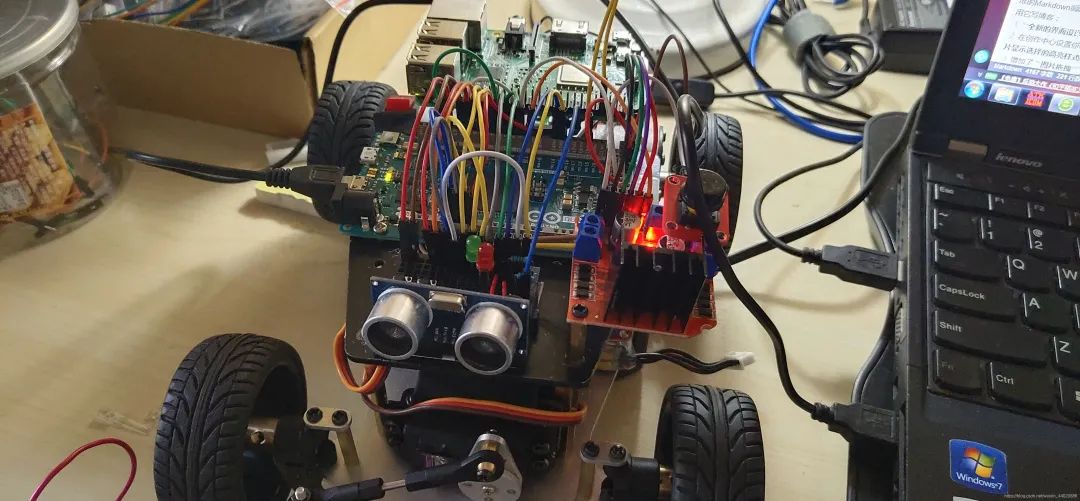
During the pandemic, feeling a bit bored, I bought a smart car chassis and a bunch of parts on Taobao, developed based on Arduino Due and Raspberry Pi. The Due is responsible for low-level control, while the Raspberry Pi is used for high-level controller development, such as Stanley controller or model predictive controller for trajectory tracking.
This time, we use the Simulink toolchain to complete the task. All the code for the car is based on the Simulink Target Support Package.
Required Hardware & Software
1. Ordinary DC motor with encoder. 2. Arduino Due control board and data cable (similar to dSPACE MAB for RCP development, but the performance is not comparable at all, just kidding). 3. Matlab & Simulink R2019b (any civilian version is fine). 4. A computer.
Preparation Work
(1) Install Arduino Hardware Support Package
This is not the focus of this article; there are many tutorials available online, including similar video tutorials recorded by MATLAB. Interested students can refer to relevant materials, which are very simple. Here’s a similar tutorial.
https://blog.csdn.net/u013732401/article/details/70161200
(2) Simulink Model
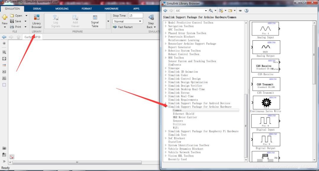
Create a new Simulink Model and open the Library Browser. Find the Simulink Support Package for Arduino Hardware.
Build the model as shown in the figure below. The Tachometer module is in the Sensor module of the hardware support package (available in 2019b, but not in lower versions like 2018a, which requires capturing the rising or falling edge of the encoder pulse manually). The model for capturing the high and low levels is built in the Encoder submodule of the DrivePID example in the hardware support package.
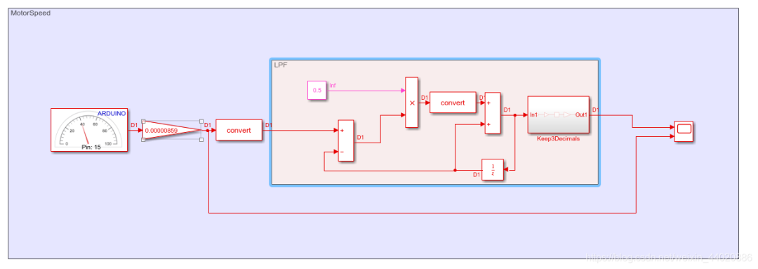
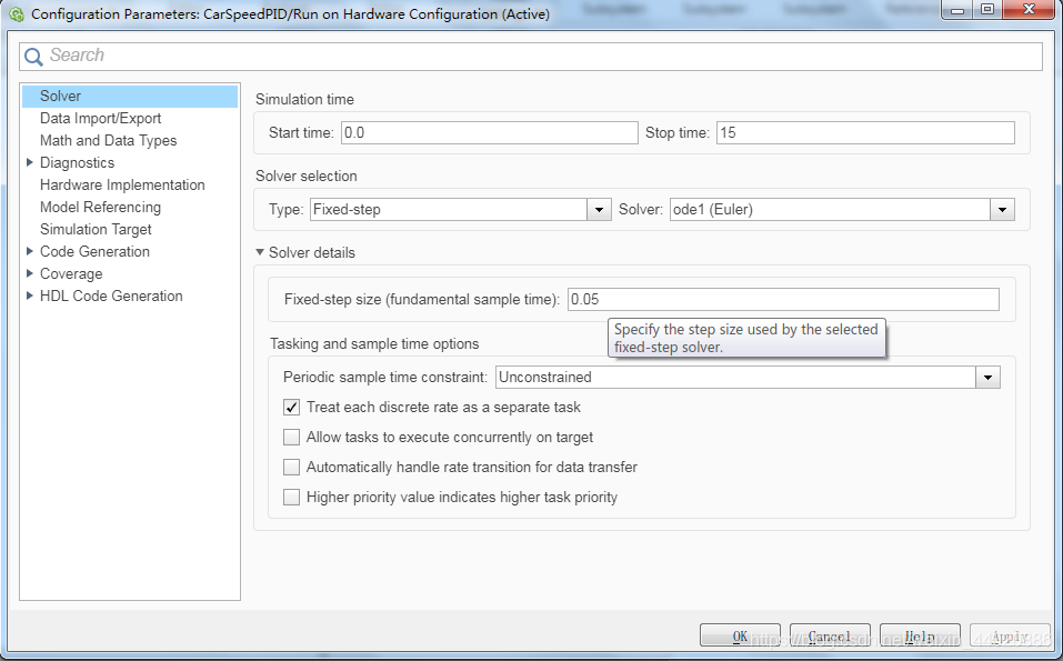
As you can see, the output of the Tachometer is not the RPM mentioned in the help, but rather pulses per minute. The settings in the Tachometer module are connected to the PIN of the single signal line of the encoder (using only one signal line makes it impossible to measure direction, please note that the encoder signal line operates at 5V voltage, while the microcontroller used in this project has a maximum IO tolerance of 3.3V, requiring basic knowledge to build a voltage divider circuit. If you use other chips, please check the data sheet for the maximum tolerable voltage of that IO port). Set the sampling time to 0.05. Since my smart car collects 390 pulses for one wheel rotation and the wheel diameter is 64 mm, simple calculations can yield the wheel speed in meters per second. After this, a first-order low-pass filter is applied, which can be found online regarding the formula for first-order low-pass filtering, so I won’t elaborate here.
Next, we will build the drive module. Regarding the use of the L298N drive module, I will use one motor for debugging, setting pins 29 and 27 to high and low, and pin 2 to ENA. In the Arduino support package, the PWM module input value of 0-255 corresponds to a duty cycle of 0-100%, with a PWM frequency fixed at 1 kHz in Due.
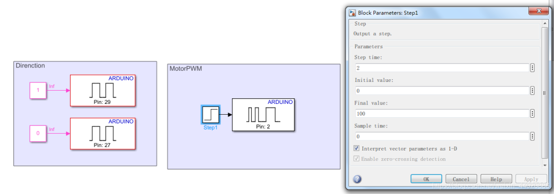
The purpose of the Step signal is to simulate a step input at 2 seconds of simulation time, changing the duty cycle to 100. What we need to do is record data, noting the simulation time, input, and output. How to record? We need to right-click on the corresponding signal line and select Log Selected Signals. We will log the Step output line and the low-pass filtered speed. Finally, set the Arduino external simulation debugging environment.
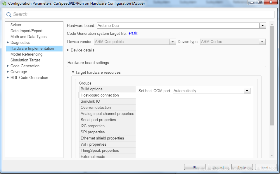
In the Set COM port section, you can manually enter your hardware serial port number if the program upload fails. Next, proceed with online debugging, similar to the debug mode in Keil software. For those using versions below 2019b, click the drop-down menu next to the simulation button and select External mode. I cannot perform data logging in version 2018a, but data can be transmitted via the serial port; please refer to relevant materials.
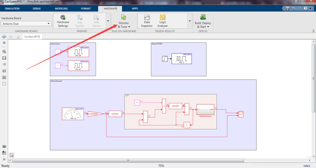
Click the button to start offline simulation; the model will compile into code and be flashed into the hardware. The preparation work is complete. I believe that whether using model-based design or manually writing code, completing the above work will not be difficult. Now let’s get into the main topic of this tutorial.
Main Topic
Export Data to Workspace
As shown in the figure, click on Data Inspector
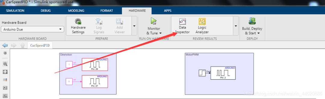
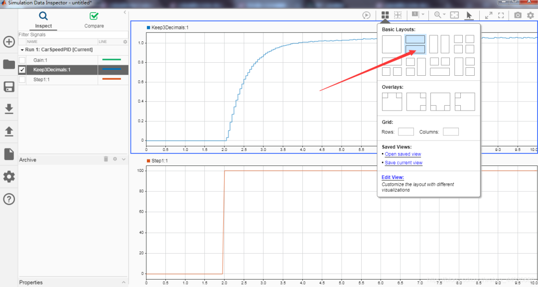
Drag the data from the left into the corresponding block diagram to view the data recording effect. If you already have a car and have performed open-loop PWM speed measurement, you need to pay attention to each step below. As long as you have the corresponding PWM and speed values, you can use the following method for PID speed control, not limited to using Arduino or similar rapid prototyping development. As shown, right-click on the data to export it to the Workspace.
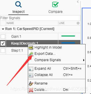
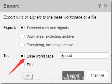
Similarly, export both sets of data, namely PWM and Speed.
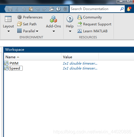
Return to the main MATLAB interface, and you will see the following in the workspace.
Use the code to parse the data, as shown in the figure below.
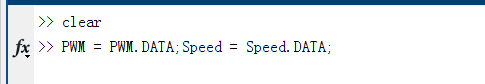
Looking at the workspace content, we can obtain the familiar data types.
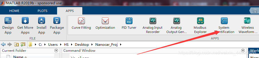
System Identification
We can identify the transfer function of the car drive based on the input and output using the System Identification toolbox in MATLAB, and then proceed with PID tuning. The specific method is as follows. Open the System Identification toolbox.
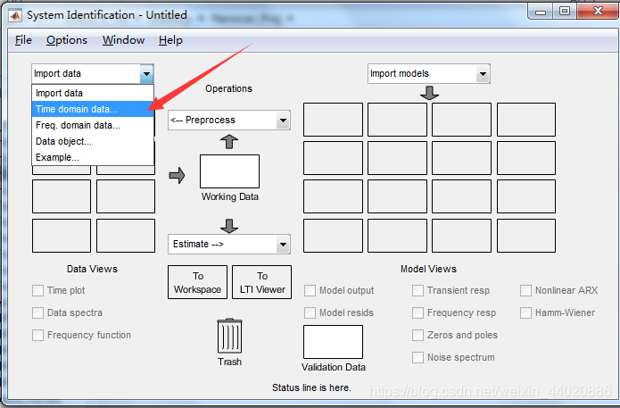
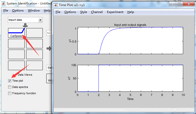
Import the time-domain data.
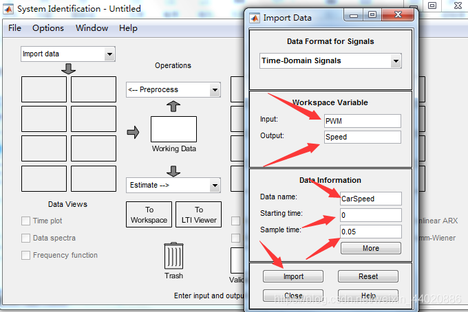
After importing, click on the imported curve, then click on Time Plot to view the curve.
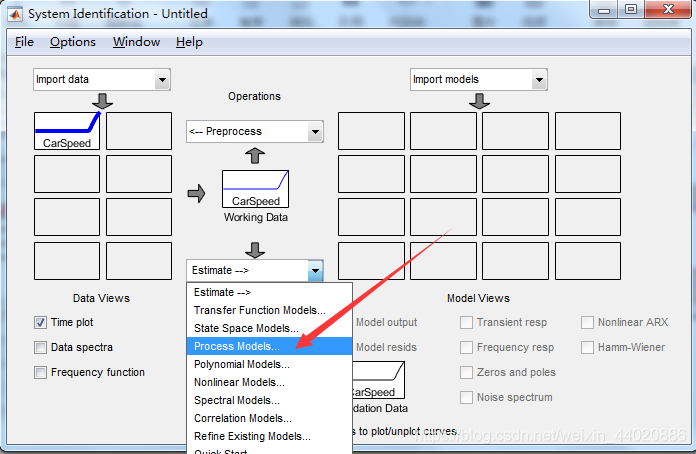
Then select the system estimation mode as shown in the figure.
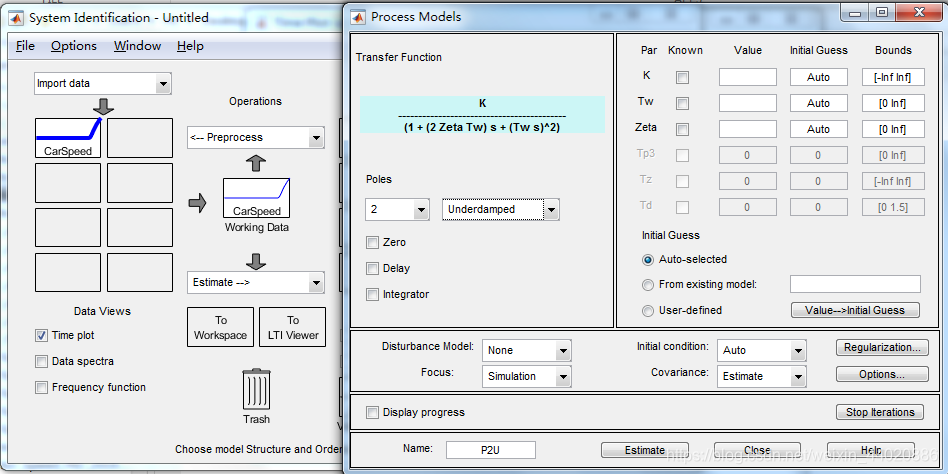
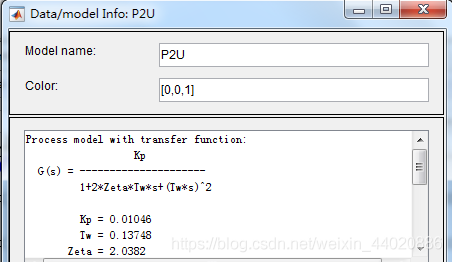
You can choose the structure of the transfer function to identify according to your needs; here I choose a second-order oscillatory model.
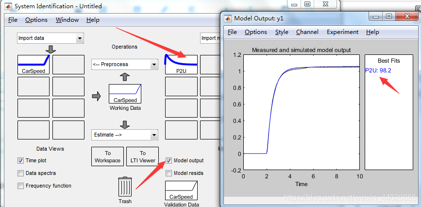
Then click Estimate, wait a moment, and you can view our identification results in the main interface of the toolbox. Highlight the identified curve, click Model Output to see the identified curve. The overlap I achieved reached 98.2. The effect is still considerable.
At the end of this step, right-click on the identified curve to obtain the required transfer function parameters.
Offline Simulation
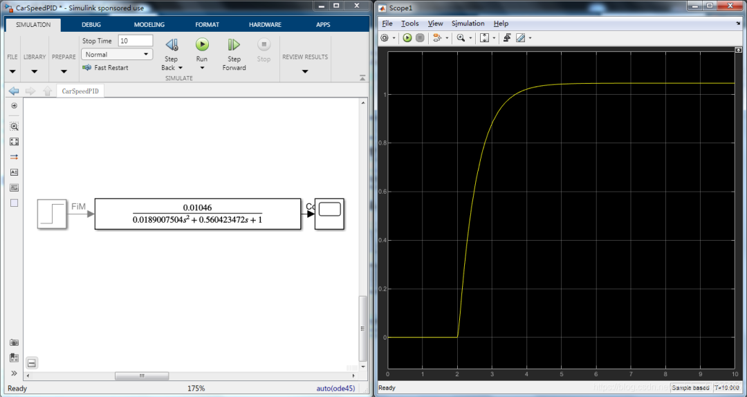
Obtaining the system’s transfer function is indeed a delightful thing. When learning control theory, the system model is always given first, but in actual projects, the model needs to be identified; this is the gap between textbooks and reality. Once we have the parameters, we can build the simulation environment in Simulink, inputting the parameters from the above figure into the Transfer Fcn module. Before simulation, since we are performing continuous system simulation, change the simulation time to variable step size. Check the simulation results, which should be consistent with the actual output.
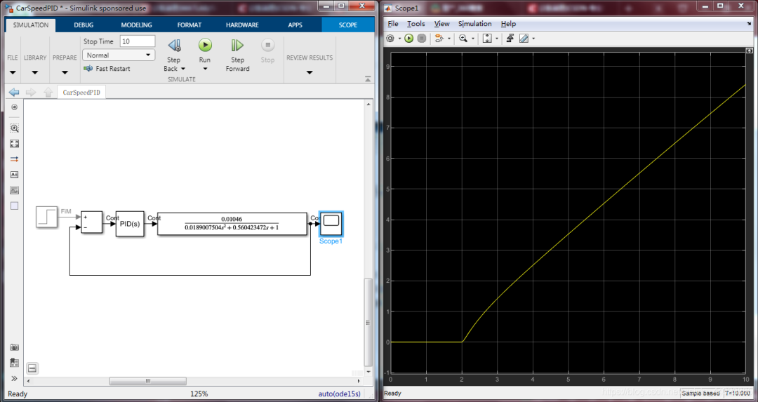
Since PID control is required, we can add a PID controller module to build the model, as shown below. A simple simulation shows that without changing any parameters of the PID module, the results are poor.
At this point, we need to open the PID module and click the Tune button, requesting MATLAB to help us with auto-tuning! The PID Tune App will then open automatically.
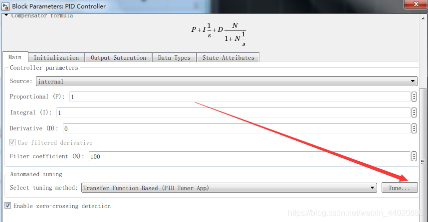
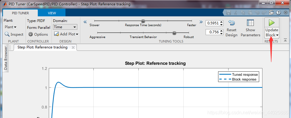
It seems to have completed the tuning function for you; you only need to adjust the Robust to Aggressive slider to observe the system’s response, choose your preferred position, and then click Update Block to update the parameters in your controller.
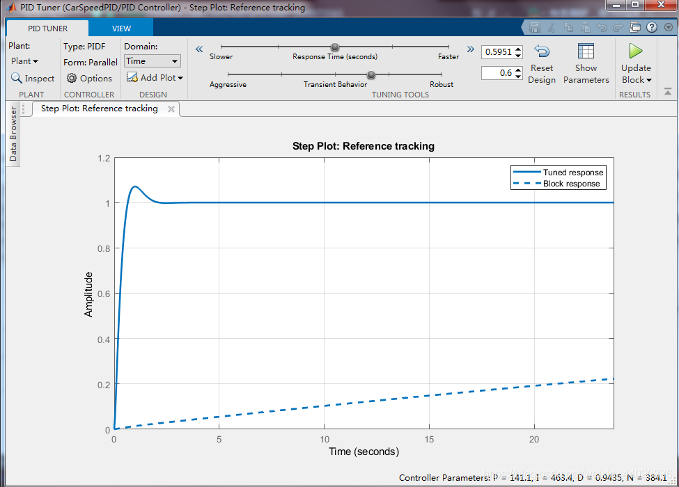
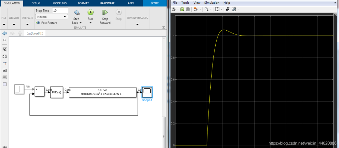
At this point, you will notice that the parameters of the PID module have been changed. Now, adjust the model in the Step module to set your desired speed, for example, I want the car to travel at a speed of 1 m/s. Click simulate to see the effect.
Controller Discretization
Isn’t it quite simple to complete PID tuning using the MATLAB/Simulink environment? Some students may ask, what’s the use of this; I need to run it on the board. Don’t worry; we are currently studying the S domain, and the computer controller is a discrete system. We need to convert the controller from the S domain to the Z domain. The steps are shown in the figure below.
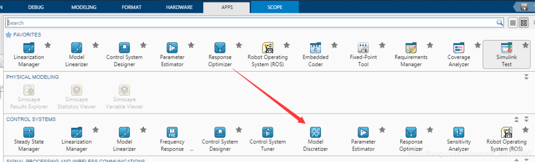
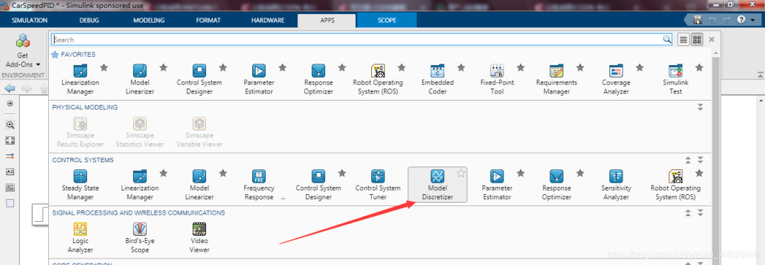
Users of 2019b can find this App in the following figure; users before 2019b can find it under Analysis -> Control Design -> Model Discretizer.
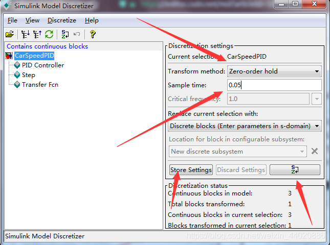
You can choose zero-order hold or first-order hold for discretization; I personally set the sampling time to 0.05s. Then click s -> z button and finally Store Setting.
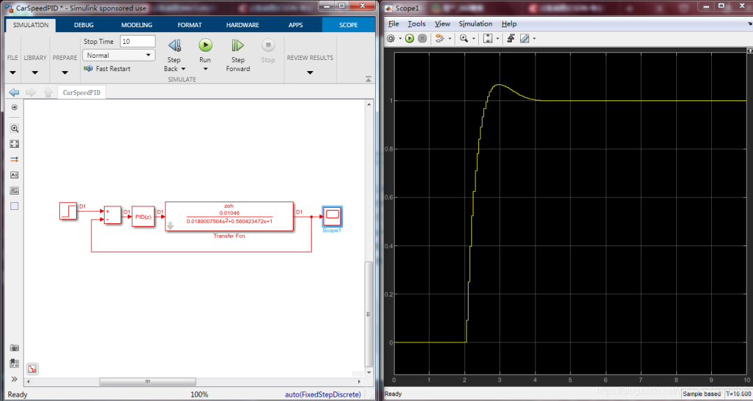
Return to the model, and you will see that both the algorithm and the model have been converted from the S domain to the Z domain. In the Solver, change the sampling time to fixed step size, set the sampling time to 0.05, and simulate again. Unfortunately, the model output is oscillating! At this point, you need to repeat the above steps and perform tuning again in PID tune. I will not repeat the steps; I will directly show the simulation results after tuning.
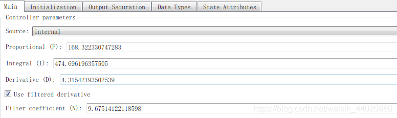
This is the final self-tuning PID parameters.
Real Vehicle Effect
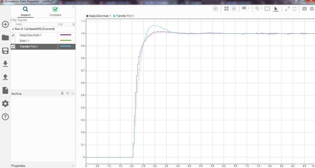
The simulation effect is acceptable; at this point, we have completed the design of the PID discrete controller. Next, we need to flash it onto the board. Change the model as shown in the figure below. Replace the transfer function model, and you can also perform a comparison. Replace the actual vehicle speed with the feedback value of the transfer function. Click on external mode simulation to see how the real vehicle performs.
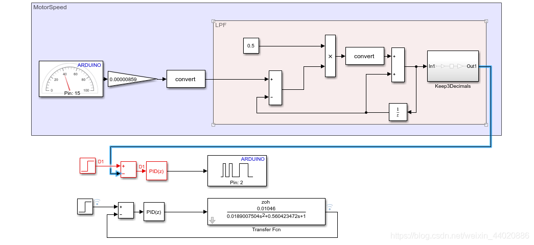
After the model automatically generates code and flashes it into the controller, the comparison between the real vehicle test and the simulation results is as follows. There are some differences in overshoot, but the actual controller has less overshoot. Finally, both tend to stabilize. The blue line is the simulation result, and the purple line is the actual controller effect.
Conclusion
Simulation can save us a lot of time. If you are developing manual code using STM32 or S12K, you can collect data via the serial port, import it into Excel, and then into MATLAB for system identification of the model. Generate the PID controller as an atomic subsystem, write a data dictionary to manage input and output signals and parameters (very important), and then use Embedded Coder to generate code, calling the generated code function in the interrupt service function. The model-based design approach can accelerate the development of controllers.
(This article is reproduced with permission from CSDN, author ScottieHan. Unauthorized reproduction and excerpting are prohibited.)