Click on the “Baijun Technology” above, select “Pin to Top”
Embedded essentials, delivered with one click
The enhanced version of the ARM Bare Metal Phase 1 video course, supporting Wiki Lesson 11: Using Serial Port (UART),
consists of 2 sections: Section 001: Auxiliary Line 1: Hardware Knowledge – Introduction to UART Hardware and Section 002: S3C2440_UART Programming, which discusses JZ2440 UART bare metal programming.
Text cannot completely replace video, so if you find these articles helpful but not fully understandable, it is recommended to purchase the video for further study.
Video purchase address: 100ask.taobao.com, as shown in the figure below

Section 001: Auxiliary Line 1: Hardware Knowledge – Introduction to UART Hardware
1. Introduction to Serial Port Hardware
The full name of UART is Universal Asynchronous Receiver and Transmitter, which means asynchronous sending and receiving. Serial ports are widely used in embedded systems:
-
Printing debug information
-
Connecting various modules: GPS, Bluetooth
Serial ports are popular due to their simple structure and reliable stability. Only three wires are needed: transmit, receive, and ground.
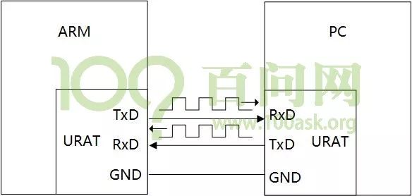
Through TxD->RxD, the information to be sent from the ARM development board is sent to the PC. Through RxD->TxD, the information to be sent from the PC is sent to the ARM development board. The ground wire at the bottom serves as a common reference ground.
2. Serial Port Parameters
-
Baud Rate: Common baud rates include 9600, 19200, 115200, etc. This indicates how many bits are transmitted per second.
-
Start Bit: A logical “0” signal is sent first to indicate the start of data transmission.
-
Data Bits: Can be 5~8 bits of logical “0” or “1“. For example, ASCII code (7 bits), extended BCD code (8 bits). Data is transmitted in little-endian format.
-
Parity Bit: This bit is added to the data bits to ensure that the number of “1” bits is even (even parity) or odd (odd parity), to verify the correctness of data transmission.
-
Stop Bit: This is a character data end marker.
How to send a byte of data, such as ‘A‘?
The ASCII value of ‘A‘ is 0x41, which is binary 01000001. How do we send this 8 bit data to the PC?
1. Both parties agree on the baud rate (the time each bit occupies)
2. Specify the transmission protocol
a. Originally high level, ARM pulls to low level, maintaining 1bit time;
b. The PC starts timing at the low level;
c. ARM drives the level of TxD according to the data sequentially, while the PC reads the level of RxD pin to obtain the data;
The previous figure mentioned logical levels, meaning the pin level representing signal 1 is artificially defined. The figure shows the waveform when transmitting ‘A‘ under TTL/CMOS logic levels:
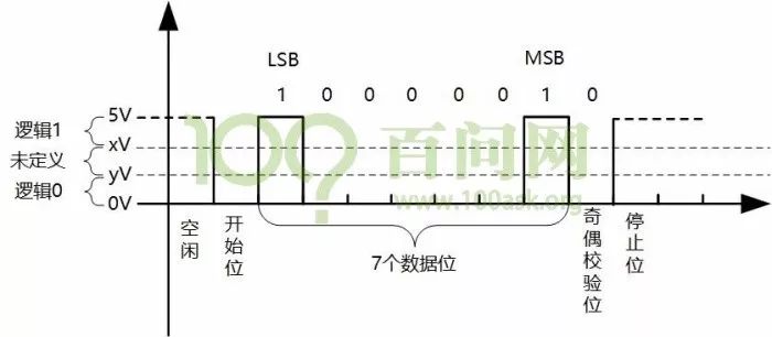
Between xV and 5V, it is considered logic 1, and between 0V and yV it is considered logic 0.
The figure shows the waveform when transmitting ‘A‘ under RS-232 logic levels:
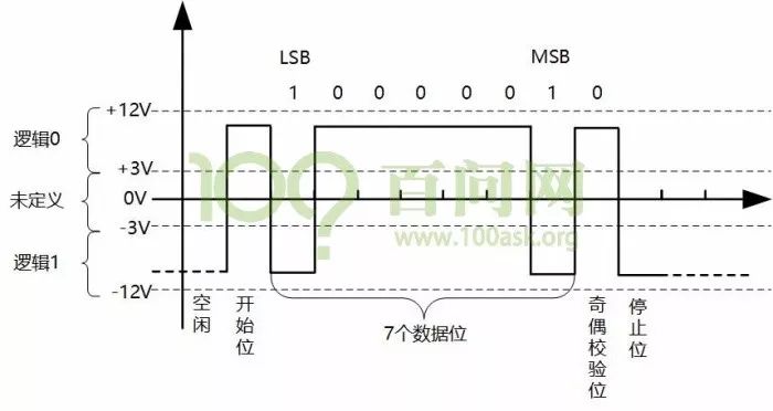
Between -12V and -3V, it is considered logic 1, and between +3V and +12V it is considered logic 0.
RS-232 levels are higher than TTL/CMOS, allowing for longer transmission distances, and are more commonly used in industry.
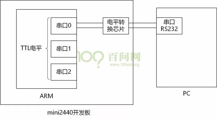
Most ARM chips on the market have more than one serial port, typically using serial port 0 for debugging, while using other serial ports for external modules.
Serial ports on ARM chips are all TTL levels, and through a level conversion chip on the board or external, they are converted to RS232 interface, connecting to the computer’s RS232 serial port for data transmission between the two:
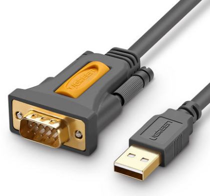
Nowadays, fewer and fewer computers have RS232 serial ports; almost all have USB ports. Therefore, using a USB serial chip to convert the TTL level on the ARM chip into USB serial level allows the development board to transmit data to the computer via USB.
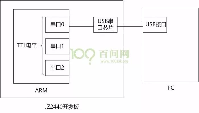
The above two methods have the same programming operations for the ARM chip.
How does the ARM chip send/receive data?
The structure diagram of the JZ2440 serial port is shown below:
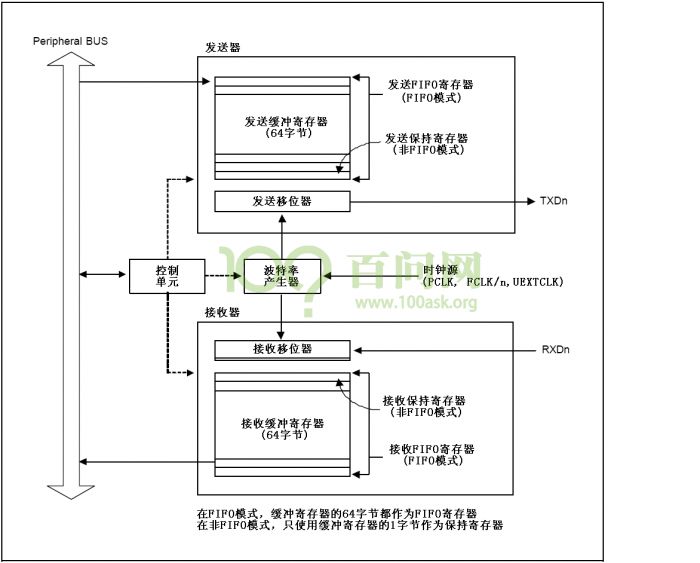
From the above figure, to send data, the CPU controls the memory to send data via FIFO to UART, and the shifter inside the UART sends the data out sequentially, generating an interrupt to notify the CPU when transmission is complete.
When receiving data, the level of the receive pin is acquired, bit by bit, placed into the receive shifter, and then into FIFO, writing to memory. An interrupt is generated to notify the CPU when transmission is complete.
Section 002: S3C2440_UART Programming
In the file uart.c, you need to write these functions:
uart0_init(): used to initialize the serial port
putchar(): used to send a character
getchar(): used to receive a character
puts(): used to send a string of characters
The function of uart0_init() is as follows:
-
1. Set the pins for the serial port: Set GPH2,3 for TxD0, RxD0 according to the schematic and reference manual, and to keep them high, first set them to pull-up:
GPHCON & = ~((3<<4) | (3<<6));
GPHCON | = ((2<<4) | (2<<6));
GPHUP & = ~((1<<2) | (1<<3)); /* Enable internal pull-up */
-
2. Set the baud rate
UCON0 = 0x00000005; //Set the uart clock to PCLK, interrupt/polling mode:
uart clock=50M, assuming the baud rate is 115200,
According to the formula
UBRDIVn = (int)( UARTclock / ( baud rate x 16) ) –1
we get
UBRDIVn = (int)(50000000 / ( 115200 x 16) ) –1 = 26
UBRDIV0 = 26;
-
3. Set the data format
The data format is set to the commonly used 8n1: 8 data bits, no parity bit, and 1 stop bit
ULCON0 = 0x00000003; /* 8n1: 8 data bits, no parity bit, 1 stop bit */
Read the UTRSTAT0 register to check its second bit to determine if the send buffer is empty, meaning the last send is complete. If completed, write new data to UTXH0; check its first bit to determine if the receive buffer is empty, meaning this receive is complete. If complete, read the value of URXH0.
int putchar(int c)
{
while (!(UTRSTAT0 & (1<<2)));
UTXH0 = (unsigned char)c;
}
int getchar(void)
{
while (!(UTRSTAT0 & (1<<0)));
return URXH0;
}
Looping to output characters will achieve string output:
int puts(constchar*s)
{
while (*s)
{
putchar(*s);
s++;
}
}
In the main.c main function, first call the initialization function uart0_init(), then loop to get the input data, and echo it back. When receiving `
` (carriage return), output `
` (new line); sometimes `
` indicates a carriage return, thus output `
` (new line).
The main.c code is as follows:
#include “s3c2440_soc.h”
#include “uart.h”
int main(void)
{
unsigned char c;
uart0_init();
puts(“Hello, world!\n\r“);
while(1)
{
c = getchar();
if (c ==‘\r’)
{
putchar(‘\n’);
}
if (c ==‘\n’)
{
putchar(‘\r’);
}
putchar(c);
}
return0;
}
// PS: Due to space limitations, not all code is provided here. For experiments, please download the relevant code from Baidu Cloud: https://eyun.baidu.com/s/3b1UtLc
Recommended reading: S3C2440 clock system & programming to improve running clock

You can also click 【Read Original】 to preview the course.