
UART is an asynchronous full-duplex serial communication protocol consisting of two data lines, Tx and Rx. Since there is no reference clock signal, both parties in communication must agree on serial baud rate, data bit width, parity bit, stop bit, and other configuration parameters to communicate at the same rate.
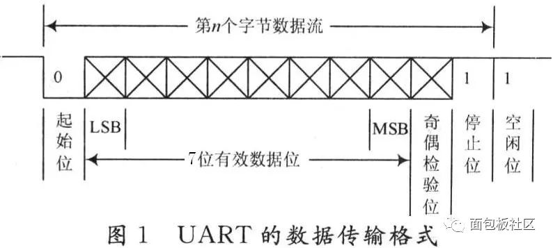
Start Bit: A logical “0” signal is sent first, indicating the beginning of character transmission;Data Bit: Can be 5 to 8 bits of logical “0” or “1”; for example, ASCII code (7 bits), extended BCD code (8 bits); transmitted in little-endian format, meaning LSB is sent first, followed by MSB;Parity Bit: After adding this bit to the data bits, the number of “1” bits should be even (even parity) or odd (odd parity);Stop Bit: It is an end marker for character data. It can be 1 bit, 1.5 bits, or 2 bits of high level (used for synchronization between both parties; the longer the stop bit time interval, the stronger the fault tolerance);Idle Bit: In a logical “1” state, indicating that there is no data transmission on the current line;
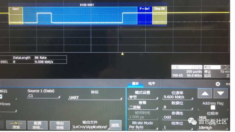
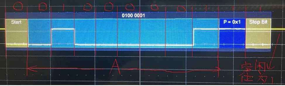
Baud Rate: This parameter is often confused with bit rate, but they are distinct. However, I believe that the baud rate in UART can be considered as bit rate, meaning the number of bits transmitted per second. Common baud rates include 9600, 19200, 115200, etc., which indicate the number of bits transmitted per second. Start Bit: A logical “0” signal is sent first, indicating the start of data transmission. Data Bit: The selectable values are 5, 6, 7, or 8 bits, which can transmit that many bits of 0 or 1. It is best to use 8, because if this value is lower when transmitting ASCII values, parsing will generally encounter issues. The reason is simple: an ASCII character is 8 bits; if a frame’s data bits are 7, then one bit is uncertain, leading to errors. Parity Bit: After adding this bit to the data bits, the number of “1” bits should be even (even parity) or odd (odd parity) to verify the correctness of data transmission. For example, when transmitting “A” (01000001): 1. For odd parity: Among the 8 bits of the character “A”, there are two “1”s, so the parity bit must be “1” to maintain an odd count of “1”s (odd parity). The waveform in Figure-1 illustrates this case. 2. For even parity: Among the 8 bits of the character “A”, there are two “1”s, so the parity bit must be “0” to maintain an even count of “1”s (even parity). This bit can also be omitted; it is not necessary to have a parity bit. Stop Bit: It is an end marker for a frame of data. It can be 1 bit, 1.5 bits, or 2 bits of idle level. Some might find it strange to have 1.5 bits, but it does exist. Thus, when generating this UART signal, I use two waveform points to represent one bit. This doesn’t need to be delved into deeply… Idle Bit: The voltage state on the line when no data is being transmitted. It is in a logical “1” state. Transmission Direction: Indicates whether data is transmitted starting from the high bit (MSB) or low bit (LSB). For instance, when transmitting “A”, if it is MSB, it would be 01000001 (as shown in Figure-2), and if it is LSB, it would be 10000010 (as shown in Figure-4). The order of data transmission in UART is: first the start bit is transmitted, followed by the data bits, then the parity bit (if needed), and finally the stop bit. This completes the transmission of one frame of data. The process continues like this. Additionally, I should mention one parameter: Frame Interval: This is the size of the interval between frames of transmitted data, which can be measured in bits or time (knowing the baud rate allows for conversion between bit count and time). For example, after transmitting “A”, that constitutes one frame of data, and when transmitting “B”, the interval between A and B is the frame interval.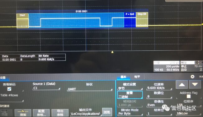 ↑ Figure-3
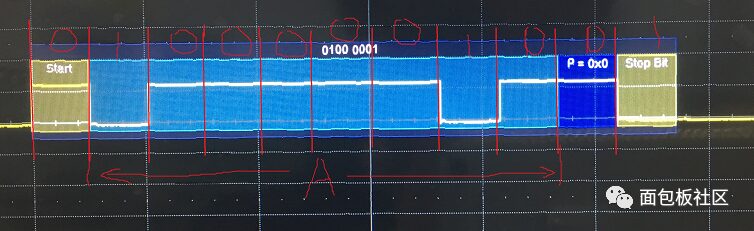 ↑ Figure-4
Copyright Statement: This article is sourced from the internet, freely sharing knowledge, and the copyright belongs to the original author. If there are copyright issues, please contact me for removal.
You may also like:
Essentials | What are Processor Microarchitecture and Instruction Set?
Sharing an Embedded Software Tools List!
Sharing a Compact and Useful Code Comparison Tool
A Multi-Task Management OS Implemented in Over 300 Lines of Code
Sharing Several Useful Shell Scripts in Embedded Systems!
Reply with 1024 in the chat interface of the public account to obtain embedded resources; reply with m to view the article summary.
Click Read Original to see more shares.