Wu Jianying Microcontroller Development Board Address
Taobao Store:【Wu Jianying’s Shop】
Address:【https://item.taobao.com/item.htm?_u=ukgdp5a7629&id=524088004171】
UART is a chip used to control communication between computers and serial devices. One important point to note is that it provides a data terminal equipment interface, allowing the computer to communicate with modems or other serial devices using the RS-232C interface. As part of the interface, UART also provides the following functionalities:
Converts parallel data transmitted from the computer into an output serial data stream;
Converts incoming serial data from external devices into bytes for internal use by parallel data devices;
Adds parity bits to the output serial data stream and checks the parity of incoming data streams;
Adds start and stop markers to the output data stream and removes them from the received data stream;
Handles interrupt signals from keyboards or mice (keyboards and mice are also serial devices);
Manages synchronization issues between the computer and external serial devices;
The asynchronous serial communication protocol works by transmitting each character of data serially, one bit at a time. As shown in the figure below:
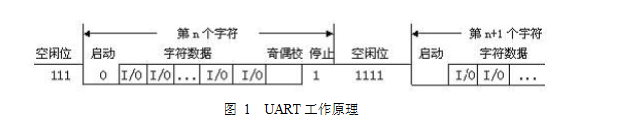
Each bit has the following meanings:
Start Bit: Sends a logic “0” signal to indicate the beginning of character transmission.
Data Bits: Follow the start bit. The number of data bits can be 4, 5, 6, 7, or 8, forming a character. Typically, ASCII code is used. Transmission starts from the least significant bit, synchronized by the clock.
Parity Bit: This bit follows the data bits, ensuring the number of “1” bits is even (even parity) or odd (odd parity), which verifies the correctness of data transmission.
Stop Bit: This signifies the end of a character data. It can be 1, 1.5, or 2 bits of high level (logic “1”).
Idle Bit: In a logic “1” state, indicating that no data is currently being transmitted on the line.
Baud Rate: A measure of data transmission speed, represented as the number of bits transmitted per second. For example, if the data transfer rate is 120 characters per second and each character is 10 bits, the baud rate is:
10 × 120 = 1200 characters/second = 1200 baud.
The above data bits, parity bits, baud rate, etc., can all be set in the COM interface. They can also be set in code for each bit of the UART register, with the meanings of each bit as follows:
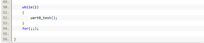
Below are a few small programs to understand the process of data transmission using the UART communication protocol:
<p style=”text-align: center;”></p style=”text-align: center;”>
Here we use the uart_init function to complete the setting of each bit of UART. Now let’s take a look at how uart_init is defined in the system:
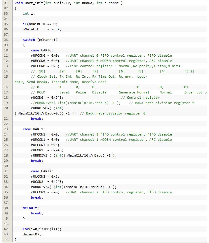
UART0 — UART2 are the three registers provided by the development board for us, with the settings of the UART registers completed through the assignment of rUFCON, rUMCON, rULCON, rUCON, rUBRDIV, etc.
If you like this article, please give it a thumbs up


|
Technology Comes from Accumulation, Success Comes from Persistence —— Microcontroller Expert Wu Jianying |