Communication Between S7-300/400 and SINAMICS S120 via DP Bus
1. Overview of DP Bus Communication Functionality
S7-300/400 can communicate with SINAMICS S120 via DP bus for both periodic and non-periodic data communication. Using standard S7 function blocks SFC14/SFC15, the S7-300/400 PLC can send Control Word 1 (CTW1) and Main Set Value (NSETP_B) to the drive through PROFIBUS periodic communication; using standard S7 function blocks SFC58/SFC59, non-periodic data exchange can be achieved to read or write parameters of the drive.
2. Connection between S7-300/400 and S120 Devices

3. Setting the Drive Station Address
1. There are two methods to set the PROFIBUS communication address for the drive:
(1) Set the address using the dip switch on the CU control unit, with valid address values ranging from 1 to 126. The address setting in this example is shown in the figure below.
Note: The power to the inverter should be turned off when changing the address via the dip switch.
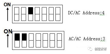
(2) When all dip switches are set to OFF or ON, the address can be set using parameter P918; otherwise, the address set in parameter P918 is invalid.
The default baud rate for the drive’s PROFIBUS communication is: 1.5Mbps.
2. The drive station address set in the hardware configuration of S7-300/400 should match the station address of the drive.
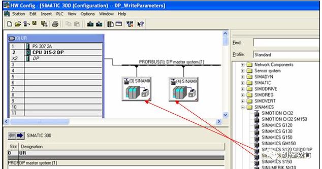
Figure 1
4. Communication Message Settings
For different drive devices, only specific message structures can be selected. Please refer to the SINAMICS_S120_Commissioning_Manual for detailed descriptions. Table 1 lists commonly used messages.
Table 1.
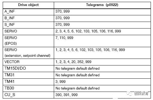
Message format 999 is a user-defined message. When this message format is selected, the motor’s start/stop control bits must be associated by the user. At this time, the PLC control request must be set to 1 (P854=1).
Note: Users can configure the message structure as needed during the hardware configuration of S7-300/400. After configuration, compile and save; then open Starter to verify if the message structure is consistent. If not, adjustments should be made in Starter by opening “configuration” and clicking the “Transfer to HW config” button.
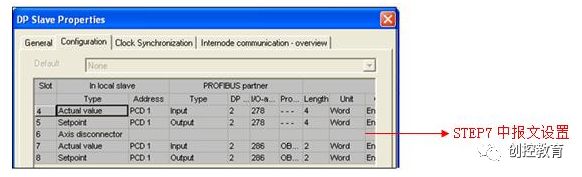
Figure 2
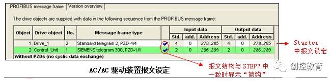
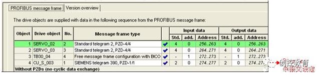
Figure 3 DC/AC Drive Message Settings
5. Using DP Bus for Motor Start, Stop, and Speed Control
S7-300/400 PLC sends Control Word 1 (CTW1) and Main Set Value (NSETP_B) to the drive through PROFIBUS periodic communication.
(1) Bit0 of the control word is used for motor start and stop control.
(2) The main set value is the speed set value; frequency set and actual values must be normalized so that 4000H (hexadecimal) corresponds to 100%, and the maximum frequency (maximum value) sent is 7FFFH (200%). The reference frequency can be modified in P2000 (default value is 50Hz).
(3) When the configured message structure is PZD=2 or free message 999, the “MOVE” instruction can be used for data transfer in S7-300/400; when the configured message structure is PZD>2, SFC14 and SFC15 system function blocks must be called in S7-300/400.
• SFC14 (“DPRD_DAT”) is used to read process data from the Profibus slave.
• SFC15 (“DPWR_DAT”) is used to write process data to the Profibus slave.
Example: SERVO_02 Program for Sending Control Word, Main Set Value and Reading Status Word, Actual Frequency
(1) To control the drive to run:
First send Control Word (STW1) 047E, then send 047F to start the drive. This data control word is specified in DB10.DBW8 (see Figure 4), and the main set value is set in DB10.DBD10, with the run signal being M1.0. These values are all set and monitored through the variable table VAT_2. The control program is shown in Figure 3.
(2) To stop the drive:
Send Control Word 047E to the drive.
(3) Read the drive status word and actual frequency value:
The PLC receives status word 1 (ZSW1), stored in DB10.DBW0; receives the actual frequency value from the drive, stored in DB10.DBD2.
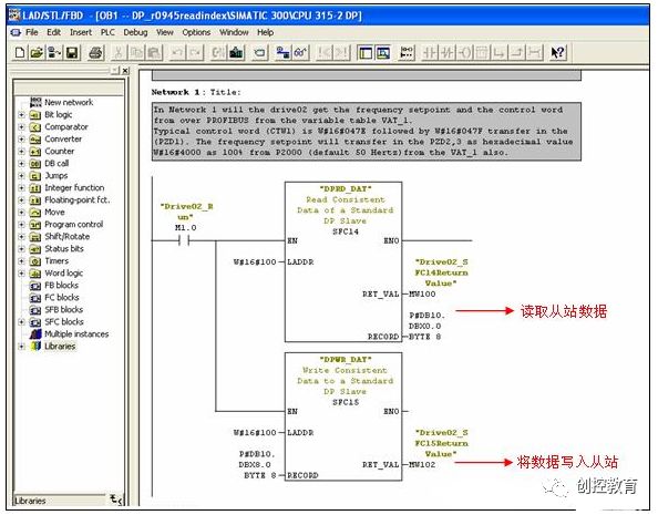
Figure 3. Control Program
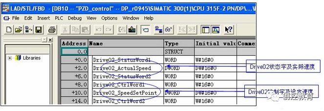
Figure 4. DB10
6. Reading and Writing Drive Parameters
1. Extended PROFIBUS DP Function (DPV1)
Non-periodic data transfer mode allows:
• Exchange of a large amount of user data (up to 240 bytes)
• Non-periodic data exchange can be achieved using DPV1 functions READ and WRITE. The content of transmitted data blocks should comply with the PROFIdrive parameter channel (DPV1) dataset DS47 (non-periodic parameter channel structure).
2. Structure of Parameter Request and Parameter Response
A parameter request includes three parts: request header, parameter address, and parameter value.
Table 2. Parameter Request Format

Table 3. Parameter Response Format
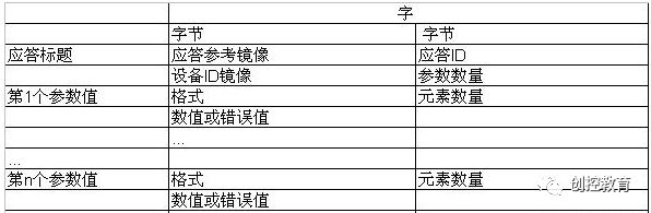
Table 4. Description of Parameter Requests and Responses
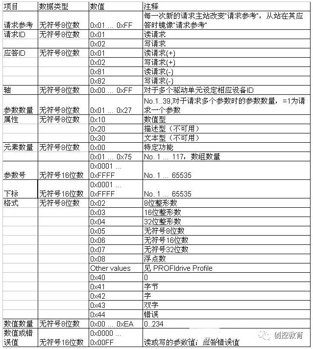
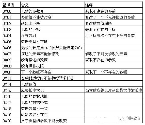
Table 5. Error Value Descriptions in DPV1 Parameter Response
3. S7-300/400 PLC reads drive parameters via PROFIBUS non-periodic communication.
Please note: When the PLC reads drive parameters, it must use two function blocks SFC58/SFC59 (program refer to Figure 5).
Example as follows:
(1) Use flag M10.0 and function block SFC58 to send a write request (data set RECORD DB1) (see Figure 6) to the drive.
Set M10.0 to 1 to start the write request. After the write request is completed, M10.0 must be set to 0 to end the request. MW108 (RET_VAL) displays the error code, indicating any error that occurred during the function processing. For error descriptions, please refer to “System Functions/Function Block Help”.
(2) Then, use flag M10.1 and function block SFC59 to send a read request to the drive, and the drive returns the parameter value response (response block DB2) (see Figure 7). Set M10.1 to 1 to start the read request. After the read request is completed, M10.1 must be set to 0 to end the request. MW110 (RET_VAL) displays the error code, indicating any error that occurred during the function processing. For error descriptions, please refer to “System Functions/Function Block Help”.
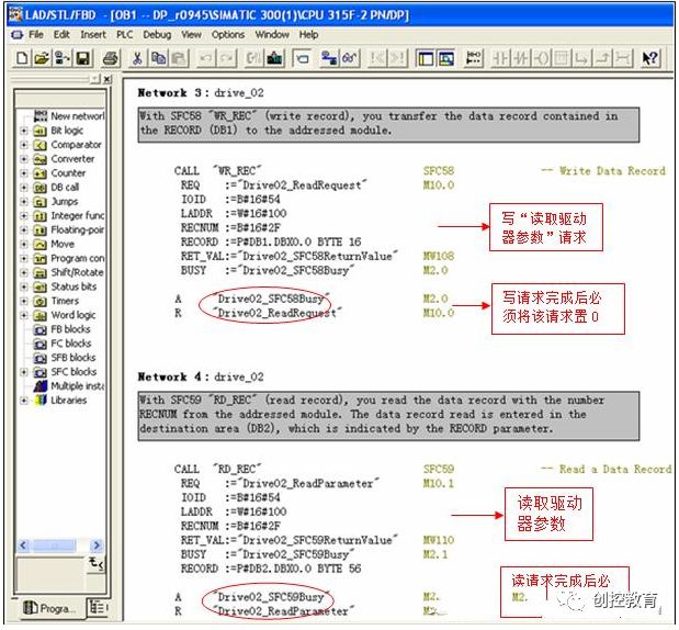
Figure 5. Reading Drive Parameter Program
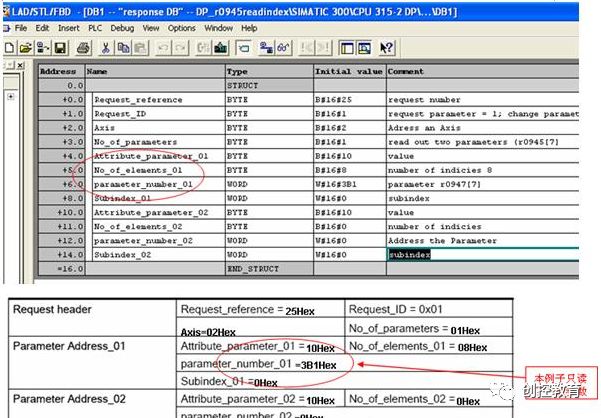
Figure 6. “Write” Request Data Block DB1
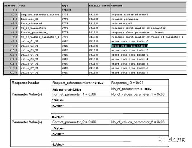
Figure 7. Drive Returns Parameter Value Data Block DB2
4. S7-300/400 PLC writes drive parameter P1217 via PROFIBUS non-periodic communication.
Example as follows:
The PLC only needs to use SFC58 to send a write request DB1 (see Figure 9) to the drive in Network 3 of this project; when the PLC reads the “write parameter” response, it needs to use SFC59 to read the parameter value data block returned by the drive as DB2 (see Figure 10). The program is shown in Figure 8.
(1) Set M10.0 to 1 to start the write request. After the write request is completed, M10.0 must be set to 0 to end the request. MW108 (RET_VAL) displays the error code, indicating any error that occurred during the function processing. For all error descriptions, please refer to “System Functions/Function Block Help”.
(2) Set M10.1 to 1 to start the read request. After the read request is completed, M10.1 must be set to 0 to end the request. MW110 (RET_VAL) displays the error code, indicating any error that occurred during the function processing. For error descriptions, please refer to “System Functions/Function Block Help”.
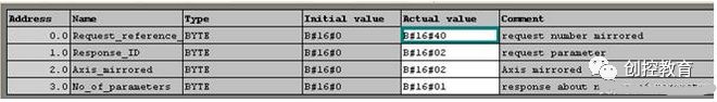 Figure 10. Data Block DB2 Returned by Drive
(Source: Network, Copyright belongs to the original author)
Disclaimer: This article is a network reprint or adaptation, copyright belongs to the original author. If it involves copyright, please contact for deletion! No one or organization assumes relevant legal responsibility.