
The origin of this project stems from a discussion about the RP2040 MCU (the first microcontroller from Raspberry Pi).
At the time, we were discussing how to build a simple desktop/graphical user interface for the RP2040 MCU, and I casually mentioned, “Why not just run some old operating systems?” After saying that, I suddenly thought of the original Macintosh.
The Macintosh was first released 40 years ago as a hardware device that was very simple yet quite cool. However, it had limited memory: the initial 128KB version was insufficient, and it was replaced by the 512K Macintosh just a few months later, indicating that 512K seemed more appropriate.
Despite this, the 128KB version could still run some real applications. Although it did not have MultiFinder or true multitasking capabilities at the time, I still found it quite charming.
In 1984, the price of a Mac was about one-third of that of a VW Golf (Volkswagen Golf, a compact family car). But now, I want to try using this RP2040 microcontroller board that costs £3.80 (approximately ¥34.8) to see if I can replicate it: the RP2040 has 264KB of memory, leaving plenty of space after deducting the Mac’s 128KB—how cool would it be if I could get it up and running quickly and play with Mac on it?
After some time, I really did it:
You might not believe it, but I completed this high-quality project in a short amount of time. Software was obviously the most critical part, and I divided it into three different projects.
Now, you will see a story about my “development journey.”
What is pico-mac?
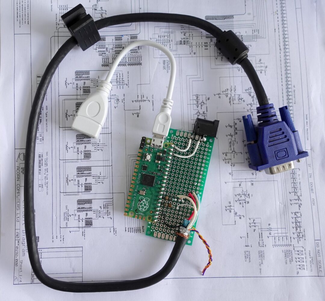
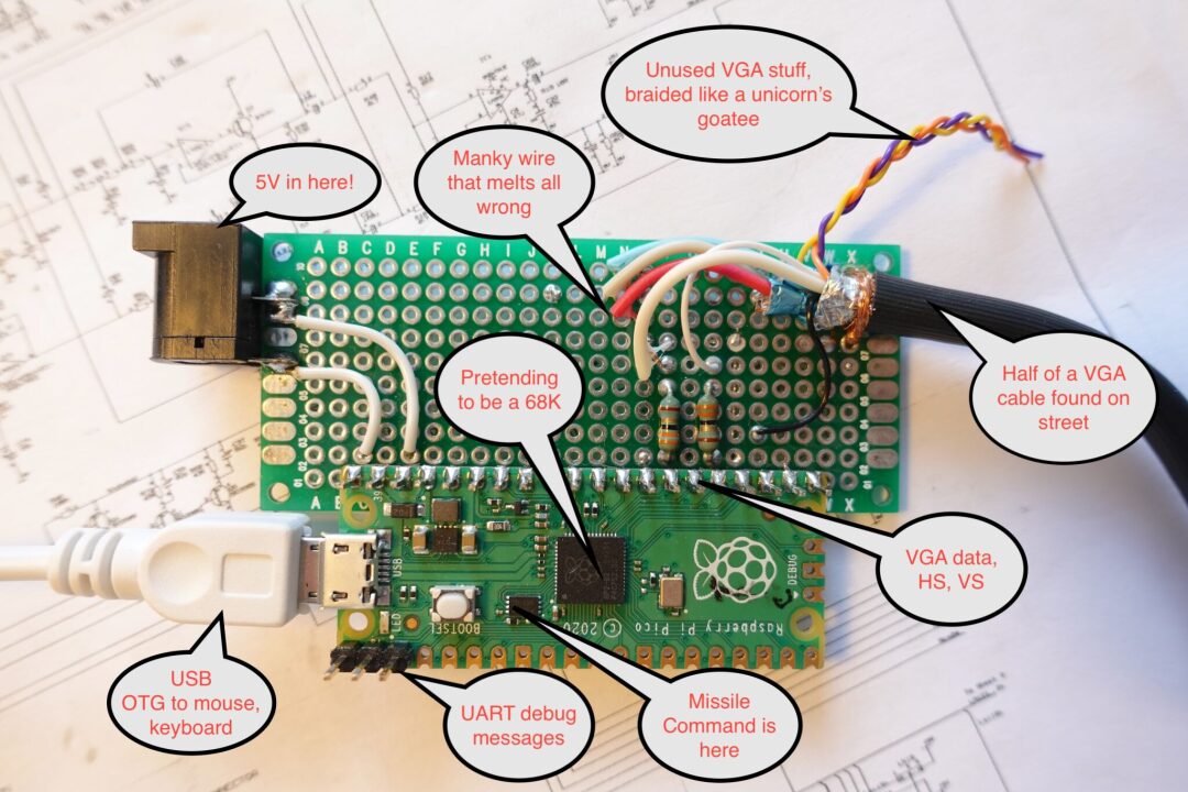
It is a system based on the Raspberry Pi RP2040 microcontroller (installed on the Pico board) that can drive monochrome VGA video and accept USB keyboard/mouse input, emulating the Macintosh 128K computer and its disk storage. The RAM capacity of the RP2040 is sufficient to accommodate both the Mac’s memory and the emulator’s memory. With some tricks, its speed can reach the performance of a real Macintosh, and the PIO module makes driving VGA video relatively straightforward. The basic Pico board’s 2MB flash memory is enough to hold the operating system and software disk images.
Here is the actual running situation of Pico MicroMac, ready for the future “paperless office”:
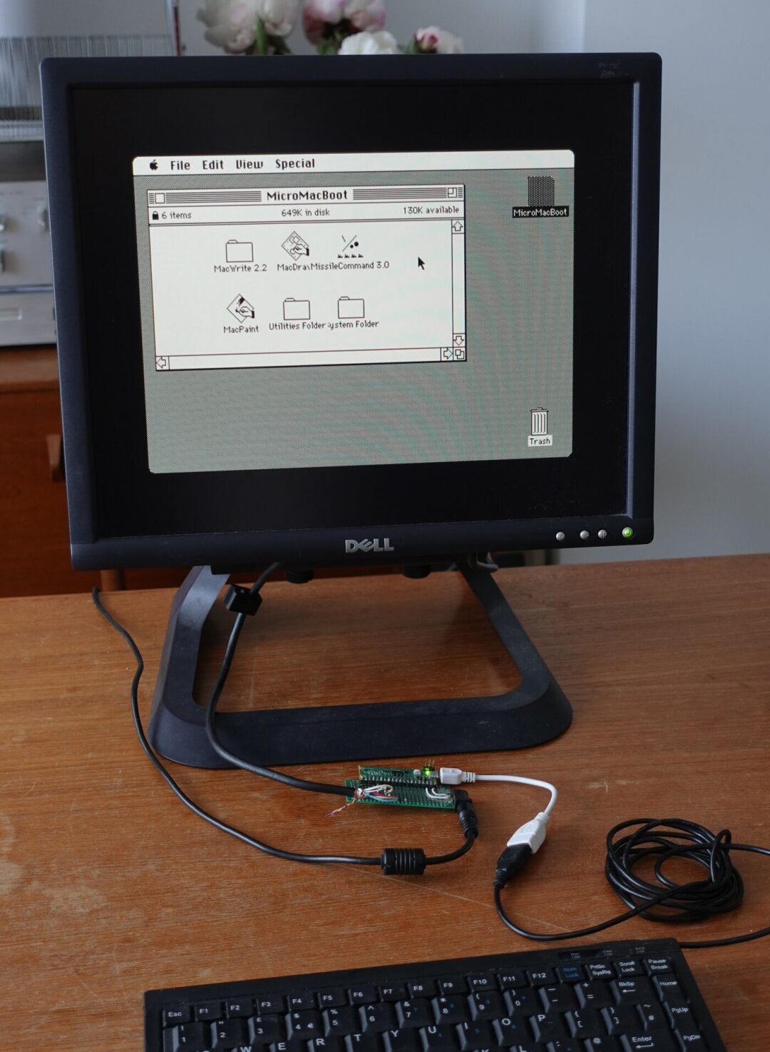
(The future Pico MicroMac RISC CISC workstation)
I hadn’t used a Mac 128K much before; I had only clicked around on a machine in a museum. But I knew it could run MacDraw, MacWrite, and MacPaint—these three applications were amazing for a 128K device: a basic WYSIWYG word processor with various fonts and a vector drawing software.
If you want to experience the early Macintosh system software and these great applications, one way is to visit https://infinitemac.org, which runs the Mini vMac emulator packaged to run in the browser (highly recommended, there are many interesting contents to play with).
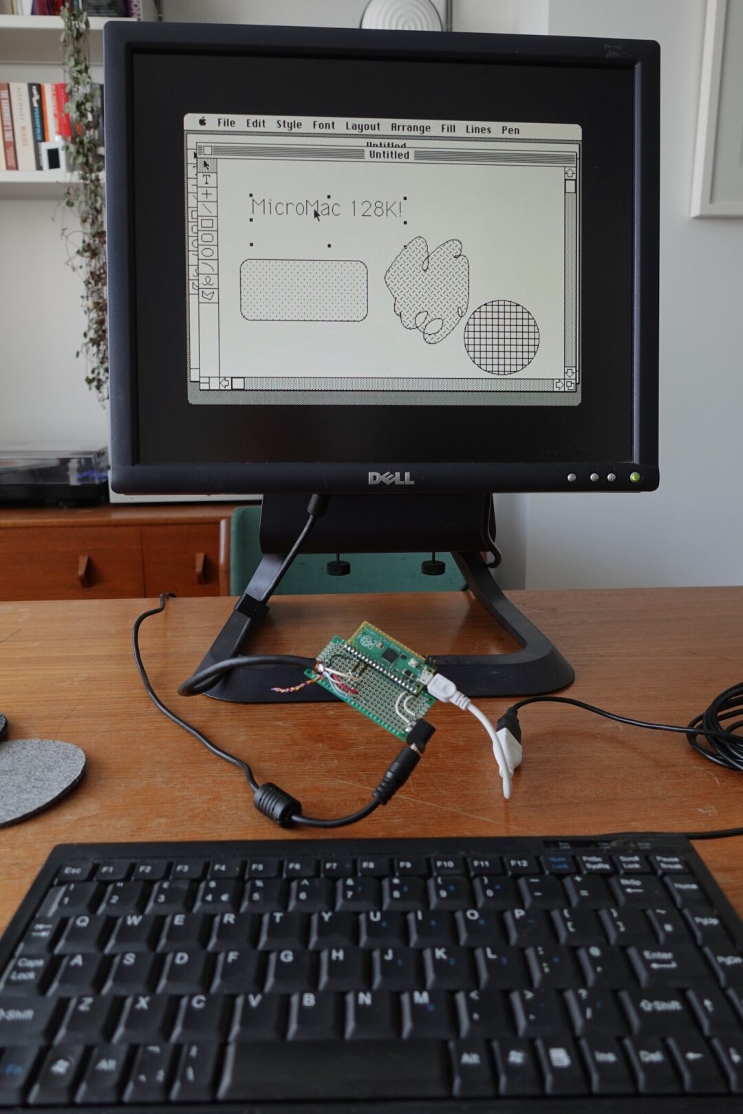
Spoiler alert: the MicroMac I developed can indeed run MacDraw, and it’s very fun to use it on the “emulated hardware”:
If you also want to build your own Pico-Mac, you can refer to the GitHub link (https://github.com/evansm7/pico-mac) for detailed production instructions.
My Development Journey Begins!
Upon reflection, I initially did not plan to create a Pico project; I was just vaguely interested in its feasibility, so I started tinkering with making a Mac 128K emulator on my regular computer.
Three Rules
For this project, I initially set a few simple rules:
-
Must do something interesting. Making some changes to make it run properly is also acceptable.
-
I like writing emulators, but I do not want to delve into learning and understanding 68K assembly language. I know many people love 68K, and it is indeed good, but I do not like to use it as a CPU. So initially, I planned to use an existing 68K interpreter made by others.
-
Similarly, I wanted to understand the internals of many operating systems, but early Mac system software was not on my consideration list. I just needed to get into the system, simulate the hardware, and start the operating system as a black box.
However, throughout the project, I often broke the above rules, sometimes two at a time, sometimes all of them.
Mac 128K
Such machines are generally very simple and fit the characteristics of the time. I started learning from the schematics and “Inside Macintosh,” which are PDF files covering various details of the original Mac hardware, memory mapping, mouse/keyboard, etc.
Hardware configuration of the Macintosh:
-
Motorola 68000 CPU running at approximately 8MHz;
-
Flat memory structure, decoding memory into different areas for memory-mapped I/O, connected to 6522 VIA, 8530 SCC, and IWM floppy disk controller (some address decoding is a bit complex).
-
Keyboard and mouse connected via VIA/SCC chip.
-
No external interrupt controller: the 68K has three IRQ lines corresponding to three IRQ sources (VIA, SCC, programmer switch/NMI).
-
No slots or expansion cards.
-
No DMA controller: a simple autonomous PAL state machine scans video and audio samples from DRAM. Video resolution is fixed at 512×342 1BPP.
-
The only storage device is the internal floppy disk drive (plus an external drive), driven by the IWM chip.
The first three Mac models are very similar:
-
Mac 128K and Mac 512K are the same device, just with different memory.
-
Mac Plus added a SCSI interface and an 800K floppy disk drive to the memory mapping, which is double-sided, while the original floppy drive was single-sided 400K.
-
The ROM of the Mac Plus also supports 128K/512K and is an upgraded version of the Macintosh 512Ke, where ‘e’ indicates additional ROM functionality.
The ROM of the Mac Plus supports the HD20 external hard drive and HFS file system, and Steve Chamberlin commented on its disassembly. This is the ROM I am going to use: I am making a Macintosh 128Ke.
Mac Emulator: umac
After about 8 minutes of research, I chose the Musashi 68K interpreter. It is written in C, has a simple interface, and provides a simple, out-of-the-box 68K system example that includes RAM, ROM, and some I/O. Musashi is suitable for embedding into larger projects: connecting memory read/write callbacks, an IRQ-triggering function, and calling execution in a loop, done.
I began to build an emulator around it, and eventually, this project became umac. The first half went quite smoothly:
1. Build a simple command-line application that loads the ROM image, allocates RAM, provides debug messages, assertions, and logging, and configures Musashi.
2. Add address decoding: guide CPU read/write operations to RAM or ROM. The “overlay” register allows the ROM to start at address 0x00000000, then jump to a high-address ROM image after setting the CPU exception vector—this affects address decoding. This is done through the VIA registers, so only part of that register is currently decoded.
3. At this point, the ROM starts running and accessing more non-existent VIA and SCC registers. So I added more address decoding and a framework to simulate these devices—making MMIO read/write operations simply marked out.
4. There are some special addresses for ROM access that will “miss” the recorded devices: there is a manufacturing test option that will probe for plugins, and then we will see the probe results for RAM size. The Mac Plus ROM is looking for up to 4MB of RAM. In the large area allocated for RAM, the actual smaller capacity of RAM is mirrored repeatedly, so the probe writes a special value at high addresses and at the point where it starts to wrap around.
5. Then initialize RAM and fill it with known patterns. This is an exciting moment because I can dump RAM and convert the area used for the video frame buffer into an image and see the “diagonal stripe” pattern used for RAM testing!
6. Not all device code likes to read all-zero values, so sometimes it is necessary to refer to disassembly and return 0xffffffff to push it further along. Our goal is to make it able to access the IWM chip, that is, to try loading the operating system.
7. After seeing some IWM accesses and returning random meaningless values, the first wonderful moment was the appearance of the “unknown disk” icon with a question mark—real graphics! The ROM is really doing something!
8. At this point, I had not yet implemented any IRQ, and I found that the ROM entered an infinite loop: it was calculating several Vsyncs to delay the blinking question mark. So I turned to a better VIA, which can provide callbacks for GPIO register read/write and IRQ handling. This also needs to connect to Musashi’s IRQ function.
This entire process largely motivated me to continue—remember rule one: while this was seen through manual memory dumps and ImageMagick conversions, it was still great.
IWM, 68K, and Disk Drivers
Actually, in the previous step, I already knew that IWM was a “fun” chip, but I was not very clear on the specific details, so I planned to figure it out as needed—thankfully, I delayed studying IWM until now. If I had read its “data sheet” (a vague register document) at the beginning of the project, I would have definitely given up right there.
IWM is indeed nice, but it is very low-level. Disk controllers of other contemporary machines, such as the WD1770, abstract the physical operations of the disk, so to some extent, you only need to toggle the registers to step the controller to track 17 and grab sector 3. But IWM does not work like that: first, the disk is constant linear speed, meaning the angular speed needs to be adjusted based on the current track; second, IWM only provides the CPU with a large amount of raw data read from the disk head (almost no decoding).
I spent a long time reading the disassembled code of the IWM driver in the ROM (breaking rules 1 and 2): the driver contains some sort of servo control loop that controls the disk motor by adjusting the PWM values sent to the DAC and comparing them to the reference values of the VIA timer to achieve dynamic rate matching to get the correct bit rate from the disk sector. I thought that once the track start point was found, the driver would stream the track data into memory, decode the symbols (more complex coding), and select the sectors of interest.
To be honest, I felt a bit defeated. I had thought that emulators like Basilisk II and Mini vMac had solved this problem somehow because they could simulate floppy disks—but in reality, they did not; they just avoided the problem altogether.
As for other emulators, they patched the ROM extensively: the ROM does not run unmodified. Some might say that while modifying the ROM means it is no longer perfect hardware emulation, so what? Well, I suspect they also followed rule 1 because I planned to do the same.
I studied how some Mac driver interfaces worked (sigh, still breaking rule 3), and understood how other emulators patched the ROM. They used custom semi-virtualized 68K drivers, overriding the IWM driver in the ROM to service requests from the block layer and route them to more convenient host-side code to manage those requests. Basilisk II used some custom 68K opcodes and a simple driver, while Mini vMac used a complex driver to perform “trap” accesses to custom memory regions. I reused the Basilisk II driver but converted it to access a custom area (which makes routing easier: just simulate another device). The driver callbacks to host/C execute, and some simplified Basilisk II code interprets requests and copies data to or from the buffers provided by the operating system. This way, I only needed to read blocks from one disk: no need for different formats (not even write support), no need for multiple drives, and no need for ejecting/replacing images.
Loading the first data block from the disk took longer than the total time spent on the first part. I was thinking about learning some 68K assembly again (again breaking rule 3…) but at this critical moment, I saw a Happy Mac icon indicating that the system software was starting to load.
At this point, my emulator was still a simple Linux command-line application with no user interface, no keyboard or mouse, and no video output. So I thought it was time to wrap it in an SDL2 frontend so that I could see the screen redraw in real-time. I added a 1Hz timer interrupt to the VIA, and it successfully booted!
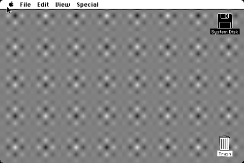
(First boot)
By the way, I tried to create a dual-target build for all embedded projects, one for rapid prototyping/debugging on the local host, replacing LCD with libSDL, which means I do not need to code on the MCU.
Next up was mouse support. The Macintosh internal diagram showed how it connected to the VIA and SCC. SCC is the second chip I did not like in this machine: it’s complex, the data sheet seems to intentionally hide information, annoy readers, and take revenge on the world. But it can execute various line coding schemes from the 1980s, relieving the CPU’s workload and is essential for supporting features like AppleTalk.
At this point, the prototype was almost complete: there was a working mouse, and I could build a new disk image with Missile Command using Mini vMac—less than 10KB and very fun.
Overall:
-
Video works
-
Can boot from disk
-
Mouse works, and Missile Command runs
Although there was no keyboard yet, most features were already implemented. It was time to start the second sub-project.
Hardware and RP2040
Unrelated to umac, I designed a circuit and firmware for two purposes:
(1) To display 512x342x1 video on VGA with the minimum number of components.
(2) To get the TinyUSB HID example working and integrated.
Specifically, this project was just to copy test images to the frame buffer and output keyboard/mouse via printf(), as a proof of concept. The video part was very interesting: although I had done some I2S audio PIO projects before, this time I wanted to output video signals and control Vsync and Hsync freely.
To test, I needed a circuit. The VGA interface requires video R, G, B signals to have a maximum voltage of 0.7V, as well as certain voltages for the sync signals (specific values vary).
The R, G, B signals have a 75Ω resistor to ground: after calculation, driving these three signals with a 100Ω resistor from a 3.3V GPIO is roughly feasible.
The day I started soldering, I needed a VGA interface. Although I had a DB15 connector on hand, I wanted to use it for another project, and cutting the VGA cable didn’t seem appropriate. While taking a walk after lunch, I accidentally found some cables on the street, one of which was a VGA cable—although rusty, it had a certain casual beauty.
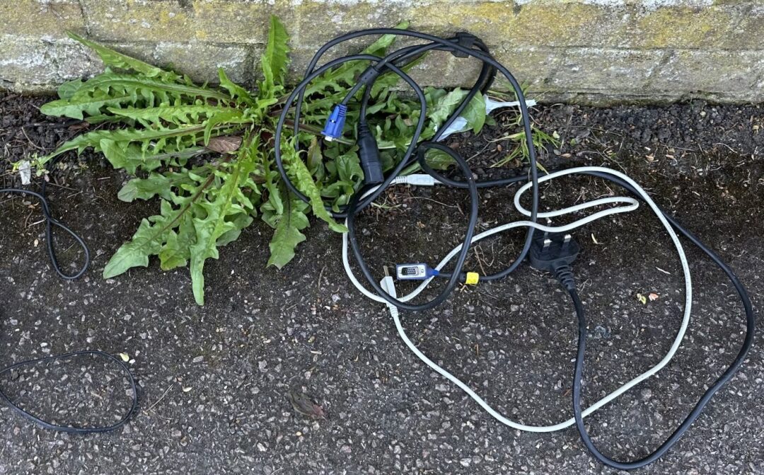
(Free VGA cable)
The VGA PIO part was very interesting. Ultimately, the PIO dynamically read configuration information to control Hsync width, display position, etc., and then used some DMA tricks to scan out the configuration information with the frame buffer data. By using the correct bit shift direction and the byte swap option on the RP2040 DMA, it could directly output the big-endian Mac frame buffer without copying or formatting conversion on the CPU side.
However, I rewrote the video part three times in total:
(1) The first version had two DMA channels writing to the PIO TX FIFO. The first transferred configuration information, then triggered the second transfer of video data, and then triggered an IRQ. Then, the IRQ handler would select the new frame buffer address to read from for a short time and reprogram the DMA. This method worked fine but was very sensitive to other activities in the system. An obvious solution was that any latency-sensitive IRQ handler must have the __not_in_flash_func() attribute to avoid RAM exhaustion. But even so, the design did not leave much time to reconfigure the DMA: when moving the mouse quickly, random flickering and blanking would occur.
(3) The second version used double buffering, aiming to simplify the IRQ handler’s work: quickly inserting pre-prepared DMA configurations, then calculating the next buffer to use at the critical moment. This method worked much better, but still had some faults under high load. Strangely, it would sometimes go completely blank and require a reset, which confused me for a while. Eventually, I printed the FDEBUG register of the PIO FIFO, trying to discover errors in real-time. I saw the TXOVER overflow flag set, but that should not have been possible: the FIFO pulls data from the DMA as needed, with DMA requests and credit-based flow control… oh wait, if credits get confused or duplicated, excessive transfers could occur, leading to overflow on the receiving end.
I overlooked a detail rule in the RP2040 DMA documentation: “Multiple channels should not connect to the same DREQ.””>
(3) Therefore, the third version… did not violate this rule but became more complex:
-
One DMA channel transfers data to the PIO TX FIFO
-
The second channel is responsible for setting the first channel, sending data from the configuration data buffer
-
The third channel is responsible for setting the first channel, sending data from the video data buffer
-
The setup of the first channel triggers the corresponding “next reprogram me” channel
In addition to not experiencing locking or video corruption, another benefit is that an Hsync IRQ will be triggered during the video line scan, greatly shortening the time limit for reconfiguring the DMA. I also wanted to improve this further (adding another DMA channel) so that each line transfer would not require an IRQ, as the current IRQ overhead accounts for about 1% of the CPU time.
So now we have a platform and firmware framework that can embed umac, supporting HID input and video output. The hardware part is complete, and now it is up to the software team.
Back to the Emulator Development Work
Looking at the local umac binary, I found that some issues needed to be resolved to run it on the Pico:
-
The Musashi runtime builds a huge opcode decoding jump table in RAM. This table never changes and is not modified at runtime. I added a Musashi build-time generator so that this table can be set as const (to be stored in flash).
-
The disassembler takes up a lot of space and is not used on the Pico, so a build version without the disassembler can be made.
-
Musashi uses a lot of large lookup tables to accurately calculate the execution cycles of each instruction. While this is useful for some game consoles, it is not important for the Mac, so I removed these lookup tables.
pico-mac began to take shape, with ROM and disk images stored in flash, and it was now possible to build and run it on the Pico! Just be careful not to fill up RAM; the RAM usage is still quite good. The emulator and HID code together use about 35-40KB of the Mac 128KB RAM area, leaving over 95KB available.
This was just the right time to add keyboard support to umac. The Mac keyboard connects through the “shift register” serial interface of the VIA, which is a basic synchronous serial interface. Although logically simple, it was always ignored when I initially tried to respond to the ROM’s “initialization” command. The disassembly of the ROM came in handy: while reading the keyboard startup code, if the response byte appears too early after the request is sent, it can lead to a race condition in interrupt acknowledgment. Therefore, I inserted a delay after the request is sent, delaying the response to a later poll, and then I only needed to map the key codes.
With keyboard support, the final hurdle for MacWrite was reached:
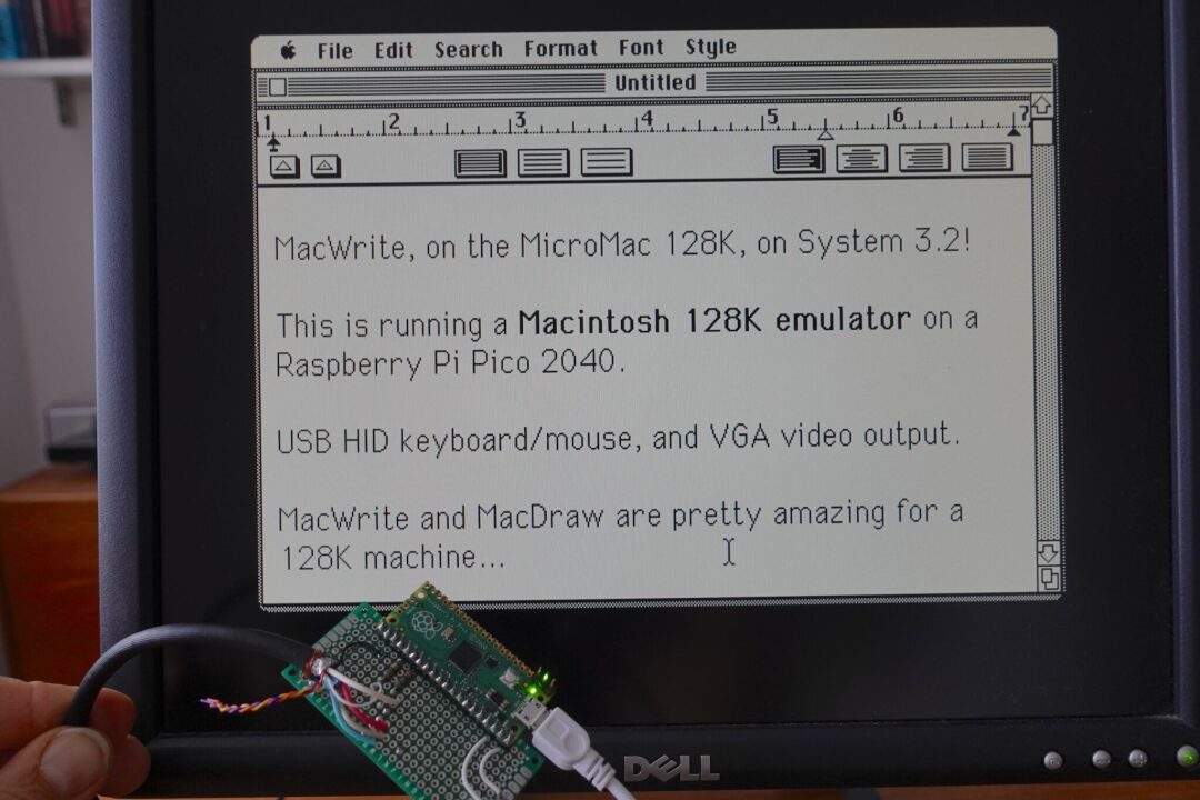
However, there was one problem: its performance was totally unacceptable, running super slow. I added a 1Hz instruction count dump and found it executed only about 300 KIPS (thousand instructions) per second.
The 68000 CPU is not great in IPC. While some instructions can execute in 4 cycles, accessing memory with those complex addressing modes takes many cycles. Of course, I am not an expert, but I think it is not unreasonable to set a target of about 1 MIPS (million instructions) for the 68000 at around 8MHz, just needing a 3x improvement.
Performance
I never said I wouldn’t cheat: let’s boost the Pico’s operating frequency from 125MHz to 250MHz. It did improve a bit, but not to double; I remember it only improved by about 30%.
Musashi has many configurable options. My first goal was to make the main loop (from the disassembly/compiler backend perspective) smaller: the Mac does not report bus errors, so the register does not need to be copy expanded. Opcodes are always fetched from 16-bit boundaries, so no alignment checks are needed, and half-word loads can be used (instead of merging two bytes into a half-word).
For the Cortex-M0+/armv6m ISA, better code can be achieved by rearranging the CPU context structure fields for immediate offset access. Confusingly, the CPU type is dynamically variable, leading to a lot of indirect operations at runtime.
It looked much better, maybe a 2x improvement, but still not enough. Missile Command was still choppy, and the mouse remained unresponsive! Next, I implemented some more aggressive optimizations: I removed address alignment checks, as unaligned access would not occur in such a constrained environment.
However, the real optimization came from another little trick mentioned below.
RP2040 Memory Access
The RP2040 has fast RAM that uses a multi-row design, allowing multiple users (like two CPUs and DMA) to access it in a single cycle. By default, most code runs via external QSPI flash’s XIP, which typically runs at the core clock speed (default 125MHz), but the latency for randomly reading a word is about 20 cycles. To shorten this latency, the RP2040 is equipped with a simple 16KB cache, but if the code size is large, it is easier to trigger QSPI reads when calling functions. When overclocked to 250MHz, QSPI cannot reach such a high frequency, so it stays at 125MHz. This means that when the cache misses, the 20-cycle latency of QSPI becomes 40 CPU cycles.
The problem here is that Musashi generates a lot of code at build time, with a function for every 1968 opcodes, plus a 256KB opcode jump table. Even if the internal execution loop is very efficient, opcode dispatch and function calls may miss in the flash cache. If we want to achieve 1 MIPS based on 200 MIPS, these latencies will accumulate.
In the face of this, we can use the __not_in_flash_func() attribute to copy specified functions into RAM to ensure fast execution. At the very least, the main loop and memory access functions need this attribute, as every instruction needs to access an opcode and is likely to read and write RAM.
This optimization improved performance by several percentage points.
Next, I tried to optimize whole classes of opcodes: moves are frequent, branches are also frequent, so putting them in RAM can indeed improve performance, but RAM quickly runs out, and there is still a gap to the target of 1 MIPS.
Remember I said RISC architecture would change everything?
Which of the 1968 68K opcodes that we want to accelerate are the most commonly used? By adding a 64K counter table to umac, booting the Mac and running some key applications (actually playing Missile Command for a while), we can get a statistical overview of dynamic instruction usage. The result showed that the 100 most commonly used opcodes (accounting for 5% of the total) accounted for 89% of the execution counts, while the 200 most commonly used opcodes accounted for 98% of the execution counts.
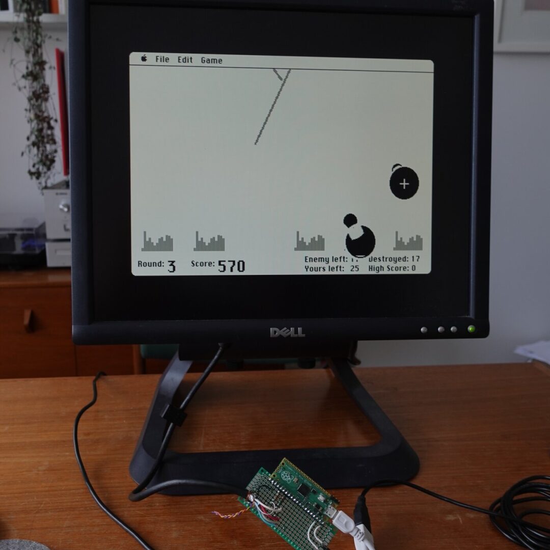
Based on this statistical result, umac processes the code automatically generated by Musashi after building and attaches the __not_in_flash_func() attribute to the 200 most commonly used functions. This only increased RAM usage by 17KB (remaining 95KB), while performance improved to about 1.4 MIPS!
Finally, we can enjoy the dark theme of Missile Command smoothly:
What About MacPaint?
Everyone loves MacPaint, but you will find I have been avoiding it because:

It cannot run on the Mac 128Ke because the RAM used by the Mac Plus ROM is more than the original: I saw a discussion about “Mac 256K” on 68kMLA, and it is very likely that the Mac 128K was actually a Mac 256K in the lab (it may have even been intended to be 256K but cut costs before release).
At that time, I was wondering whether the Mac ROM/OS had to be a power of 2? If not, then I still have 95K of free memory; could I create a “Mac 200K” and run MacPaint? So I tried a local hack that could modify the ROM based on the given memory size, updating its global memTop variable. The results were good; I also conducted boot tests with 256K, 208K, and 192K. However, there were some issues to resolve: if the memory size is not a power of 2, the ROM memtest will fail, while skipping this test leads to other issues. These problems can all be solved, but certain boot processes will access areas beyond the end of RAM. Furthermore, powers of 2 restrict RAM access to valid buffers through simple address masking, which 192K cannot do.
Unfortunately, when I tested MacPaint, it still would not run because it needs to write temporary files to a read-only boot volume. This completely violates rule 1, so for now, we will still stick with 128KB. However, a 256K MicroMac is entirely feasible, requiring just a microcontroller with 300KB of memory to achieve it.