
0. Introduction

For sensor selection, many beginners and even engineers are not very clear about the differences between various price ranges and devices. Here, the author wants to provide some suggestions based on personal experience and online resources, as well as how to use these devices.

1. Cameras

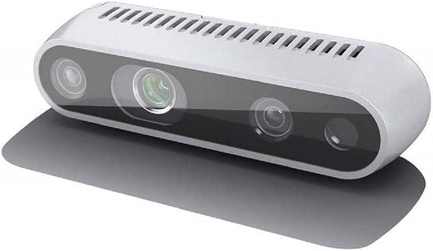
1.1 USB Camera (Amateur & Consumer)
A USB camera is a security camera that uses a USB interface, plug-and-play, foolproof operation, no capture card required, no power supply needed, and no need to disassemble the case, supporting laptops. Compared to traditional surveillance cameras, it is more cost-effective and allows for remote viewing over the network. Convenient and practical, with simple operation.
-
Pros: Very easy to integrate.
-
Pros: Can perform many offline image tasks (exposure control, frame rate, etc.).
-
Pros: Provides input/interruption functionality, which can save computation time in applications (e.g., interrupting on a new frame).
-
Cons: Since the USB bus uses CPU time, if 100% CPU is used, it will affect your application.
-
Cons: Not optimal for using hardware vision pipelines (hardware encoders, etc.).
-
Pros: Can work over long distances (up to USB standards).
-
Pros: Can support larger image sensors (1 inch or larger for better image quality and less noise).
1.2 MIPI CSI Bus Camera (Consumer)
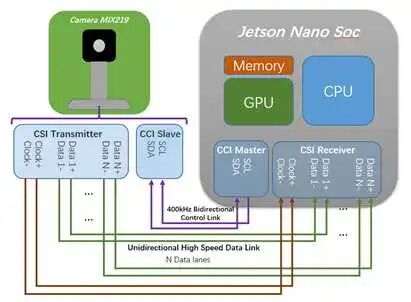
The CSI-2 interface specification was released by the MIPI (Mobile Industry Processor Interface) Alliance in 2005 regarding camera serial interfaces. The MIPI Alliance was established in 2003 by companies such as ARM, Nokia, ST, and TI, with the aim of standardizing internal interfaces in mobile phones, such as camera, display, RF/baseband interfaces, etc., to reduce design complexity and increase design flexibility. The MIPI Alliance has different WorkGroups that define a series of internal interface standards for mobile phones, such as camera interface CSI, display interface DSI, RF interface DigRF, microphone/speaker interface SLIMbus, etc.
-
Pros: Optimized based on CPU and memory usage for image processing and storage.
-
Pros: Can fully utilize the hardware vision pipeline.
-
Cons: Supports short distances (usually no more than 10cm). Unless you use serialization systems (GMSL, FPD Link, COAXPress, Ambarella), but these systems are currently immature and require customization.
-
Cons: Usually has small sensors like mobile camera modules, or you have to spend more money to customize. Use hardware denoising in TX1/2 to reduce extra noise from small sensors.
-
Pros: Can perform low-level access and control of sensors/cameras.
1.3 Ethernet Camera (Robotics & Automotive)
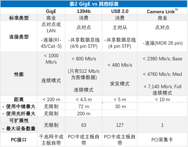
The American Automation Imaging Association (AIA) introduced the GigE Vision standard, which is developed based on the Gigabit Ethernet communication protocol, enabling fast long-distance image transmission through existing Ethernet cables, capable of real-time, high-bandwidth transmission of large images at a rate of 125MB/s over a distance of up to 100 meters.
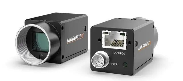
GigE industrial cameras can unify the protocols of almost all industrial cameras in machine vision products, while also allowing other organizations to develop compatible software and hardware based on it. Currently, many products support the GigE Vision standard.
1.4 GMSL Camera (Automotive)
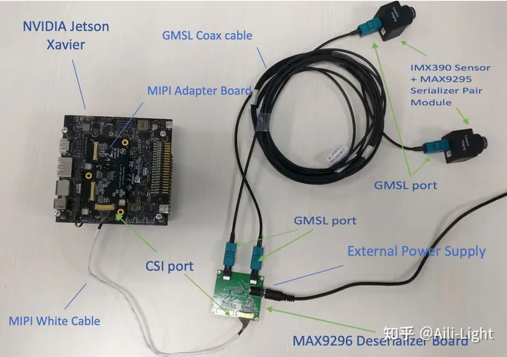
The LVDS data transmission interface mainly has two protocols: GMSL and FPD Link, which are widely used in automotive video transmission, especially in the link between cameras and processors, achieving a total link length of 15m through STP or coaxial cables.
GMSL is a high-speed serial interface introduced by Maxim, suitable for the transmission of video, audio, and control signals, with distances of up to 15m or longer when using 50Ω coaxial cables or 100Ω shielded twisted pair (STP) cables.
Taking ADAS cameras as an example, this is also a major application area for GMSL. Generally, cameras not only send captured image data externally but also send frame synchronization signals, line synchronization signals, pixel clock information, and power supply, etc. It consists of many signal lines forming a parallel bus, which is not advantageous in high-speed data transmission. Therefore, we need to combine these parallel signals into serial signals and transmit them at a higher frequency.
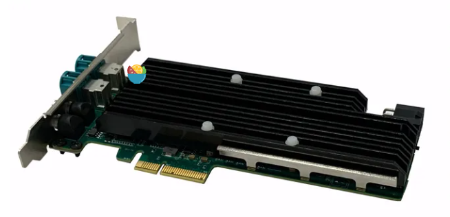
The PCIe capture card (Figure 7) is specifically designed for PC computers/industrial computers to connect GMSL cameras. PCIe capture cards feature high bandwidth and multi-channel capabilities, with good universality and high real-time performance, widely used in the research and data collection of autonomous driving.
As shown in Table 2, the data transmission bandwidth for 1M (1 million pixels) – 8M (8 million pixels) cameras ranges from 655Mbps to 4.4Gbps. In terms of bandwidth limitations, USB3.0 can only support up to 2M, Ethernet up to 1M, and only PCIe can meet all transmission requirements.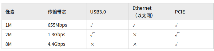
1.5 FPD Link (Automotive)
FPD-Link III serial bus solution supports high-speed video data transmission and bidirectional control communication through a single differential link, achieving full-duplex control. Integrating video data and control through a single differential pair can reduce interconnect size and weight, eliminate deviation issues, and simplify system design.FPD Link is a serial bus solution from TI. Like GMSL, it can use 50Ω coaxial cables or 100Ω shielded twisted pair (STP) cables for low-latency transmission of uncompressed video and control data.
With FPD-Link™ serializers and deserializers, the design and transmission of high-resolution signals for various video interfaces in automotive systems (including cameras for advanced driver assistance systems (ADAS) and infotainment system displays) are simplified. Our FPD-Link camera serializers/deserializers support the transmission of uncompressed video, control signals, and power through a single low-latency cable. Our FPD-Link display serializers/deserializers support full 1080p, 2k, and 3k HD displays and device-level HDCP keys, while also providing adaptive equalization to compensate for cable aging and temperature variations.
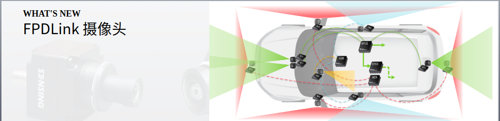
For a detailed history of automotive development, you can refer to this article on automotive electronic data transmission protocols: CAN, CAN FD, A²B, Ethernet100Base-T1 & Ethernet1000Base-T1, FPD-LINK, GMSL terminology summary.

2. IMU

2.1 Inertial Measurement Unit
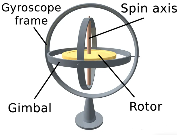
An Inertial Measurement Unit (IMU) is a device that measures the three-axis attitude angles and acceleration of an object. An IMU typically includes gyroscopes, accelerometers, and sometimes magnetometers. Gyroscopes measure the angles/angular velocities in three axes, accelerometers measure the acceleration in three axes, and magnetometers provide magnetic field orientation information.
2.2 IMU Classification
For IMUs, the technical barriers are high and the market share is highly concentrated, mainly divided into three types: laser, fiber optic, and MEMS.
2.2.1 Ring Laser Gyro (RLG) IMU – Ring Laser Gyroscope (Automotive + Usable as Truth)
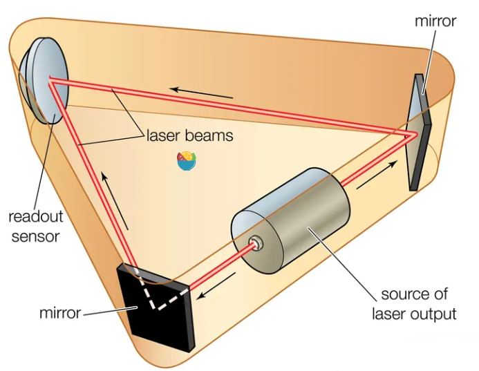
In 1913, French scientist George Sagnac discovered that when a light beam travels in a circular medium channel, if the circular channel itself has a rotational angular velocity, the time required for the light to travel in the direction of the channel’s rotation is longer than the time required to travel in the opposite direction. The two types of gyroscopes utilizing the Sagnac effect are the ring laser gyroscope and the fiber optic gyroscope. These two methods produce radar with higher accuracy, but they are also more expensive.
The ring laser gyroscope IMU uses a ring laser and fiber optic sensors to measure angular velocity. It is based on the principle of optical rotation, calculating angular velocity by measuring the phase difference of the laser beam along the circular path.
2.2.2 Fiber Optic IMU – Fiber Optic Gyroscope (Automotive + Usable as Truth)
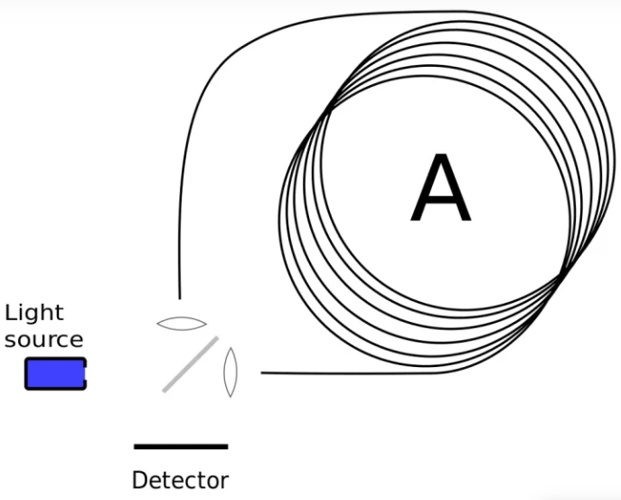
Fiber optic IMUs use fiber optic sensors to measure the acceleration and angular velocity of an object. It is based on the interference principle of fiber optics, calculating motion parameters by measuring the optical path difference in the fiber. This design is more ingenious, directly using fiber optics to create a circular medium channel. Compared to the former, it does not require precision processing of optical mirrors or strict sealing of optical cavities, and fundamentally avoids laser locking issues.
2.2.3 MEMS IMU (Consumer – Automotive)
MEMS (Micro-Electro-Mechanical Systems) is a microelectromechanical system that contains tiny mechanical structures and electronic components. MEMS IMUs are inertial sensors based on MEMS technology, used to measure acceleration and angular velocity.
The working principle of MEMS IMUs is based on the micro-mechanical structures and electronic sensors in microelectromechanical systems. An alternating voltage of 14 kHz causes a flexible oscillator to resonate periodically in the direction of the red arrow in the diagram. When the detection unit rotates along the blue axis, the flexing oscillator in linear motion experiences Coriolis force, resulting in an oscillation of 14 kHz, which is detected by capacitive sensors to obtain the Coriolis force and thus the angular velocity of rotation.
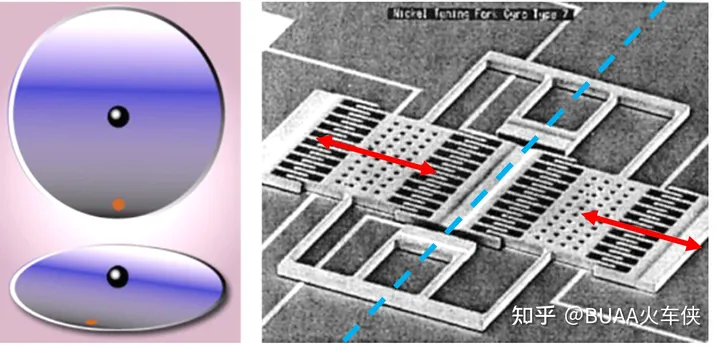
Mainly includes the following aspects:
-
Acceleration Measurement: MEMS IMUs use tiny mass blocks (mass) and spring systems in micro-mechanical structures to measure acceleration. When the IMU experiences acceleration, the mass block is displaced due to inertial force, and this displacement is converted into an electrical signal through electronic sensors such as capacitive, resistive, or piezoelectric effects, thus measuring the magnitude and direction of acceleration.
-
Angular Velocity Measurement: MEMS IMUs use tiny gyroscopes in micro-mechanical structures to measure angular velocity. Gyroscopes can sense angular velocity through inertial or rotational forces. Typically, MEMS gyroscopes measure changes in angular velocity through tiny vibrating structures, piezoelectric effects, or optical sensors.
-
Signal Processing and Output: The electronic components of MEMS IMUs are responsible for converting mechanical motion into electrical signals, processing and amplifying these signals. These processing circuits can convert tiny mechanical movements into measurable and usable electrical signals. Ultimately, the IMU outputs the measured acceleration and angular velocity data to the system for further applications.
2.3 Major Manufacturers
MEMS-IMUs are mainly dominated by overseas companies such as Honeywell, ADI, and Northrop Grumman, which account for 55% of the global market; domestically, companies are in a catch-up phase, with Minghao Sensor, Xindong Lianke, and Meitai Technology as representatives, while automotive IMU modules are mainly represented by Huayi and Daoyuan.
First Tier: Suzhou Goodrich (Minghao Sensor), Xindong Lianke (listed this morning), Huayi Technology (IMU designated for multiple automotive companies), pure MEMS-IMU.
Second Tier: StarNet, Huace Navigation, Beidou Navigation, Ligong Navigation, etc., mainly focused on laser and fiber optic types, with fewer MEMS, and their main business is strongly related to military or has impacts on specific customer expansions.
Third Tier: Minxin Co., Ltd. (only accelerometers), Saiwei Electronics, etc.
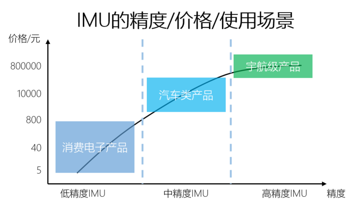
Some commonly used combination navigation selections can refer to this article: Combination Navigation Selection.

3. LiDAR

The main content has been detailed in the book “Practical Guide to Drone Programming from ROS1 to ROS2”. Here is a brief description: 3D LiDAR mainly includes
3.1 Mechanical Scanning LiDAR (Consumer)
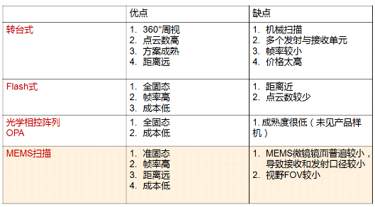
This 3D LiDAR uses multiple laser beams emitted simultaneously and directs these beams through a rotating scanner or optical components. They can simultaneously acquire point cloud data from multiple angles to improve the efficiency and accuracy of 3D perception. Rotating multi-beam LiDAR typically has higher resolution and longer measurement distances but is relatively complex and expensive.
3.2 Solid-State LiDAR – Flash (Consumer – Automotive)
Flash LiDAR, also known as panoramic LiDAR, emits a large number of laser beams in a single shot. They use an array of photodetectors to record the reflection time of the laser beams and calculate distances by measuring the time difference. Flash LiDAR has high speed, panoramic scanning, and short measurement times, but typically has lower resolution and shorter measurement distances.
Flash LiDAR is equivalent to using a flash to emit lasers and using detectors to receive signals. Since it is fully solid-state, it is much smaller, but the problem is that it can be overexposed at close range and cannot measure at long distances (due to insufficient capability), so currently, flash LiDAR typically measures distances within 50 meters.
3.3 OPA LiDAR (Consumer – Automotive)
OPA LiDAR uses Optical Phased Array technology to direct and control laser beams. They use optical components and phase modulators to adjust the phase and direction of the laser beams and calculate distances by measuring time differences. OPA LiDAR has high speed, panoramic scanning, and long measurement distances, while also having high resolution and flexibility.
However, OPA (Optical Phased Array), similar to millimeter-wave radar using RF signals, focuses using phased arrays to scan. It is implemented on the scale of optical wavelengths, making it more challenging than millimeter-wave technology, and some companies are working on solutions.
3.4 MEMS LiDAR (Consumer – Automotive)
MEMS LiDAR uses Micro-Electro-Mechanical Systems (MEMS) technology to achieve miniaturized laser emitters and detectors. They use tiny vibrating mirrors or arrays to direct laser beams and calculate distances by measuring time differences. MEMS LiDAR has small size, low power consumption, and lower costs, but typically has shorter measurement distances and lower resolution.
MEMS LiDAR can achieve 64 lines by using MEMS micro-mirrors to scan the pulses emitted by a single laser into a grid that can form 64 lines, making it very easy to achieve high resolution and very compact size. In the future, the cost of MEMS LiDAR is expected to be controlled within a thousand RMB.
 Source: GuyuejuDisclaimer: Some content is sourced from the internet for educational and communication purposes. The copyright of the article belongs to the original author. If there are any issues, please contact for removal.