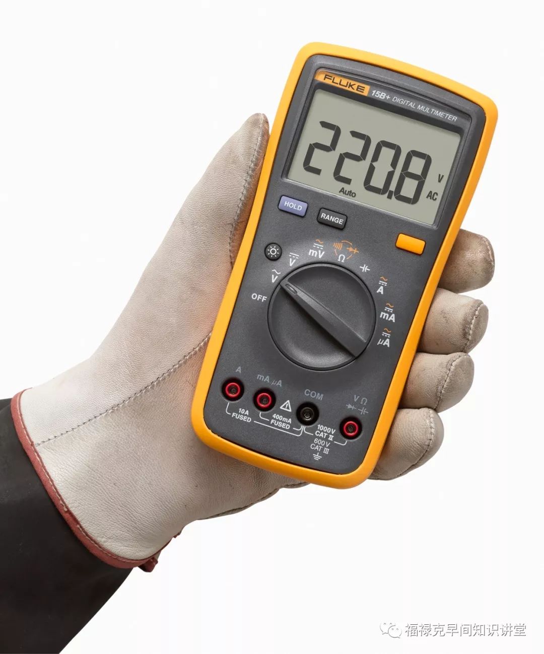
Chapter 25: Answers to Common Questions About Digital Multimeters
The digital multimeter is the most basic and indispensable tool for electrical engineers and technicians. In the field, due to various factors such as testing environment, electrical atmosphere, tested equipment, and signal type, users often encounter significant deviations in test results or even damage to the multimeter.

Today, Fluke brings you practical insights to help you understand the common problems encountered during actual testing with multimeters and their solutions.
1. Why does the multimeter display fluctuating values when turned on?
When the multimeter is set to voltage or current mode, it may display certain readings before any testing is done. This is mainly due to the influence of the external electrical environment, including electromagnetic fields and static electricity in the air.
However, when the red and black probes are shorted, the multimeter should read 0 or close to 0, indicating that normal testing can proceed. During actual testing, the multimeter is connected in parallel or series in the circuit, and the probes are effectively shorted through the tested circuit, which helps eliminate external interference and ensures the accuracy of the test results.
2. How to quickly check if the multimeter fuse is good or bad?
As we know, the multimeter has a built-in fuse in the current mode to ensure safety during current testing. If the circuit current exceeds the limit or poses a danger, the fuse will blow to protect the instrument and the operator.
To quickly check if the fuse is faulty, you can use the following method:
Set the multimeter to the “Ω” mode and use only one probe. Insert the probe into the Ω socket and touch the tips into the “A” and “mA/uA” sockets. If there is a reading, the fuse is good (the reading for the “A” socket should be 0-0.5Ω, and for the “mA/uA” socket, it should be around 10KΩ). If it shows “OL”, it indicates the fuse is blown.

3. What is the internal resistance of the voltage range in the multimeter?
All digital multimeters should have an internal resistance in the voltage range that is much greater than the impedance of the tested circuit, theoretically infinite.
During actual voltage testing, the internal resistance of the multimeter and the external circuit share the voltage. When the internal resistance is infinite, it ensures that the entire tested voltage is dropped across the multimeter’s internal resistance, resulting in more accurate readings.
Therefore, Fluke’s multimeter has an internal resistance of 10MΩ in both AC and DC voltage ranges, ensuring absolute accuracy of the test data.
4. Why are there large errors when testing different types of signals?
Digital multimeters are divided into average response and true RMS types based on their testing principles. This is mainly for testing different types of signals. When testing standard AC power and low-voltage distribution devices, the signals are usually standard sine waves, and a multimeter using average response can meet the testing requirements.
However, when testing nonlinear loads, due to environmental factors and three-phase imbalance, signals can often be distorted, such as voltage surges/dips and harmonics. These types of signals require a true RMS multimeter for accurate testing.
Additionally, for variable frequency/inverter devices, due to significant signal variations, such as converting DC to AC and vice versa, the entire process involves frequency and true value changes. To test the true values, a low-pass filter function is needed.
Therefore, during the initial selection, it is essential to understand the actual testing requirements and provide targeted or reasonable solutions to ensure the reliability and authenticity of the test results.
For more details, please contact:
Official Hotline: 4008103435
Fluke Official Website: www.fluke.com.cn