With the booming development of automotive electronics and industrial automation, the number of devices and data volume on the CAN bus has greatly increased, posing significant challenges to the CAN bus. To meet the higher bandwidth and data throughput requirements, CAN FD (CAN with Flexible Data-Rate) was born. So what exactly are the differences between CAN FD and traditional CAN? What are the differences in data transmission and real-time performance?
Generally, there are the following three reasons for transitioning from traditional CAN to CAN FD:
CAN FD increases the bit rate while providing shorter CAN frames
– Shorter delay time.
– Better real-time performance
– Higher bandwidth
CAN FD can accommodate more data from 8 to 64 bytes within a CAN frame
– Relatively less system overhead = better data throughput
– Simpler and more efficient software when sending larger data objects
CAN FD has a higher performance CRC algorithm
– Reduces the risk of undetected errors
Since CAN FD is a product of the increasing data load on the CAN bus reaching its limits, this article aims to compare CAN FD with traditional CAN while detailing CAN FD.
Data frame format of CAN FD vs Traditional CAN
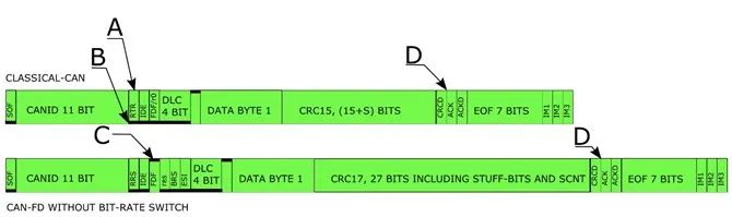
Figure 1 compares traditional CAN frames (top) and CAN FD frames (bottom). Both frames are single-byte data, and in this example, the CAN FD frame does not increase the bit rate. It can be seen that both frames are identical from the frame start (SOF) bit to the entire 11 arbitration bits. After arbitration, traditional CAN (marked as A) has a remote transmission request bit (RTR bit), while the CAN FD frame has a remote request replacement bit (RRS bit). For data frames, this bit is always dominant (0) in both frame formats. The dominant bit, usually defined as logical 0 and 0 volts, is represented by a thicker black line at the bottom (marked as B).
Figure 1 Comparison of Traditional CAN and CAN FD Frames
After the remote transmission request bit (RTR bit), the next bit is the dominant identifier extension bit (IDE bit), indicating that this frame uses the 11-bit arbitration basic frame format. Note that this article will not cover the EF extended frame format (EFEFF) using 29-bit arbitration.
The IDE bit is followed by the r0 bit (reserved bit), which is always dominant in the traditional CAN frame format. In the CAN FD frame format, this bit is recessive (see C), indicating that this frame is not a traditional CAN frame but a reserved format CAN frame, now referred to as CAN FD (CAN Flexible Data-rate). In other words, this bit indicates whether the CAN frame is a traditional CAN frame or a CAN FD frame. Since the release of the ISO11898-1 standard, this bit has been known as the FDF bit (Flexible Data Format bit), replacing the name r0 bit from earlier versions of the ISO11898-1 standard. Any reference to the r0 bit in previous documentation or datasheets is the same as the FDF bit in the ISO11898-1 version released in 2015.
Additional Bits in CAN FD
The FDF bit/r0 bit (which we will now refer to as the FDF bit) is followed by the reserved bit (res) for the FD format and the data length code bit (DLC) for traditional CAN format.In other words, all traditional CAN controllers generated according to the previous ISO11898-1 standard will misinterpret CAN FD frames, leading to erroneous frames from traditional CAN controllers.After the cyclic redundancy check (CRC) delimiter (marked as D in Figure 1), traditional CAN and CAN FD are consistent in their bit patterns.In other words, before the next frame begins, both traditional and FD formats use the same ending pattern.
All CAN FD controllers can handle a mix of traditional CAN frames and CAN FD frames. This means it is feasible to start using CAN FD controllers in existing systems while still using traditional CAN format controllers. Once all older traditional CAN controllers are replaced by CAN FD controllers, traditional CAN frames can be mixed with CAN FD frames or only one type can be used.
After the FDF bit in the CAN FD frame is the reserved bit. Setting this bit to recessive indicates future protocols, similar to how the FDF bit indicates the transition from traditional CAN to CAN FD format. Future protocols have yet to be defined. It is worth noting that the r0/FDF bit in traditional CAN format took 25 years to indicate the CAN FD format.
After the reserved bit is the BRS bit (bit rate switch). This additional bit allows CAN FD frames to be sent in two different formats. If the BRS bit is sent as dominant, all bits will be sent at the same bit rate used in the arbitration shown in Figure 1. If the BRS bit is recessive, the frame format after this bit will use a higher bit rate until and including the CRC delimiter.
After the BRS bit is the ESI bit (Error State Indicator), usually sent as dominant by the master. If the sending node of the CAN FD frame becomes error-passive, this bit will be sent as recessive, indicating that the sending node has significant communication issues. It is currently unclear how this bit will be used in broader applications, but it has already been adopted by automakers as needed.
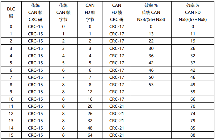
Following these 3 new bits (reserved bit, BRS bit, and ESI bit) are 4 DLC bits indicating the number of data bytes in the CAN frame. Table 1 shows how these 4 bits are used to indicate the number of data bytes in the CAN frame. Traditional CAN frames can accommodate a maximum of 8 bytes of data. From the table, it can be seen that exceeding 8 bytes can send a DLC code, but only 8 bytes of data will be placed in the sent CAN frame. A close examination of the table reveals that DLCs from 9 to 15 differ in the CAN FD format. Any number of bytes from 9 to 63 requires 6 bits of DLC, and up to 64 bytes will require 7 bits of DLC. The compromise is to maintain 4 bits of DLC and limit the number of byte lengths in CAN FD frames (12, 16, 20, 24, 38, 48, and 64).
CAN FD Significantly Increases Data Transmission Rates
The data after the DLC bit (Figure 1 shows a data byte of a CAN frame). The bits before and after this data are a fixed length of arbitrary data bytes. In this case, to transmit one byte of data, the traditional format requires 55 bits, while the CAN FD format requires 70 bits. In the worst case, multiple padding bits may also be included in the frame. If the frame exceeds 5 bits in the same level line, the protocol will add an extra bit to the frame with inverted polarity to ensure that level changes can be used to resynchronize sampling points.
This process of adding and removing extra bits for resynchronization is called padding, and these bits are marked as padding bits in the CAN protocol. By packing more data into each CAN frame, data transmission efficiency is improved, as can be seen from the last two columns in Table 1. The efficiency equation assumes the worst-case number of padding bits in the overhead. Due to its lower overhead, traditional CAN is slightly more efficient compared to CAN FD. By increasing the number of bytes in CAN FD frames from 8 bytes to 64 bytes, efficiency can be increased from 50% to 88%.
The table also includes the CRC codes used with different frame formats. The traditional CAN format uses a 15-bit CRC encoding for all frame types since all frames have similar lengths. CAN FD frames are somewhat more complex since a 64-byte frame is 8 times longer than an 8-byte frame. To address this, two different CRC lengths are used in CAN FD frames: a 17-bit CRC-17 if the frame is 16 bytes or less; and a 21-bit CRC-21 if the CAN frame is 20 bytes or more.
It has 2 extra bits for CRC plus 4 bits in the padding counter and fixed padding bits, which makes the CAN FD frame longer than the traditional CAN frame. One might argue that this comparison is not entirely fair, as traditional CAN frames can have up to 3 padding bits in the CRC segment and 3 bits in the control segment.
The extra bits in the CRC segment of CAN FD frames provide better protection for data content, and high system security is a sufficient reason to transition from traditional CAN to CAN FD.
Having more than 8 bytes of data in a CAN frame increases data throughput due to improved efficiency, which is another reason for transitioning from traditional CAN to CAN FD.
How to Balance Data Transmission Efficiency and Real-Time Performance
It is important to remember that although the efficiency of using longer CAN frames has indeed improved, the number of CAN frames and frames per second decreases, increasing the delay time in communication and reducing real-time performance. To mitigate this issue and increase data throughput, the possibility of increasing the bit rate in CAN FD frames above traditional CAN can be explored.
So far, the description of CAN FD has been that it has the same bit rate throughout the entire CAN frame. As mentioned above, the recessive BRS bit will require switching to a higher bit rate in the data portion of the frame.
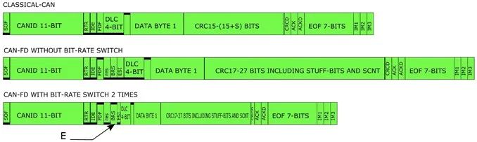
In Figure 2, a third CAN frame is added. This third frame is a CAN FD frame with the same content as the middle CAN FD frame, but in this case, it is sent at twice the data rate of the middle CAN FD frame.
Figure 2 CAN FD Frame Without/With Increased 2x Data Rate
Because it has the same content, you will get the same DLC and data, but when CAN FD is sent at a higher bit rate, the BRS bit will be sent recessive (see E). The BRS bit is included in the CRC calculation, resulting in two different CRC contents even if the CAN-ID, DLC, and data are the same.
As seen in Figure 2, the first bit sent at a higher bit rate is the ESI bit, followed by the DLC, data bytes, and CRC bits. The last bit sent at a higher bit rate is the CRC delimiter. Thus, it can be understood that the higher bit rate applies not only to the data segment of CAN FD frames but also to the surrounding bits.
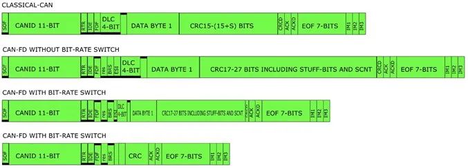
Figure 3 is the same as Figure 2, except for a new frame below the previously described frame. This new frame has the same content as all other frames, but the bit rate is eight times the arbitration bit rate. The variation is relatively large compared to CAN FD frames with constant bit rates or double bit rates.
It can be seen that not only does the single byte of data obtain a higher bit rate, but the DLC and CRC portions of the frame also have a total of about 40 bits.
Figure 4 shows three CAN frames, with the top being an 8-byte traditional CAN frame. The middle is a CAN FD frame with 64 bytes, and the bottom CAN frame is the same CAN FD frame content, but the bit rate is increased (speeding up eight times).
Figure 3 CAN FD Frame with 8x Increased Bit Rate Based on Figure 2
From Figure 4, it can be seen that more data will take longer to transmit the CAN frame, which will prevent other high-priority CAN frames from starting to send. To maintain real-time performance, it is necessary to increase the bit rate to reduce the length of the CAN frames and decrease the time they occupy the communication line, thus preventing other high-priority frames from accessing the communication.
Figure 4 Top is 8-byte Traditional CAN Frame;
Middle is 64-byte CAN FD Frame with Same Bit Rate;
Bottom is 64-byte CAN FD Frame with 8x Increased Bit Rate
In conclusion, high bit rate CAN FD will increase real-time performance as the higher bit rate shortens the transmission time of CAN frames, thus reducing communication delays. By transmitting more data in each frame, data throughput can be increased, but if not combined with a higher bit rate, this will reduce real-time performance. In many cases, 64-byte long CAN frames are used in programming, which usually occurs when the system is paused and there is no real-time control running. Even without real-time demands, using a higher bit rate to improve data throughput is still beneficial and shortens download times.
There are dozens of groups in the automotive industry, including complete vehicles, key components, new energy vehicles, intelligent connected vehicles, aftermarket, automotive investment, autonomous driving, and vehicle networking. To join a group, please scan the administrator’s WeChat (Please indicate your company name). There is also a startup financing group; welcome angel round and A-round companies to join;