Click to follow the above “Two Monkey Society“
Set as “Top or Star“, and the valuable content will be delivered first.

IC Monkey | Two Monkey Society
Introduction
The previous articles have covered the design part, and this article will analyze the simulation part of the code. This article mainly explains the overall simulation method and testbench structure of UART.
Simulation Framework
The structure and design of the simulation part are similar, with models for baud rate, receiving data, and sending data. The implementation of the simulation is quite flexible, without considering synthesizability. The main function is to implement the master functionality, configure the DUT, send data to the DUT through the sending model, and compare the received data with the sent data in the receiving model to verify the correctness of basic functionality.
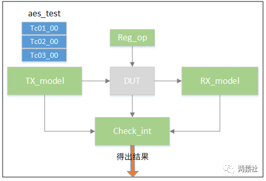
The top-level simulation generates clock and reset signals, initializes signals, selects test cases, and defines global variables or parameters (such as register addresses and variables needed by multiple modules).
////////////////////////////////////////
`timescale 1ns/1ps
//`define tc01_00
//`define tc02_00
`define tc03_00

module    top();


reg            clk;                 // ARM clk
reg            clk26m;              // 26M function clk
reg            rst_;                // ARM clk's rst_
reg            rst26m_;             // function clk's rst_
reg            tx_data;             // send data line
wire           rx_data;             // receive data line
wire           uart_int;            // uart interrupt


// APB signals
reg  [3:0]     paddr;
reg  [31:0]    pwdata;
reg            psel;
reg            penable;
reg            pwrite;
wire [31:0]    prdata;

reg            baud_tclk;           // send data baud clk
reg            baud_rclk;           // receive data baud clk
reg            start;               // receive data baud enable signal
reg            rx_done;             // receive one data done
reg            w_state;             // write reg using signal
reg            r_state;             // read reg using signal
reg  [7:0]     tx_data_mem[0:999];  // send data memory
reg  [7:0]     rx_data_mem[0:999];  // receive data memory

reg  [31:0]    uart_tx;
reg  [31:0]    uart_rx;
reg  [31:0]    uart_baud;
reg  [31:0]    uart_conf;
reg  [31:0]    uart_rxtrig;
reg  [31:0]    uart_txtrig;
reg  [31:0]    uart_delay;
reg  [31:0]    uart_status;
reg  [31:0]    uart_rxfifo_stat;
reg  [31:0]    uart_txfifo_stat;

// when tx_model is running a second time, we don't want tx_cnt to be cleared,
// so define tx_cnt in top
integer        tx_cnt;

parameter      clk_period            = 10;
parameter      clk26m_period         = 38;
parameter      uart_tx_addr          = 4'h0;
parameter      uart_rx_addr          = 4'h1;
parameter      uart_baud_addr        = 4'h2;
parameter      uart_conf_addr        = 4'h3;
parameter      uart_rxtrig_addr      = 4'h4;
parameter      uart_txtrig_addr      = 4'h5;
parameter      uart_delay_addr       = 4'h6;
parameter      uart_status_addr      = 4'h7;
parameter      uart_rxfifo_stat_addr = 4'h8;
parameter      uart_txfifo_stat_addr = 4'h9;

`include "UART_baud.v"
`include "reg_op.v"
`include "check_int.v"
`include "uart_tx_model.v"
`include "uart_rx_model.v"
`include "tc01_00.v"
`include "tc02_00.v"
`include "tc03_00.v"

// cases of uart
UART_TOP    DUT(
        .clk(clk),
        .clk26m(clk26m),
        .rst_(rst_),
        .rst26m_(rst26m_),
        .paddr_i(paddr),
        .pwdata_i(pwdata),
        .psel_i(psel),
        .penable_i(penable),
        .pwrite_i(pwrite),
        .urxd_i(tx_data),
        .utxd_o(rx_data),
        .uart_int_o(uart_int),
        .prdata_o(prdata)
);

// always produce clk
always    #(clk_period/2)    clk = ~clk;
always    #(clk26m_period/2) clk26m = ~clk26m;


// signals initialize
initial begin
    clk         = 1'b0;
    clk26m      = 1'b0;
    rst_        = 1'b1;
    rst26m_     = 1'b1;
    baud_tclk   = 1'b0;
    baud_rclk   = 1'b0;
    tx_data     = 1'b1;
    start       = 1'b0;
    rx_done     = 1'b0;
    w_state     = 1'b0;
    r_state     = 1'b0;
    uart_tx     = 32'h0;
    uart_baud   = 32'hf152;
    uart_conf   = 32'h34;
    uart_rxtrig = 32'h1;
    uart_txtrig = 32'h0;
    uart_delay  = 32'h2;
    uart_status = 32'h0;
    tx_cnt      = 0;
    #50;
    rst_      = 1'b0;
    rst26m_   = 1'b0;
    #100;
    rst_      = 1'b1;
    rst26m_   = 1'b1;

end


initial begin
    @(posedge rst_) begin end
    fork
        UART_baud();
        check_int();
        uart_rx_model();
    join
end


initial begin
    @(posedge rst_) begin end
    `ifdef tc01_00  tc01_00(10); `endif
    `ifdef tc02_00  tc02_00(); `endif
    `ifdef tc03_00  tc03_00(); `endif
end

endmodule
Note: Each register should have a reset value when reset, and each input should have an initial value during simulation to ensure functionality correctness and smooth simulation.
For beginners or those who frequently use GUI simulations, it is important to understand that when including tasks or functions, you can directly use
`include "userfile.v"
or
`include "D:/userdir/userfile.v"
The difference between the two is that the former requires specifying an include directory that contains the files to be included; while the latter uses an absolute path, which is more direct. However, when your simulation environment requires porting or includes many scattered files, the first method is more convenient.
The top-level simulation mainly connects various models with the DUT, forming the configuration and data transmission paths for the serial port. Additionally, it tests the functionality correctness under different configurations by controlling different simulation cases.
Test Case Description
All test cases use a pseudo-random method, meaning that data and configuration information are generated using the system random function.
tc01_00: Verification of the DUT’s receiving functionality. Randomly configure the baud rate and serial port functionality settings, with the FIFO trigger value for sending and receiving set to 32’ha. Control the sending data model to send data to the DUT, with the number of sends controllable via task input (in multiples of 10). When the RX FIFO trigger value is reached in the design, an interrupt will be triggered, and the check int module will continuously check for the interrupt and perform data comparison.
task  tc01_00;
input  integer    run_num;

reg  [9:0]         baud;
reg  [2:0]         conf;
reg     [15:0]             rdata;
integer            i;
integer            run_time;
integer            seed;

run_time = 0;
seed     = 0;
// memory initialize
for(i=0;i<1000;i++) begin
    top.tx_data_mem[i] = {$random} % 255;    //$dist_uniform(seed,5,255);
end
repeat(run_num) begin
    baud = $dist_uniform(seed,13,676);
    conf = {$random} % 7;   //$dist_uniform(seed,0,7);
    @(posedge top.clk) begin end
    write_reg(top.uart_baud_addr,{20'hf,2'b0,baud});
    @(posedge top.clk) begin end
    write_reg(top.uart_txtrig_addr,32'ha);
    @(posedge top.clk) begin end
    write_reg(top.uart_rxtrig_addr,32'ha);
    @(posedge top.clk) begin end
    write_reg(top.uart_conf_addr,{26'h0,3'b111,conf});

      uart_tx_model(10);

    $display("------run -------%d ",run_time);
    run_time++;
    seed++;
end
$stop;
endtask
tc02_00: Verification of the DUT’s sending functionality. Randomly configure baud rate, functionality, delay, and FIFO trigger values. After configuring the registers, set the serial port sending register to make the DUT send data (repeated 1000 times), and compare the data received by the receiving model with the sent data to verify functionality correctness.
task  tc02_00;

reg  [9:0]         baud;
reg  [2:0]         conf;
reg  [3:0]         delay;
reg  [3:0]         rxtrig;
reg  [3:0]         txtrig;

integer            i;
integer            j;
integer            seed;

seed     = 0;
j        = 0;
// memory initialize
for(i=0;i<1000;i++) begin
    top.tx_data_mem[i] = $dist_uniform(seed,5,255);
end

begin
    baud  = $dist_uniform(seed,13,676);
    conf  = $dist_uniform(seed,0,7);
    delay = $dist_uniform(seed,0,15);
    rxtrig = $dist_uniform(seed,4,14);
    txtrig = $dist_uniform(seed,4,14);
    write_reg(top.uart_baud_addr,{20'hf,2'b0,baud});
    @(posedge top.clk) begin end
    write_reg(top.uart_txtrig_addr,{28'h0,txtrig});
    @(posedge top.clk) begin end
    write_reg(top.uart_rxtrig_addr,{28'h0,rxtrig});
    @(posedge top.clk) begin end
    write_reg(top.uart_conf_addr,{26'h0,3'b111,conf});
    @(posedge top.clk) begin end
    write_reg(top.uart_delay_addr,{28'h0,delay});
    repeat(16) begin
        @(posedge top.clk) begin end
        write_reg(top.uart_tx_addr,top.tx_data_mem[j]);
        j++;
        if(j > 999) begin
            j = 0;
        end
        $display("write %d data",j);
    end
    seed++;
end
endtask
tc03_00: DUT send and receive test. Randomly configure baud rate, functionality, delay, and FIFO trigger values. After configuring the registers, set the serial port sending register to make the DUT send data (repeated 1000 times); then use the sending data model to send data 1000 times.
task  tc03_00;

reg  [9:0]         baud;
reg  [2:0]         conf;
reg  [3:0]         delay;
reg  [3:0]         rxtrig;
reg  [3:0]         txtrig;

integer            i;
integer            j;
integer            seed;


seed     = 0;
j        = 0;
// memory initialize
for(i=0;i<1000;i++) begin
    top.tx_data_mem[i] = $dist_uniform(seed,1,255);
end

begin
    baud  = $dist_uniform(seed,13,676);
    conf  = $dist_uniform(seed,0,7);
    delay = $dist_uniform(seed,0,15);
    rxtrig = $dist_uniform(seed,4,14);
    txtrig = $dist_uniform(seed,4,14);
    write_reg(top.uart_baud_addr,{20'hf,2'b0,baud});
    @(posedge top.clk) begin end
    write_reg(top.uart_txtrig_addr,{28'h0,txtrig});
    @(posedge top.clk) begin end
    write_reg(top.uart_rxtrig_addr,{28'h0,rxtrig});
    @(posedge top.clk) begin end
    write_reg(top.uart_conf_addr,{26'h0,3'b111,conf});
    @(posedge top.clk) begin end
    write_reg(top.uart_delay_addr,{28'h0,delay});
    fork
    repeat(16) begin
        @(posedge top.clk) begin end
        write_reg(top.uart_tx_addr,top.tx_data_mem[j]);
        j++;
        if(j > 999) begin
            j = 0;
        end
        $display("write %d data",j);
    end
    uart_tx_model(1000);
    join
    seed++;
end
endtask
This design only uses three test cases, and the simulation verification of the module is not complete. Readers can add different functional cases based on their usage.