Many developers using the serial-parallel driving CMOS integrated circuit74HC164 have reported ghosting (segments that should not be lit are slightly glowing). It is better to switch to74HC595. However, it is possible to achieve ghost-free operation using74HC164 to drive seven-segment displays with the synchronous serial port of the STM32F103 microcontroller. The STM32F103 microcontroller is limited in baud rate during synchronous transmission; at a clock speed of 48MHz, the baud rate can range from 460800 to 3000000 without flickering and ghosting. In contrast, the domestic Qinheng microcontrollerCH32V003F4P6 has no such baud rate limitations during transmission, achieving excellent display results. During development, you can chooseCH32V003F4P6 microcontroller, which is inexpensive, costing only a few dimes, and importantly, it is a 32-bit microcontroller, which can also breathe new life into the74HC164. The 74HC164 is a CMOS circuit,with a supply voltage range of2Vto6V, while the74LS164chip is a TTL circuit, suitable for4.75Vto5.25Vsupply voltage range. Therefore, the former is more suitable for 3.3V powered systems. If you only have one74HC164 and the other is74LS164, it is also acceptable. When using an 8-digit common cathode seven-segment display, the segment code can be driven by74HC164 to output a higher high level, while the scanning bit code can be driven by74LS164, which can also achieve normal brightness. When driving an 8-digit common anode seven-segment display, swapping the positions of the two 164s can still achievenormal brightness display.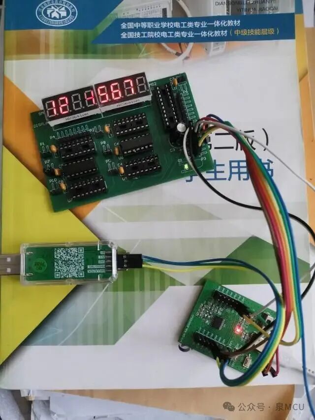 The image shows the numbers 12345678; the reason some segments do not light up is due to the camera’s limitations. The baud rate and the microcontroller clock are both at 48MHz.
It should be noted that: in STM32, the serial port can be initialized first, followed by the serial port clock initialization:
USART_Init(USART1, &USART_InitStructure); //Initialize serial port
USART_ClockInit(USART1,&clk_usart); //Initialize serial port clock
However, the CH32003F4P6 microcontroller does not allow this; the serial port clock must be initialized first, followed by the serial port initialization, which means that the serial port clock initialization is considered part of the serial port initialization.
The code is as follows:
//CH32V003F4P6 synchronous serial control of 2 74HC164 to drive 8 common cathode integrated seven-segment displays segment code and scanning bit code Ghosting is not visible in weak daylight, and there is no flickering. // It is best to use two 74HC164s; if 74HC164 is really lacking, since it drives common cathode displays, the segment code must use 74HC164, while the scanning bit code can use 74LS164. // Completely eliminate ghosting. // 3.3V power supply Only occupies 3 GPIOs. // Download successful /********************************** (C) COPYRIGHT ******************************* * File Name : main.c * Author : * Version : V1.0.0 * Date : 2025/9/13 * Description : Main program body. ********************************************************************************* * Copyright (c) 2021 Nanjing Qinheng Microelectronics Co., Ltd. * Attention: This software (modified or not) and binary are used for * microcontroller manufactured by Nanjing Qinheng Microelectronics. *******************************************************************************//* *@Note CH32V003F4P6 synchronous serial application */#include "debug.h"//unsigned char SEG_CODE[] = // { 0xC0,0xF9,0xA4,0xB0,0x99,0x92, 0x82,0xF8,0x80,0x90,0xFF };//Common anode seven-segment display codes for 0~9, off segments, in reverse order; hardware segments A~H correspond to D7~D0 unsigned char Nixu_SEG_CODE[] = { 0x03,0x9f,0x25,0x0d,0x99,0x49, 0x41,0x1f,0x01,0x09,0xFF }; unsigned char buff[8] = {1,2,3,4,5,6,7,8};//==============Hardware Interface========================//PD3----74HC164_Pin9 Reset pin #define RST_1 GPIO_SetBits(GPIOD,GPIO_Pin_3) //PD3 output high #define RST_0 GPIO_ResetBits(GPIOD,GPIO_Pin_3) //PD3 output low //PD5/TX1---74HC164_Pin1_2 Data pin, the Q7 of the previous 74HC164 connects to the data pin of the next one //PD4/CK1---74HC164_Pin8 Clock //PD6/RX1 Not used in this example /********************************************************************* * @fn GPIO_Toggle_INIT * * @brief Initializes GPIOD.3 * //PD3----74HC164_Pin9 Reset pin * * @return none */void GPIO_Toggle_INIT(void){ GPIO_InitTypeDef GPIO_InitStructure = {0}; RCC_APB2PeriphClockCmd(RCC_APB2Periph_GPIOD, ENABLE); GPIO_InitStructure.GPIO_Pin = GPIO_Pin_3; GPIO_InitStructure.GPIO_Speed = GPIO_Speed_50MHz; GPIO_InitStructure.GPIO_Mode = GPIO_Mode_Out_PP; //General push-pull output GPIO_Init(GPIOD, &GPIO_InitStructure);}/********************************************************************* * @fn USARTx_CFG Serial port initialization configuration * * @brief Initializes the USART2 & USART3 peripheral. * * @return none * In STM32, the serial port can be initialized first, followed by the serial port clock initialization: USART_Init(USART1, &USART_InitStructure); //Initialize serial port USART_ClockInit(USART1,&clk_usart); //Initialize serial port clock* However, the CH32003F4P6 microcontroller does not allow this; the serial port clock must be initialized first, followed by the serial port initialization, * which means that the serial port clock initialization is considered part of the serial port initialization. */void USARTx_CFG(void){ GPIO_InitTypeDef GPIO_InitStructure = {0}; //GPIO structure USART_InitTypeDef USART_InitStructure = {0}; //Serial port structure USART_ClockInitTypeDef USART_ClockInitStructure = {0}; //Serial port clock structure RCC_APB2PeriphClockCmd(RCC_APB2Periph_GPIOD | RCC_APB2Periph_USART1, ENABLE); /* USART1 TX-->D.5 RX-->D.6 */ GPIO_InitStructure.GPIO_Pin = GPIO_Pin_5; //TX1 pin GPIO_InitStructure.GPIO_Speed = GPIO_Speed_50MHz; GPIO_InitStructure.GPIO_Mode = GPIO_Mode_AF_PP; //Must be multiplexed push-pull output GPIO_Init(GPIOD, &GPIO_InitStructure); GPIO_InitStructure.GPIO_Pin = GPIO_Pin_6; //RX1 pin GPIO_InitStructure.GPIO_Speed = GPIO_Speed_50MHz; GPIO_InitStructure.GPIO_Mode = GPIO_Mode_IN_FLOATING; //Floating input GPIO_Init(GPIOD, &GPIO_InitStructure); GPIO_InitStructure.GPIO_Pin=GPIO_Pin_4; //The CK pin of serial port 1 is PD4 by default GPIO_InitStructure.GPIO_Speed=GPIO_Speed_50MHz; GPIO_InitStructure.GPIO_Mode=GPIO_Mode_AF_PP; //Must be multiplexed push-pull output //GPIO_InitStructure.GPIO_Mode=GPIO_Mode_Out_PP; //General push-pull output GPIO_Init(GPIOD,&GPIO_InitStructure); //Initialize GPIOD.4 //First initialize the serial port clock USART_ClockInitStructure.USART_Clock = USART_Clock_Enable; //Enable clock CK USART_ClockInitStructure.USART_CPOL = USART_CPOL_Low; //Clock idle state is low USART_ClockInitStructure.USART_CPHA = USART_CPHA_1Edge; //Set serial port clock phase to capture data on the first edge of clock change USART_ClockInitStructure.USART_LastBit = USART_LastBit_Enable; //Send clock pulse after the last data bit USART_ClockInit(USART1,&USART_ClockInitStructure); //Initialize serial port clock //For STM32F103zet6, clock 48MHz, delay 2ms, baud rate between 460800~3000000 does not flicker, no ghosting //For CH32V003F4P6, clock 48MHz, delay 2ms, baud rate between 460800~4800000 does not flicker, no ghosting; lower baud rates have severe ghosting USART_InitStructure.USART_BaudRate = 4800000; //Baud rate USART_InitStructure.USART_WordLength = USART_WordLength_8b; //Data format is 8 bits USART_InitStructure.USART_StopBits = USART_StopBits_1; //One stop bit USART_InitStructure.USART_Parity = USART_Parity_No; //No parity bit //No hardware flow control mode USART_InitStructure.USART_HardwareFlowControl = USART_HardwareFlowControl_None; USART_InitStructure.USART_Mode = USART_Mode_Tx | USART_Mode_Rx; //Enable transmission and reception //Finally, initialize the serial port USART_Init(USART1, &USART_InitStructure); //Initialize serial port USART_ITConfig(USART1,USART_IT_RXNE,ENABLE); //Enable interrupt, interrupt on data received USART_Cmd(USART1,ENABLE); //Enable serial port USART_ClearFlag(USART1,USART_FLAG_TC); //Clear flag }/********************************************************************* * @fn main * * @brief Main program. * * @return none */int main(void){ u8 k; //Set interrupt priority grouping to 1 NVIC_PriorityGroupConfig(NVIC_PriorityGroup_1); //Update the system core clock variable SystemCoreClock according to the current clock configuration. SystemCoreClockUpdate(); Delay_Init(); /******************* //Synchronous serial control of 74HC164, do not send data to the serial port#if (SDI_PRINT == SDI_PR_OPEN) SDI_Printf_Enable();#else USART_Printf_Init(115200);#endif printf("SystemClk:%d\r\n",SystemCoreClock); printf( "ChipID:%08x\r\n", DBGMCU_GetCHIPID() ); ************************/ GPIO_Toggle_INIT(); //GPIO initialization configuration USARTx_CFG(); //Serial port initialization configuration while (1) { for(k = 0;k < 8;k++) { RST_0; //Reset both 164s to output 0 RST_1; //Pull high both 164 reset pins to allow output USART_SendData(USART1,~(0x80 >> k)); //Send data via serial port, output scanning bit code to 74HC138 while(USART_GetFlagStatus(USART1,USART_FLAG_TC)!=SET); //Wait for transmission to finish USART_SendData(USART1,~Nixu_SEG_CODE[buff[k]]); //Send segment code data via serial port while(USART_GetFlagStatus(USART1,USART_FLAG_TC)!=SET); //Wait for transmission to finish Delay_Ms(2); } }}