In embedded development, a stable and reliable display is often the core of human-machine interaction. Today, we will take a deep dive into the ST7656P driven LCD12864 dot matrix display, covering everything from hardware connections to code implementation, with a particular focus on the generation and reading of character patterns and images, allowing you to quickly get started with this classic display module.
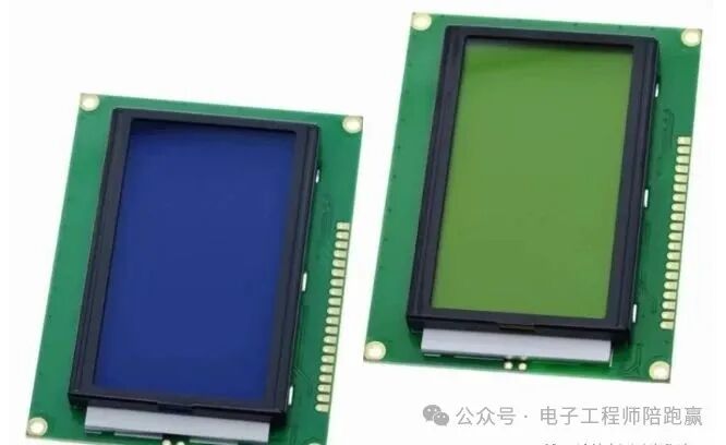
1. Introduction to ST7656P and LCD12864 The LCD12864 is a 128×64 dot matrix graphic display module, and the ST7656P is its “brain”—the core chip responsible for driving the screen display. The ST7656P, as a dedicated LCD controller, supports SPI serial interface (some models also support parallel), efficiently receiving commands and data from the microcontroller to control the on/off state of each pixel. It has built-in display RAM, allowing it to directly store 128×64 dot matrix display data without the need for external memory, making it very suitable for small embedded devices. Typical application scenarios include: – Instruments: Displaying temperature, humidity, voltage, current measurement data – Portable devices: Text/menu display for electronic dictionaries, handheld terminals – Industrial control: Device operating status, fault code prompts – Smart home: Interactive interfaces for thermostats, smart switches.
2. Hardware Connection: Simple Steps to Set Up the Circuit Taking the STM32 microcontroller as an example, the SPI connection method is as follows (only 5 core pins are needed): Table 1
Wiring Notes: – Be sure to use a 3.3V power supply to avoid damaging the chip with 5V – If the screen backlight is not lit, check whether the backlight pins (usually LED+ and LED-) are connected correctly to the power supply.
3. Initialization: Wake Up the Screen Any peripheral device needs to be initialized before use, and the LCD12864 is no exception. The core of initialization is to send configuration commands to the ST7656P via SPI. The steps are as follows: Initialization Flowchart Start | ├─ Configure the SPI pins of STM32 (SCK, MOSI) and control pins (CS, RST, DC) to output mode | ├─ Hardware reset operation │ ├─ Pull down the RST pin (for at least 1μs) │ ├─ Pull up the RST pin │ └─ Delay 10ms (wait for the chip to stabilize) | ├─ Send initialization commands (via the write command function) │ ├─ Send 0xAE (turn off display to avoid garbled characters during initialization) │ ├─ Send 0x40 (set display start line to the 0th line) │ ├─ Send 0xB0 (set initial page address to the 0th page) │ ├─ Send 0x10 (set high 4 bits of column address to 0x0) │ ├─ Send 0x00 (set low 4 bits of column address to 0x0) │ └─ Send 0xAF (turn on display, completing initialization) | End
Code Implementation 1. Hardware reset Pull down the RST pin for at least 1μs, then pull it up, waiting 10ms for the chip to stabilize:
HAL_GPIO_WritePin(RST_PORT, RST_PIN, GPIO_PIN_RESET); // Reset HAL_Delay(1); HAL_GPIO_WritePin(RST_PORT, RST_PIN, GPIO_PIN_SET); // End reset HAL_Delay(10);2. Send initialization commands sequentially send the following commands (implemented via the write command function): – 0xAE: Turn off display (turn off screen during initialization to avoid garbled characters) – 0x40: Set display start line (starting from the 0th line) – 0xB0: Set page address (default to the 0th page, total of 8 pages) – 0x10 | 0x00: Set column address (high 4 bits + low 4 bits, starting from the 0th column) – 0xAF: Turn on display. At this point, the screen enters a ready state, prepared to receive display data.
4. Core Functions: Control the Screen’s “Left Hand” and “Right Hand” To achieve display functionality, two basic functions need to be encapsulated: write command and write data. 1. Write Command Function (Configure Screen Parameters)
void LCD_WriteCmd(uint8_t cmd) { HAL_GPIO_WritePin(CS_PORT, CS_PIN, GPIO_PIN_RESET); // Select chip HAL_GPIO_WritePin(DC_PORT, DC_PIN, GPIO_PIN_RESET); // Command mode HAL_SPI_Transmit(&hspi1, &cmd, 1, 100); // Send command HAL_GPIO_WritePin(CS_PORT, CS_PIN, GPIO_PIN_SET); // Deselect chip}2. Write Data Function (Send Display Content)
void LCD_WriteData(uint8_t data) { HAL_GPIO_WritePin(CS_PORT, CS_PIN, GPIO_PIN_RESET); // Select chip HAL_GPIO_WritePin(DC_PORT, DC_PIN, GPIO_PIN_SET); // Data mode HAL_SPI_Transmit(&hspi1, &data, 1, 100); // Send data HAL_GPIO_WritePin(CS_PORT, CS_PIN, GPIO_PIN_SET); // Deselect chip}Tip: When using SPI communication, it is recommended that the clock frequency does not exceed 12.5MHz to avoid data transmission errors. 5. Character Pattern and Image Generation and Reading: Making Content “Visible” The core of the LCD12864 display of characters and images is to convert dot matrix information into binary data (i.e., “patterns”), and then send it to the screen. Below is a detailed explanation of the generation, storage, and reading methods for character patterns and images. 1. Character Pattern Generation and Reading (Taking 8×16 Dot Matrix ASCII Characters as an Example) (1) Character Pattern Generation It is recommended to use the “PCtoLCD2002” character pattern software, with the following steps: – Set parameters: Click “Options”, select “Inverse Code” (light is 1, dark is 0), “Line by Line” (scanning by line), “C51 Format” (generate array), set dot matrix to “8×16” (width 8 columns, height 16 rows). – Generate character pattern: Input the character (e.g., “A”) in the input box, click “Generate Pattern”, and the software will automatically generate 16 bytes of data (8×16 dot matrix has a total of 128 points, 128/8=16 bytes). For example, the character pattern for “A” may be: 0x00,0x18,0x3C,0x66,0xC3,0xC3,0xFF,0xC3,0xC3,0xC3,0x00,0x00,0x00,0x00,0x00,0x00, (2) Character Pattern Storage (Establish Character Pattern Library) Store the generated character patterns in an array in ASCII code order, as a character pattern library:
// 8×16 Dot Matrix ASCII Character Pattern Library (starting with space (0x20)) uint8_t Font8x16[][16] = { {0x00,0x00,0x00,0x00,0x00,0x00,0x00,0x00,0x00,0x00,0x00,0x00,0x00,0x00,0x00,0x00}, // Space (0x20) {0x00,0x00,0x00,0x00,0x00,0x00,0x1F,0x1F,0x1F,0x1F,0x00,0x00,0x00,0x00,0x00,0x00}, // '!' (0x21) // ... Other characters omitted, arranged in ASCII order {0x00,0x18,0x3C,0x66,0xC3,0xC3,0xFF,0xC3,0xC3,0xC3,0x00,0x00,0x00,0x00,0x00,0x00}, // 'A' (0x41) // ... Continue adding other characters};(3) Character Pattern Reading (Display Character) Calculate the offset based on the ASCII code of the character, read the corresponding data from the character pattern library, and send it to the screen:
// Display a single character (page: starting page, col: starting column, ch: character) void LCD_ShowChar(uint8_t page, uint8_t col, uint8_t ch) { uint8_t index = ch - 0x20; // Calculate character pattern index (ASCII code minus the ASCII code of space 0x20) // Display the upper half 8 rows (occupying the page) LCD_SetPos(page, col); for(uint8_t i=0; i<8; i++) { LCD_WriteData(Font8x16[index][i]); } // Display the lower half 8 rows (occupying page+1) LCD_SetPos(page+1, col); for(uint8_t i=0; i<8; i++) { LCD_WriteData(Font8x16[index][i+8]); }} 2. Image Generation and Reading (Taking 64×64 Dot Matrix Images as an Example) (1) Image Generation It is recommended to use the “Image2Lcd” image conversion software, with the following steps: – Prepare the image: Crop the image to 64×64 pixels (matching the screen height), save it as a black and white bitmap (.bmp format). – Software settings: Input the image path, set “Output Data Type” to “C language array”, “Scan Mode” to “Horizontal Scan”, “Output Grayscale” to “Monochrome”, and “Byte Order” to “Normal”. – Generate image data: Click “Convert”, and the software will generate 64×64/8=512 bytes of data (each byte represents 8 pixels). (2) Image Storage Store the generated image data in an array (stored by page, with each 8 rows corresponding to 1 page, for a total of 8 pages):
// 64×64 Dot Matrix Image Data (Example: A Simple Graphic) uint8_t Image64x64[8][128] = { {0x00,0x00,...,0x00}, // Page 0 (Rows 0-7) {0x00,0x0F,...,0x00}, // Page 1 (Rows 8-15) // ... Omitted intermediate page data {0x00,0x00,...,0x00} // Page 7 (Rows 56-63)};(3) Image Reading (Display Image) Traverse the image data by page and send it to the corresponding column address of each page:
// Display 64×64 image (starting from the top left corner of the screen at position 0,0) void LCD_ShowImage() { for(uint8_t page=0; page<8; page++) { // Traverse 8 pages LCD_SetPos(page, 0); // Position to the current page's 0th column for(uint8_t col=0; col<128; col++) { // Traverse 128 columns LCD_WriteData(Image64x64[page][col]); // Send current page's current column data } }} 6. Other Display Function Implementations1. Set Display Position The LCD12864 screen is divided into 8 pages (vertically, 8 rows per page) and 128 columns (horizontally). The positioning function is as follows:
void LCD_SetPos(uint8_t page, uint8_t col) { LCD_WriteCmd(0xB0 | page); // Page address (0-7) LCD_WriteCmd(0x10 | (col >> 4)); // High 4 bits of column address LCD_WriteCmd(0x00 | (col & 0x0F)); // Low 4 bits of column address}2. Clear Screen Operation Traverse all pages and columns, writing 0x00 (turning off all pixels):
void LCD_Clear() { for(uint8_t page=0; page<8; page++) { LCD_SetPos(page, 0); for(uint8_t col=0; col<128; col++) { LCD_WriteData(0x00); } }}7. Pitfall Guide: Issues to Watch Out For1. Garbled Display/Image Misalignment: Check the SPI timing (whether clock polarity and phase are in mode 0), whether the initialization commands are complete, or whether the storage order of character patterns/images matches the screen scanning method. 2. Content Not Fully Displayed: Ensure that the character/image size does not exceed the screen range (128 columns × 64 rows), for example, an 8×16 character needs to occupy 2 pages and 8 columns, a 64×64 image needs to start displaying from column 0. 3. Character Pattern/Image Direction Error: If the content is upside down or mirrored, check the scanning method in the conversion software (whether it is set to “Horizontal Scan” or “Line by Line”). 4. Screen Ghosting: When displaying static images for a long time, it is recommended to clear the screen once an hour and redraw. Conclusion The ST7656P driven LCD12864 module offers high cost performance and simple programming. Once you master the generation and reading of character patterns and images, you can easily achieve character and graphic display. This article provides a one-stop explanation from hardware connection, initialization to data processing, and I believe it will help you get started quickly.
 Previous RecommendationsMechanical Keyboard Input Detection Based on F28335Configuration and Application of the eQEP Module of F28335Pulse Capture – In-depth Analysis of the eCAP Module Principles and Applications of F28335
The Bridge of Digital Control and Intelligent Manipulation – Detailed Explanation of DAC Expansion and Drive
The Important Bridge of Digital Control ADC – TMS320F28335 ADC Driver and Application Program Writing Experiment
Basic Programming and Debugging of DSP28335 for Serial Port Programming
Complete Guide to Configuring and Generating ePWM Programs for DSP28335 Using MATLABAnalysis of the Impact of Extreme Temperatures on Component PerformanceBuilding an Efficient and Stable Motor Control DSP Software Framework:In-depth Analysis of the Three-Level Interrupt Settings and Initialization of TMS320F28335Basic Experiment of ePWM Configuration of TMS320F28335Most Common 28335 ePWM Configuration Methods for Motor ControlThe Global Craze for the Legendary Chip! How TI C2000 is Reshaping Embedded Control History?Unveiling the Bridge Between Analog and Discrete PID Control: Difference EquationsIntelligent Self-Tuning Method for PID ParametersThoroughly Understanding the Structure, Differences, Conversion, and Application of “Serial” and “Parallel” PIDTrend Curve for Thoroughly Tuning PID ParametersKey Components of Robots (6) – Stepper MotorsKey Components of Robots (4) – DC Torque MotorsField Effect Transistor Series (9) – The Continuation and Drive of H-Bridge Circuits