1. Preparation
The Mecanum wheel robot is a type of robot that can achieve omnidirectional movement, with its core being the specially designed Mecanum wheels. To build a Mecanum wheel robot from scratch, you may need to prepare the following components and tools:
1. Materials and Components
Mecanum Wheels: Choose Mecanum wheels of the appropriate size and load capacity. These wheels are typically made of rubber or plastic and come with freely rotating rollers. They can be purchased from specialized robotics accessory stores or online marketplaces.
Motors: Select stepper motors or servo motors based on design requirements. The torque and speed of the motors should match the specifications of the Mecanum wheels. For small robots, NEMA17 stepper motors can be used.
Motor Controller: If using stepper motors, a corresponding driver such as the A4988 module is needed; if using servo motors, an ESC electronic speed controller is required. Ensure the controller can handle the required current and voltage.
Battery: Choose a suitable lithium battery or nickel-hydride battery based on the power requirements of the motors and control board. The capacity should be sufficient to support the expected operating time. Microcontrollers such as Arduino UNO, Nano, or Raspberry Pi are common choices. They are used to receive sensor data and control the motors.
Structural Frame: The body can be constructed using wood boards, acrylic boards, or 3D printed parts. Consider strength and weight during the design phase.
Sensors: Ultrasonic sensors are used for obstacle avoidance, and encoders can be used for wheel speed feedback to improve motion accuracy.
Other Electronic Components: Includes wires, sockets, resistors, LED indicators, etc.
2. Tools
Screwdriver: A set of Phillips and flathead screwdrivers for different sizes of screws.
Soldering Iron and Solder: For soldering electronic components to ensure solid and reliable connections.
Wire Stripper and Scissors: For preparing wires and cutting materials.
Ruler and Marker: For measuring and marking materials for accurate cutting.
Saw or Laser Cutter: For cutting based on the chosen material type.
3D Printer: If you have 3D design files, you can print complex parts directly.
Screw and Nut Set: Various sizes of screws and nuts for assembling the structure.
3. Software
Programming Environment: Arduino IDE for writing and uploading code to the Arduino board; PyCharm or Thonny for Python programming on Raspberry Pi; Keil5 and CubeMX for microcontroller programming.
CAD Software: Such as AutoCAD or SolidWorks, for designing and modifying the structural components of the vehicle.
Firmware Libraries: Such as Arduino’s Stepper or Servo libraries, to simplify the writing of motor control code.
4. Assembly Steps
Design Frame: Design the vehicle frame in CAD software, considering the layout of all components.
Print/Manufacture Parts: Use a 3D printer to print non-standard parts, or cut wood or acrylic boards according to the design.
Install Motors: Secure the motors to the frame and ensure the Mecanum wheels can rotate freely without obstruction.
Connect Electronic Components: Connect the motor controller, battery, microcontroller, and sensors according to the circuit diagram.
Upload Code: Write control code and run tests on the microcontroller.
Debug: Check if all movements meet expectations and adjust the code to optimize performance.
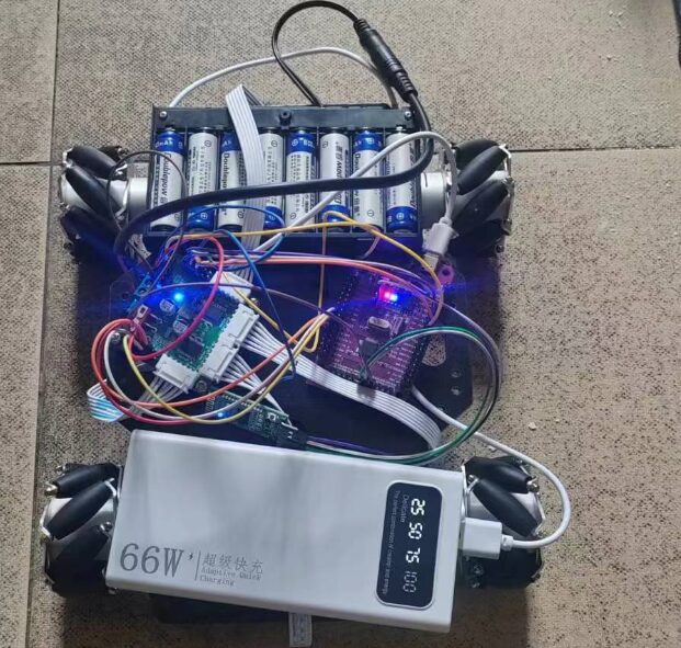
The chip model I used here is STM32F103C8T6, with the programming environment being Keil5 and CubeMX, the motor driver module is TB6612, and the Bluetooth module is HC-05 or HC-08. The floor wheels and motors can be purchased online.
For basic knowledge of motor drivers, you can refer to my previous article: https://blog.csdn.net/m0_74712453/article/details/140008931?spm=1001.2014.3001.5501
2. Working Principle of Mecanum Wheels
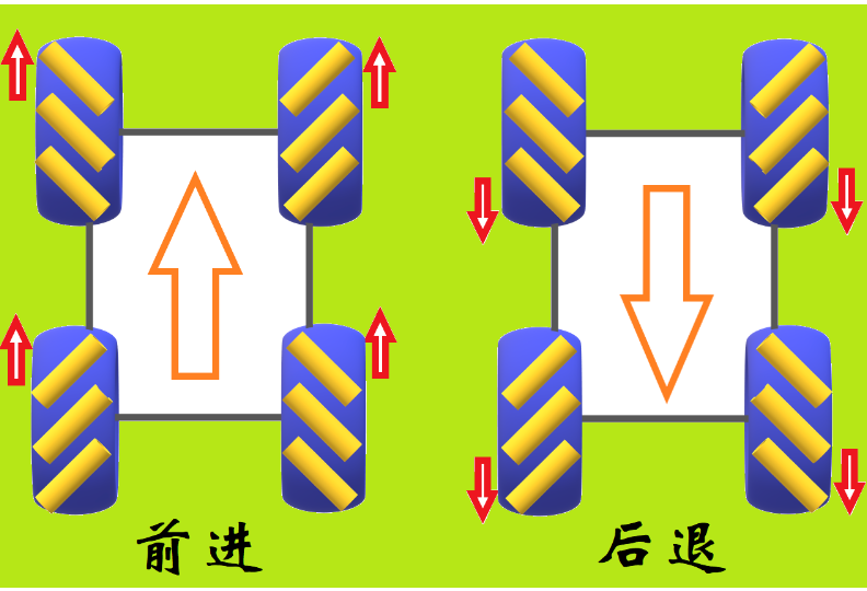
The core principle of Mecanum wheels is the unique layout and angle of the small rollers on the wheels, which can decompose the force transmitted from the hub into two components, one horizontal and one vertical to the roller axis. By appropriately controlling the relative speed and direction of the four Mecanum wheels, the vehicle can move in any direction without changing its body orientation. For example, when all wheels rotate forward, if the adjacent wheels rotate in opposite directions, the vehicle will slide sideways; if the wheels on the diagonal rotate in the same direction, it can achieve rotation in place.
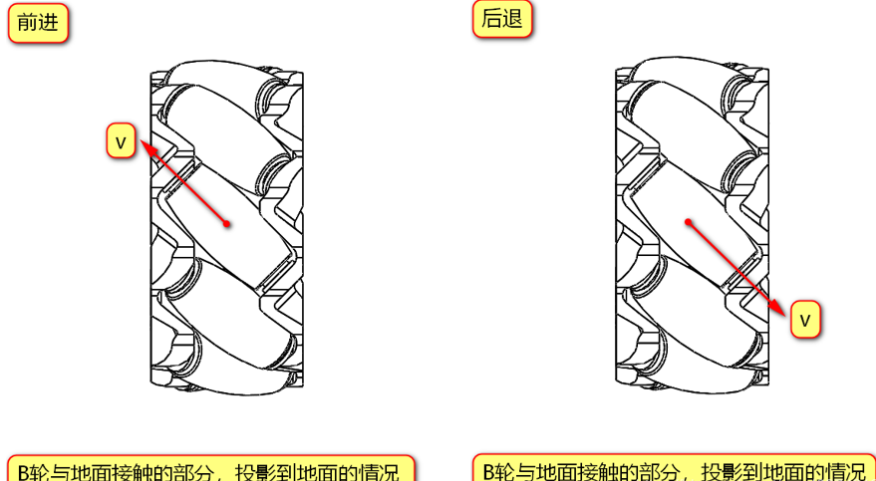
As mentioned earlier, the wheels are divided into types A and B. If wheel A moves forward while simultaneously moving to the right, it moves diagonally to the front right; conversely, if wheel A moves backward while simultaneously moving to the left, it moves diagonally to the back left; the corresponding wheel B can move diagonally to the front left and back right.
Example: Taking the front of the car as the positive direction, we define the direction of the wheel’s forward motion as the motor rotating forward, and the backward motion as the motor rotating in reverse.
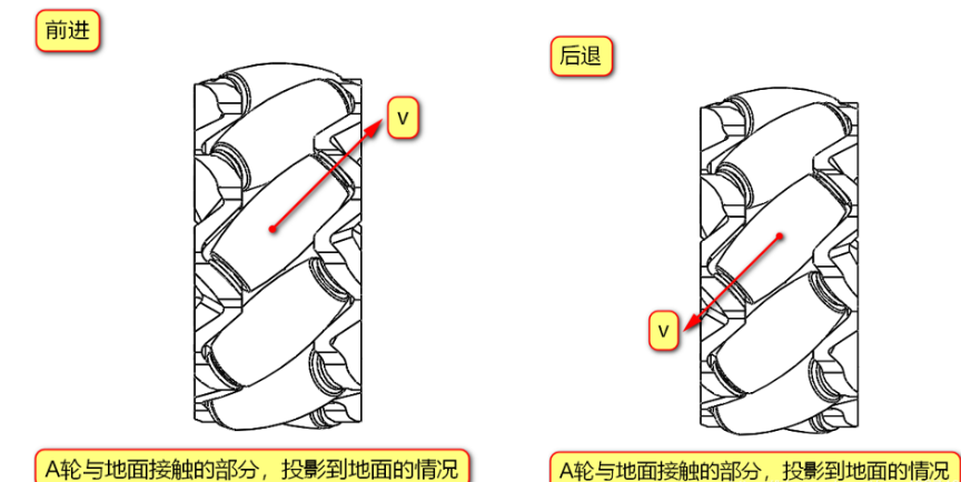
Taking wheel A as an example, due to rolling, the direction of movement of the rollers cannot provide forward force, while in the direction of the roller axis, the rollers cannot roll and create friction with the ground, resulting in frictional force in the diagonal right front or left back direction, thus the speed direction of wheel A is diagonal right front or left back; similarly, wheel B can be analyzed.
According to the physics knowledge we learned in high school, we know that velocity can be orthogonally decomposed, and the movement of the vehicle depends on the resultant velocity direction of the four Mecanum wheels.
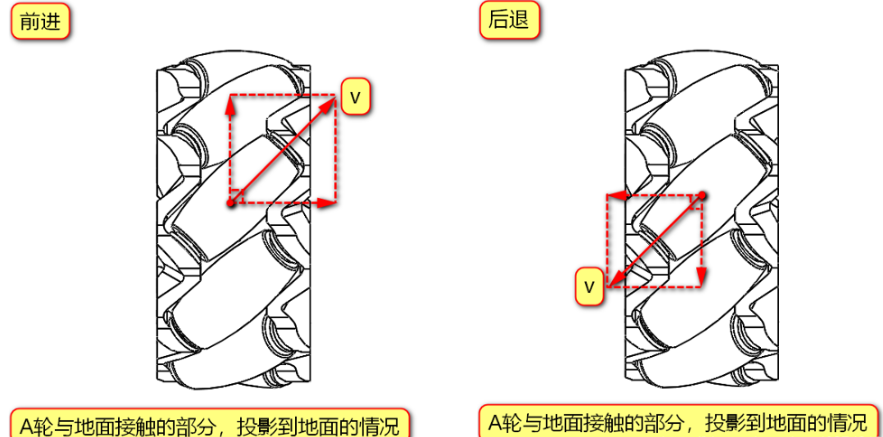
Thus, wheel A can be decomposed into axial speed components to the right and vertical speed components to the front, or axial speed components to the left and vertical speed components to the back.
In this way, the speed components of wheel B are mirror images of those of wheel A.
3. Installation Combination and Motion Analysis of Mecanum Wheels
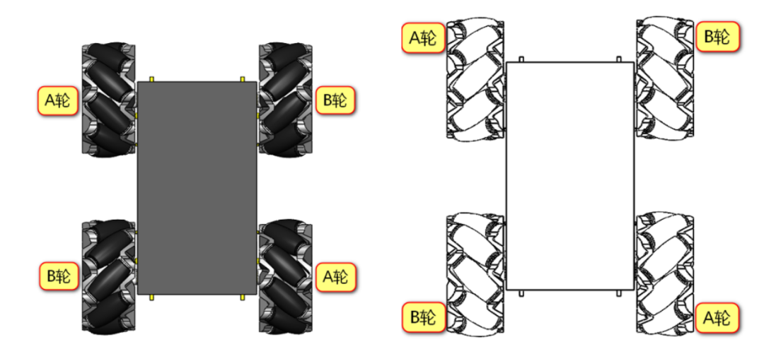
1. Correct Installation Combination of Mecanum Wheels
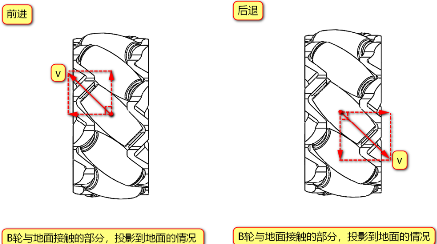
From the above, we can see that Mecanum wheels are mainly divided into types A and B. Knowing the corresponding speed components of the wheels, we can arrange and combine the four wheels of the Mecanum wheel chassis, for example: AABB, AAAA, BBBB, etc. However, through speed component analysis, we can determine that not every combination can achieve omnidirectional movement. Here, I will list one incorrect installation combination of Mecanum wheels; the rest can be inferred independently. For example, the incorrect example is AAAA type: the left image is a top view, and the right image shows the part of the Mecanum wheel that contacts the ground, projecting onto the ground!
From the diagram, we can see that when all four wheels rotate forward simultaneously, each wheel will have a leftward speed component, which will cause the entire chassis to inevitably move left while moving forward; similarly, when moving backward, it will inevitably move right, making it uncontrollable and unable to achieve the desired omnidirectional movement.
Therefore, we can ensure that the four wheels move forward or backward simultaneously without any other deviation by assembling them correctly.
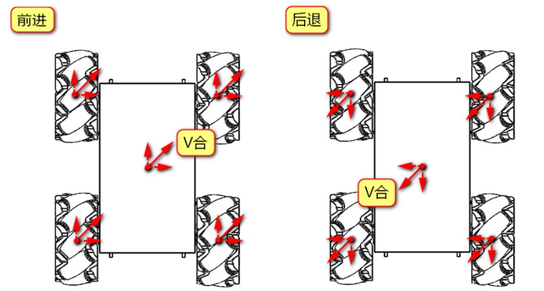
As shown in the figure below, here is one correct installation combination:
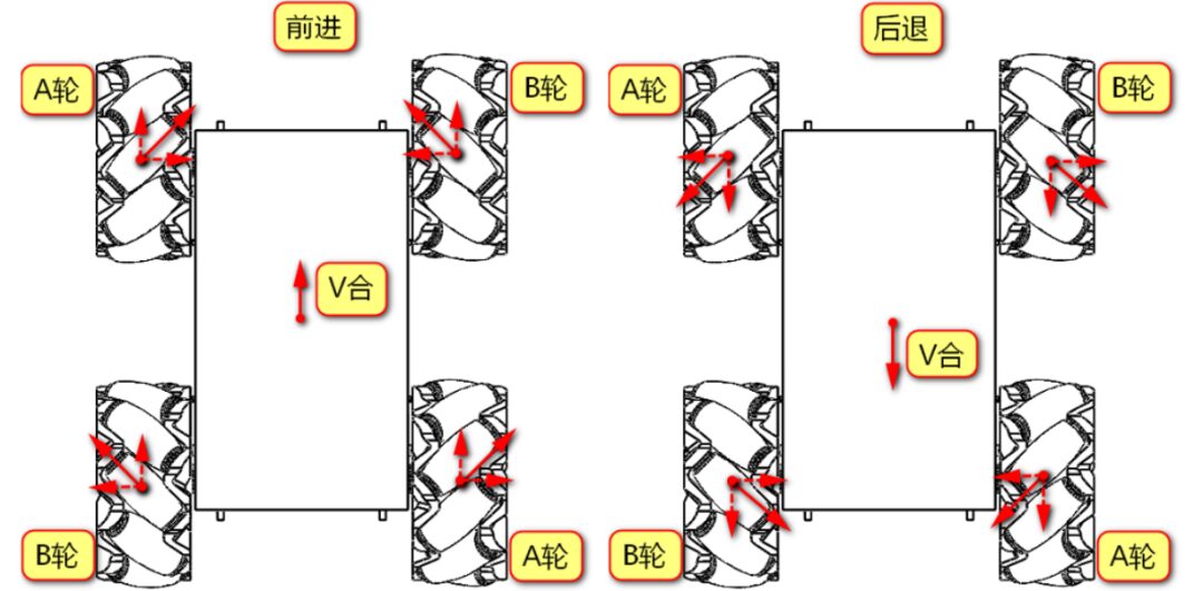
When all four wheels rotate forward, the A and B wheels can cancel out the axial speeds, leaving only the forward speed, so the chassis moves straight forward without deviation, and the same applies when moving backward.
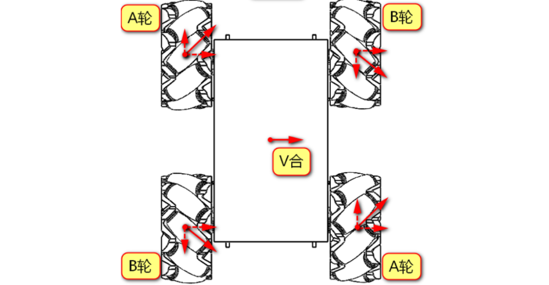
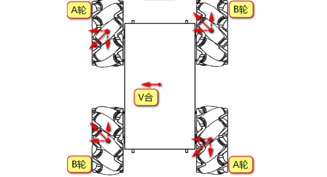
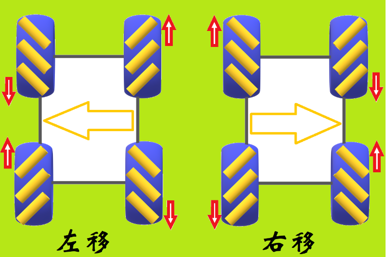
If wheel A rotates forward and wheel B rotates backward, the forward and backward speeds will cancel out, leaving only the rightward speed, causing the chassis to shift to the right; conversely, if wheel A rotates backward and wheel B rotates forward, it will shift to the left; other directions can be inferred independently. I have listed common Mecanum combinations and their movement directions in the previous article.
2. Common Motion Methods of Mecanum Wheels
Based on the principles above, we can derive the common motion methods of Mecanum wheels.
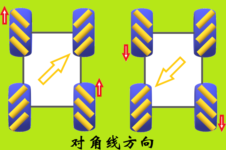
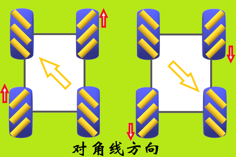
1. Diagonal Direction
2. Move Forward and Backward

3. Move Left and Right

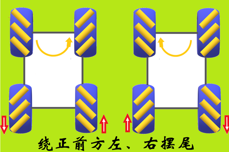
4. Swing Tail Left and Right Around the Front
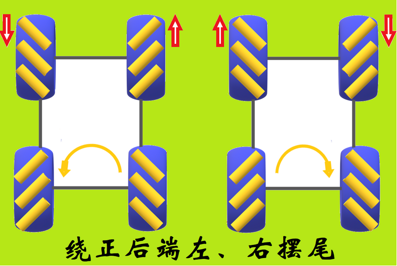
5. Swing Tail Left and Right Around the Back
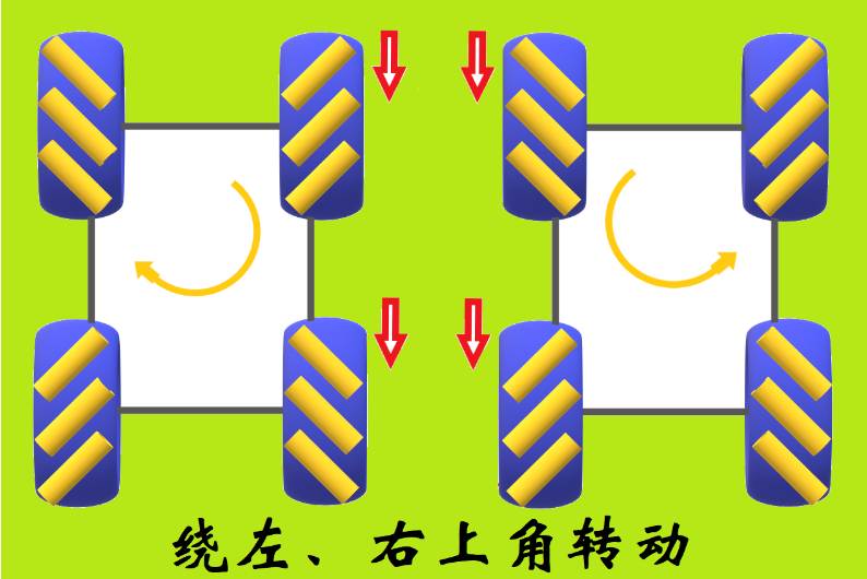
6. Rotate Around the Upper Left Corner
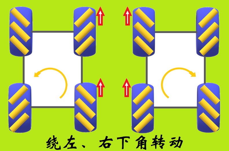
7. Rotate Around the Lower Left Corner
4. Writing Software Program Code
Here, we will first implement Bluetooth control for the robot to move forward, backward, and sideways. I will summarize the knowledge involving encoders and PID control in a separate article when I have time.
1. Wiring
Wiring between the motor driver module and the microcontroller:
AIN1, AIN2 corresponds to PB2, PB10 left upper wheel
BIN1, BIN2 corresponds to PB1, PB0 left lower wheel
DIN1, DIN2 corresponds to PB5, PB6 right upper wheel
CIN1, CIN2 corresponds to PB8, PB7 right lower wheel
HC-08 Bluetooth module wiring with the microcontroller:
Bluetooth module TX connects to RX (PA10), RX connects to TX (PA9), VCC connects to 5V, GND connects to GND
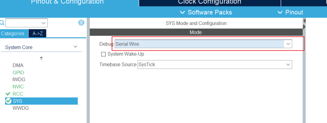
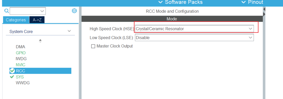
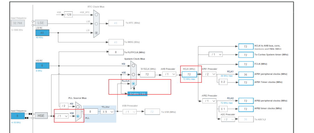
2. CubeMX Configuration
SYS: Set Debug to Serial Wire
RCC: Configure external high-speed crystal oscillator
Configure the clock tree:
Configure the eight GPIO ports as output mode:

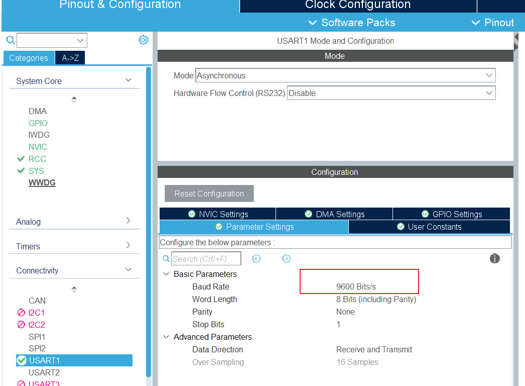
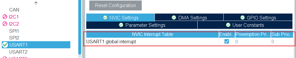
Configure UART: Set the baud rate to 9600, as the Bluetooth module’s default baud rate is 9600, and enable NVIC interrupt to receive information.
Finally, click generate code to create the code.
3. Code Example
(1) Implement Forward and Backward
// Move Forwardvoid goForward(void){ // Left wheel forward left upper wheel PB2, PB10 left lower wheel PB1, PB0 HAL_GPIO_WritePin(GPIOB, GPIO_PIN_2, GPIO_PIN_SET); HAL_GPIO_WritePin(GPIOB, GPIO_PIN_10, GPIO_PIN_RESET); HAL_GPIO_WritePin(GPIOB, GPIO_PIN_0, GPIO_PIN_SET); HAL_GPIO_WritePin(GPIOB, GPIO_PIN_1, GPIO_PIN_RESET); // Right wheel forward right upper wheel PB5, PB6 right lower wheel PB8, PB7 HAL_GPIO_WritePin(GPIOB, GPIO_PIN_5, GPIO_PIN_SET); HAL_GPIO_WritePin(GPIOB, GPIO_PIN_6, GPIO_PIN_RESET); HAL_GPIO_WritePin(GPIOB, GPIO_PIN_7, GPIO_PIN_SET); HAL_GPIO_WritePin(GPIOB, GPIO_PIN_8, GPIO_PIN_RESET);}// Move Backwardvoid goBack(void){ // Left wheel backward left upper wheel PB2, PB10 left lower wheel PB1, PB0 HAL_GPIO_WritePin(GPIOB, GPIO_PIN_2, GPIO_PIN_RESET); HAL_GPIO_WritePin(GPIOB, GPIO_PIN_10, GPIO_PIN_SET); HAL_GPIO_WritePin(GPIOB, GPIO_PIN_0, GPIO_PIN_RESET); HAL_GPIO_WritePin(GPIOB, GPIO_PIN_1, GPIO_PIN_SET); // Right wheel backward right upper wheel PB5, PB6 right lower wheel PB8, PB7 HAL_GPIO_WritePin(GPIOB, GPIO_PIN_5, GPIO_PIN_RESET); HAL_GPIO_WritePin(GPIOB, GPIO_PIN_6, GPIO_PIN_SET); HAL_GPIO_WritePin(GPIOB, GPIO_PIN_7, GPIO_PIN_RESET); HAL_GPIO_WritePin(GPIOB, GPIO_PIN_8, GPIO_PIN_SET);}(2) Implement Left and Right Movement
// Move Leftvoid goLeft(void){ // Left upper wheel backward left upper wheel PB2, PB10 left lower wheel forward left lower wheel PB1, PB0 HAL_GPIO_WritePin(GPIOB, GPIO_PIN_2, GPIO_PIN_RESET); HAL_GPIO_WritePin(GPIOB, GPIO_PIN_10, GPIO_PIN_SET); HAL_GPIO_WritePin(GPIOB, GPIO_PIN_0, GPIO_PIN_SET); HAL_GPIO_WritePin(GPIOB, GPIO_PIN_1, GPIO_PIN_RESET); // Right upper wheel forward right upper wheel PB5, PB6 right lower wheel backward right lower wheel PB8, PB7 HAL_GPIO_WritePin(GPIOB, GPIO_PIN_5, GPIO_PIN_SET); HAL_GPIO_WritePin(GPIOB, GPIO_PIN_6, GPIO_PIN_RESET); HAL_GPIO_WritePin(GPIOB, GPIO_PIN_7, GPIO_PIN_RESET); HAL_GPIO_WritePin(GPIOB, GPIO_PIN_8, GPIO_PIN_SET);}// Move Rightvoid goRight(void){ // Left upper wheel forward left upper wheel PB2, PB10 left lower wheel backward left lower wheel PB1, PB0 HAL_GPIO_WritePin(GPIOB, GPIO_PIN_2, GPIO_PIN_SET); HAL_GPIO_WritePin(GPIOB, GPIO_PIN_10, GPIO_PIN_RESET); HAL_GPIO_WritePin(GPIOB, GPIO_PIN_0, GPIO_PIN_RESET); HAL_GPIO_WritePin(GPIOB, GPIO_PIN_1, GPIO_PIN_SET); // Right upper wheel backward right upper wheel PB5, PB6 right lower wheel forward right lower wheel PB8, PB7 HAL_GPIO_WritePin(GPIOB, GPIO_PIN_5, GPIO_PIN_RESET); HAL_GPIO_WritePin(GPIOB, GPIO_PIN_6, GPIO_PIN_SET); HAL_GPIO_WritePin(GPIOB, GPIO_PIN_7, GPIO_PIN_SET); HAL_GPIO_WritePin(GPIOB, GPIO_PIN_8, GPIO_PIN_RESET);}(3) Bluetooth Received Information
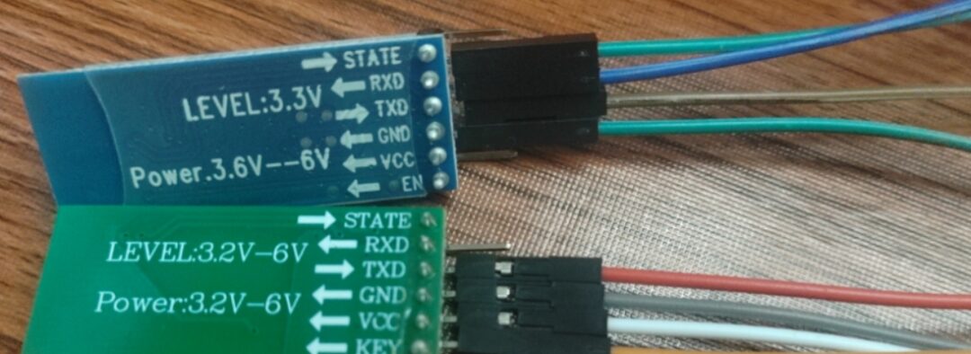
You can use HC-05 (blue in the image below) or HC-08 (green in the image below); both have been tested successfully.
Test the data sent and received using serial port interrupts, and set up serial port remapping:
Remapping code:
int fputc(int ch, FILE *f){ unsigned char temp[1]={ch}; HAL_UART_Transmit(&huart1,temp,1,0xffff); return ch;}Interrupt receiving information code:
// Serial port receive bufferuint8_t buf=0;// Define maximum receive byte number#define UART1_REC_LEN 200// Receive buffer, data received from serial port is stored in this array, maximum UART1_REC_LEN bytesuint8_t UART1_RX_Buffer[UART1_REC_LEN];// Receive status// bit15, receive complete flag// bit14, received 0x0d// bit13~0, number of valid bytes receiveduint16_t UART1_RX_STA=0;#define SIZE 12char buffer[SIZE];// Callback function when receiving is completed, process data herevoid HAL_UART_RxCpltCallback(UART_HandleTypeDef *huart){ // Determine which serial port triggered the interrupt if(huart->Instance == USART1) { // Check if reception is complete (UART1_RX_STA bit15 is 1) if((UART1_RX_STA & 0x8000) == 0) { // If 0x0d (carriage return) is already received if(UART1_RX_STA & 0x4000) { // Then check if 0x0a (newline) is also received if(buf == 0x0a) { // If both 0x0a and 0x0d are received, set bit15 to 1 UART1_RX_STA |= 0x8000; // Control robot movement direction command if(!strcmp(UART1_RX_Buffer, "M1")) { goForward(); printf("goForward success\r\n"); } else if(!strcmp(UART1_RX_Buffer, "M2")) { goBack(); printf("goBack success\r\n"); } else if(!strcmp(UART1_RX_Buffer, "M3")) { goLeft(); printf("goLeft success\r\n"); } else if(!strcmp(UART1_RX_Buffer, "M4")) { goRight(); printf("goRight success\r\n"); } else { if(UART1_RX_Buffer[0] != '\0') { stop(); printf("Received invalid command: %s\r\n", UART1_RX_Buffer); } } memset(UART1_RX_Buffer, 0, UART1_REC_LEN); UART1_RX_STA = 0; } else // Otherwise consider it a reception error, restart UART1_RX_STA = 0; } // If 0x0d (carriage return) has not been received else { // Then check if the received character is 0x0d (carriage return) if(buf == 0x0d) { // If so, set bit14 to 1 UART1_RX_STA |= 0x4000; } else { // Otherwise, store the received data in the buffer array UART1_RX_Buffer[UART1_RX_STA & 0X3FFF] = buf; UART1_RX_STA++; // If received data exceeds UART1_REC_LEN (200 bytes), restart if(UART1_RX_STA > UART1_REC_LEN - 1) UART1_RX_STA = 0; } } } // Restart interrupt HAL_UART_Receive_IT(&huart1, &buf, 1); }}Remember to enable the receive interrupt in the main.c function
// Enable receive interruptHAL_UART_Receive_IT(&huart1, &buf, 1);Open the Bluetooth assistant on your phone and remember to check the “Send New Line” option; otherwise, the interrupt won’t receive data.

Finally, you can control the robot’s movement via the Bluetooth module using your phone: