Abstract: This article introduces a new design method for a LED color light control system, using the AT-89C51 microcontroller as the main control core, combined with minimal auxiliary hardware circuits such as buttons and displays. The system controls LED color lights through software, featuring a compact size, fewer hardware components, a simple circuit structure, and ease of operation.
This paper proposes a color light control scheme based on the AT89C51 microcontroller to control LED color lights. The scheme uses the AT89C51 microcontroller as the main control core, alongside modules for keyboard, display, and drive, forming the core main control module. The main control module is equipped with 8 buttons and a 5-digit seven-segment LED display, allowing users to write various lighting modes. Using its internal timer T0, it implements a basic unit time of 5 ms for timing interrupts. Depending on the different lighting times required, it outputs control signals to turn the lights on or off at different times, driving various colored lights. This new LED color light and its controller were developed as a commissioned product by a company in Shanghai, achieving good practical application effects, with multiple lighting modes that users can adjust based on different occasions and times. Compared with ordinary LED color lights, it has advantages such as a compact size, low cost, and low energy consumption.
2 System Functions
The new LED color light is divided into 2 parts, namely the color light controller (main control module) and the internal LED board module (controlled module). The color light controller can be directly connected to 220 V AC mains, converting through a switch power supply to output DC working voltage, providing 12 V working power to the internal LED module and 5 V working power to the main control module microcontroller (color light controller). The entire system operates under software control, allowing users to set lighting time and flashing frequency through buttons on the main control module while the LED color light is working.
After powering on, the system initializes and checks for any function switch keys pressed: if so, it enters user setting mode; if not, it enters default working status. In user setting mode, users can specify which modes to call based on personal preferences and needs for different occasions, and can change the time Ti and frequency Fi parameters for each mode. If users wish to return to the default mode, they only need to press the function switch key to jump to the default mode, and the program will automatically sequentially call the lighting modes. In default working status, the LED color light controller sequentially calls several lighting pattern programs Model_i set by the program, starting from Model_1, cycling through Model_1 to Model_2… to Model_n for one lighting cycle, then returning to Model_1 to continue working. Similarly, if users wish to enter user setting mode, they only need to press the function switch key. The entire n lighting modes can be seen as a large cycle T, with each lighting pattern working time Model_i (where i=1, 2, …, n) being a small cycle Ti. Each mode has an independent working subroutine Model_i, which defines the lighting moments ( RED_on, GREEN_on, BLUE_on) and extinguishing moments ( RED_off, GREEN_off, BLUE_off) for the three-color LED, as well as the working time Ti and flashing frequency Fi for that mode. The first 2 digits of the 5-digit seven-segment display ( L1, L2) show the current working mode number Model_i; the last 3 digits ( L3, L4, L5) display the working status of the three-color LED. If a color light is on, the corresponding seven-segment display shows “1”; if off, it shows “0”, effectively providing real-time monitoring of the system’s working status.
Thus, after powering on the LED color light, users can conveniently know the current working mode Model_i, working time Ti, frequency Fi, and other real-time parameters through the display on the main control module. If practical applications require changing the flashing effects of the color light based on different occasions and times, users can set different flashing frequencies Fi and lighting times Ti for the LED through buttons on the main control module to meet actual needs. Additionally, if users are interested in a certain mode and wish to observe it closely, they can select any Model_i mode through the keyboard to make the system loop and repeat in that pattern mode.
3 Hardware Design
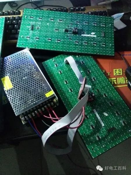
The new LED color light system includes 2 main parts, namely the LED color light controller ( 89C51 main control module) and the LED color light tube (internal LED board module). The former is the main control module, featuring buttons, displays, etc., and uses the 89C51‘s P port to output control signals; the latter is the controlled module, which has three-color LED lights and signal drive chips soldered on, placed within the transparent light tube of the LED.
3.1 Main Control Module Circuit Design
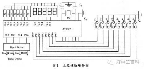
The main control module circuit is shown in Figure 1. The main components of the control module include the 89C51, 5 seven-segment LED displays, 8 buttons, 2 voltage regulators (providing 12 V and 5 V voltages), 1 signal output driver module chip (MC4049), etc. Through software design, the microcontroller’s P0 port serves as the three-color LED driving signal output port and shift clock CLOCK signal, while the P3 port is the button input port, and the P2 and P1 ports connect to the 5-digit seven-segment LED as output ports for the display.
3.2 Internal LED Board Module Design
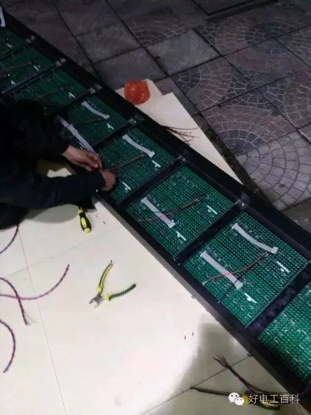
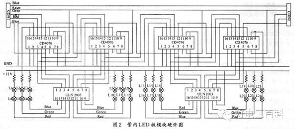
The internal LED board module circuit is shown in Figure 2. The main components of the internal LED board module design include LED color lights (red, green, blue), shift trigger module chip CD4076, etc. Depending on the actual application requirements for the length of the color light, different numbers of these internal LED modules can be cascaded to form a complete LED color light. To consider power loss, the interface between the internal LED board modules is connected using a signal forward drive module chip MC4049. Each internal LED board module evenly distributes 3 colors of LED lights, and during PCB production, a red, green, and blue alternating soldering method is used, with the LED light tubes soldered in order L1(red), L2(green), L3(blue), L4(red), L5(green), L6(blue)… evenly soldered in a straight line. To achieve more pattern effects, the red and green lights can be driven to light up and flash from front to back, while the blue light can be driven to light up and flash from back to front, producing a good dynamic visual effect.
4 Software Design
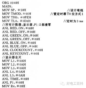
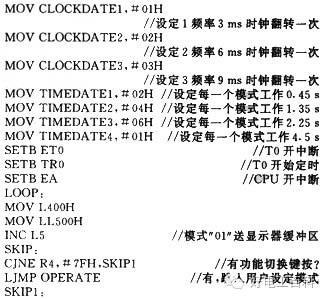
The most significant feature of the new LED color light controller is that all lighting modes are completed by software control. The software in the system can be divided into the main program and interrupt service subroutines. After powering on, in the default state, the main program sequentially calls Model_i lighting modes, with a unit time of 5 ms as the interrupt service subroutine for T0. Based on this 5 ms T0 timing, various mode working times Ti can be determined, as well as the moments for turning on and off various colored LED lights within the different lighting modes Model_i: Red_on, Red_off, Green_on, Green_off, Blue_on, Blue_off, and Clock (shift flip pulse), etc. The entire system software consists of the main program ( Main), various mode subroutines ( Model_i), 5 ms interrupt service subroutine ( T0 Interrupt), keyboard scanning processing subroutine ( Key Board), display subroutine ( Display), and others. Using the T0 timer as the basic timing unit, the occurrence moments of various control signals can be calculated according to the mode needs, and different working times Ti and pulse flip frequencies Fi can be set for different modes Model_i through the P0 port, ensuring that the driving moments of the various colored LED lights are synchronized with the shift trigger flip moments, allowing the LED color light to operate according to the designed patterns.
In addition to T0 timing interrupts, most of the program time is spent handling button queries and LED display delays. The 8 buttons include: 4 parameter buttons ( Fi increase, decrease buttons; Ti increase, decrease buttons), 3 mode change buttons (mode up UP, mode down DOWN, mode hold KEEP), and 1 function switch button. In each T0 timing interrupt service subroutine, it is necessary to increment or clear the various time registers and mode registers to prepare for the main program query while checking if it has interrupted 6 times ( 30 ms). If 30 ms has elapsed, the parameter button queries are performed once to check if the time Ti and frequency Fi increase or decrease buttons are pressed and perform corresponding subroutine processing.
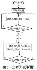
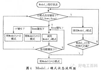
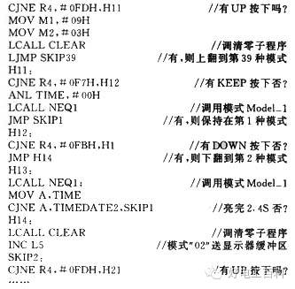
The main program, besides calling various sub-mode subroutines ( Model_i), calling the LED display subroutine ( Display) and delay subroutine ( Delay), also continuously checks if any function switch keys or mode change keys are pressed. Once a function switch key or mode change key is pressed, it will enter the corresponding key processing. The main program flow is illustrated in Figure 3. The lighting mode subroutine Model_i can be written in several ( n types), as long as the triggering and extinguishing moments of each colored light are controlled, various lighting effects can be combined. The Model_i program flow is illustrated in Figure 4.
Below is the example of the first mode in operation.

5 Conclusion
Compared with most LED color lights on the market, this type of color light has better decorative lighting effects and higher cost performance. Compared with ordinary all-hardware LED color lights, it offers better economic benefits. By applying control signals output from the main control module to control the operation of the internal LED board module, the product’s performance is stable, easy to install, and operate. Since the control program is stored in the 89C51 microcontroller’s electrically erasable Flash memory EPROM, if users need to change the lighting mode Model_i, there is no need to alter the system hardware circuits; they only need to modify the program, making it a promising color light controller.

Handsome people have already followed us

Free find work, find masters, find building materials, find orders
Xiamen Construction Network Technology Co., Ltd.
www.168bgt.com
 Long press the QR code to follow the good electrician
If you have any questions, feel free to leave a message below for discussion with the editor.