
Modbus
Introduction
A brand new, customizable Modbus. This is a version you have never seen before. Easy to port and easy to use, with plenty of comments that you will love.
The Modbus protocol is the standard communication protocol for industrial control devices, details can be found in the encyclopedia description. Simply put, the Modbus protocol is designed to allow the master device to access data from slave devices. This repository mainly includes a basic Modbus framework, thus supporting two data types: coils (1 bit) and registers (16 bits) (some Modbus implementations support floating point or 32-bit types). The supported function codes are: 01 read coils, 02 read discrete inputs, 03 read holding registers, 04 read input registers, 05 write single coil, 06 write single register, and 10 write multiple registers.
Software Architecture
This Modbus is implemented based on a state machine framework, thus it has a very fast response speed. However, the state machine does not have its own cache to store information, so additional variables are needed to hold the corresponding data, which means that this framework will occupy more memory than a cached comparison framework.
Installation Tutorial
-
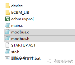
First, prepare a project, it can be a newly created empty project or an old project. Here, we take a new project as an example. Double-click “New Project.bat”, the name can be anything, as long as it is in English. Here we can just write Modbus.
-
Copy modbus.h and modbus.c to the project folder.
-
Open the project, double-click in any project folder, for example, double-click the DEVICE folder, and in the pop-up selection box, double-click modbus.c to add it to the project.
-
Open main.c and load the Modbus header file. As shown in the second line:
#include "ecbm_core.h" // Load the library function header file.#include "modbus.h" // Load the Modbus header file.void main(){ // Main function, mandatory. system_init(); // System initialization function, also mandatory. while(1){ }}At this point, the Modbus component has been completely added to the project. However, just adding it to the project does not allow the use of Modbus. Modbus is a serial-based protocol, so we also need to initialize the serial port.
-
Fortunately, ECBM defaults to opening the serial port, first go to ecbm_core.h to set the current microcontroller model. Of course, when setting, don’t forget to use ECBM’s powerful graphical configuration interface, just click the [Configuration Wizard] tab at the bottom left of the window. For the instance microcontroller, I use STC8F2K32S2, so follow the steps shown in the figure to set it. Make sure the microcontroller clock setting is [Internal High-Speed Clock HSI (Standard)], this way the ECBM library will automatically recognize the clock frequency you set in the stc-isp tool. With this automatic recognition, you won’t miss data due to incorrect clock settings or baud rates. Then make sure the [Automatic Download Function] is enabled, as this will make your debugging more convenient and will automatically initialize the serial port once enabled, saving trouble.
-
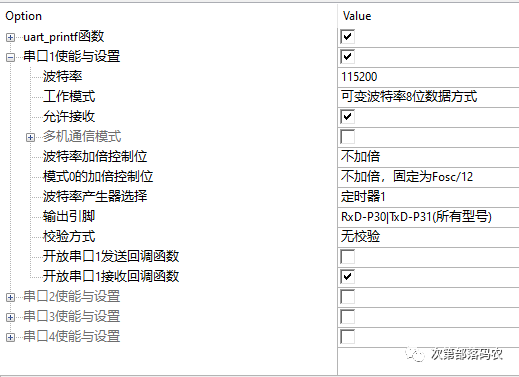
Open uart.h and enter the graphical configuration interface. Change the baud rate to the actual baud rate used, such as 115200. Enable reception and open the reception callback function for serial port 1.
-
In main.c, define the serial port 1 callback function, named uart1_receive_callback. Then place the Modbus receive function into the serial port 1 callback function. Next, define two functions for Modbus read and write serial ports, ecbm_modbus_rtu_set_data and ecbm_modbus_rtu_get_data.
#include "ecbm_core.h" // Load the library function header file.#include "modbus.h" // Load the Modbus header file.void main(){ // Main function, mandatory. system_init(); // System initialization function, also mandatory. while(1){ }}void uart1_receive_callback(void){// Receive handling part. ecbm_modbus_rtu_receive();}void ecbm_modbus_rtu_set_data(emu8 dat){// Sending data part. uart_char(1,dat);// ECBM library's sending function.}emu8 ecbm_modbus_rtu_get_data(void){// Getting serial port value part. return SBUF;// Serial port 1's register} -
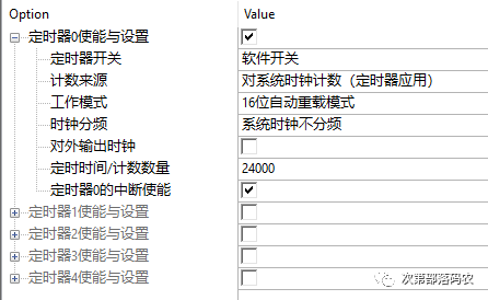
Modbus also has a reception timeout setting, so a timer is needed for assistance. Open timer.h and enter the graphical settings interface, choose any timer, for example, timer 0. Set it to timer mode, then set the timing to 1mS. Since the microcontroller operates at 24MHz on the experimental platform, the initial value for 1mS is 24000.
-
Return to main.c, add code to initialize the timer and run the timer. Finally, just write the Modbus running function into the loop. At this point, Modbus has been installed and can be used.
#include "ecbm_core.h" // Load the library function header file.#include "modbus.h" // Load the Modbus header file.void main(){ // Main function, mandatory. system_init(); // System initialization function, also mandatory. timer_init(); // Initialize timer. timer_start(0); // Start timer 0. while(1){ ecbm_modbus_rtu_run();// Run Modbus function. }}void uart1_receive_callback(void){// Receive handling part. ecbm_modbus_rtu_receive();}void ecbm_modbus_rtu_set_data(emu8 dat){// Sending data part. uart_char(1,dat);// ECBM library's sending function.}emu8 ecbm_modbus_rtu_get_data(void){// Getting serial port value part. return SBUF;// Serial port 1's register}void tim0_fun(void)TIMER0_IT_NUM {// Timer handling part ECBM_MODBUS_RTU_TIMEOUT_RUN();}
Usage Instructions
Modbus is a serial communication protocol used for computers to access device registers to complete settings or perform certain actions. Its fixed data format is: 【Device Address】 + 【Function Code】 + 【Starting Address】 + 【Function Code Related】 + 【CRC Check】. This library currently supports 7 function codes: 01, 02, 03, 04, 05, 06, and 10.
Function Code Details
【01】 Read Coils
| Device Address | Function Code | Starting Address | Coil Count | CRC |
|---|---|---|---|---|
| 1~247 | 01 | 0x0000~0xFFFF | 1~2000 | Low byte first, high byte later |
Example: The master sends 【01 01 00 00 00 01 FD CA】. This means to read the value of coil number 0000 in the device with address 01.
【02】 Read Discrete Inputs
| Device Address | Function Code | Starting Address | Coil Count | CRC |
|---|---|---|---|---|
| 1~247 | 02 | 0x0000~0xFFFF | 1~2000 | Low byte first, high byte later |
Example: The master sends 【01 02 00 00 00 03 38 0B】. This means to read the values of 3 discrete inputs from address 01 in the device from 0000 to 0002.
【03】 Read Holding Registers
| Device Address | Function Code | Starting Address | Register Count | CRC |
|---|---|---|---|---|
| 1~247 | 03 | 0x0000~0xFFFF | 1~125 | Low byte first, high byte later |
Example: The master sends 【01 03 00 0A 00 03 25 C9】. This means to read the values of 3 registers from address 01 in the device from 000A to 000C.
【04】 Read Input Registers
| Device Address | Function Code | Starting Address | Register Count | CRC |
|---|---|---|---|---|
| 1~247 | 04 | 0x0000~0xFFFF | 1~125 | Low byte first, high byte later |
Example: The master sends 【01 04 00 00 00 01 31 CA】. This means to read the value of input register number 0000 in the device with address 01.
【05】 Write Single Coil
| Device Address | Function Code | Starting Address | Coil Count | CRC |
|---|---|---|---|---|
| 1~247 | 05 | 0x0000~0xFFFF | 0x0000 or 0xFF00 | Low byte first, high byte later |
Example: The master sends 【01 05 00 0A FF 00 AC 38】. This means to set the value of coil number 000A in the device with address 01 to 1.
【06】 Write Single Register
| Device Address | Function Code | Starting Address | Register Value | CRC |
|---|---|---|---|---|
| 1~247 | 06 | 0x0000~0xFFFF | 0x0000~0xFFFF | Low byte first, high byte later |
Example: The master sends 【01 06 00 01 12 34 D5 7D】. This means to set the value of register number 0001 in the device with address 01 to 0x1234.
【10】 Write Multiple Registers
| Device Address | Function Code | Starting Address | Register Count | Byte Count | Register Value | CRC |
|---|---|---|---|---|---|---|
| 1~247 | 10 | 0x0000~0xFFFF | 1~78 | Number of registers * 2 | 0x0000~0xFFFF | Low byte first, high byte later |
Example: The master sends 【01 10 00 0A 00 04 08 11 11 22 22 33 33 44 44 5D 5E】. This means to set the values of 4 registers from address 01 in the device from 000A to 000D to 0x1111, 0x2222, 0x3333, and 0x4444 respectively.
How to Customize Modbus Registers
To facilitate use, this library defaults to including two arrays as registers in Modbus communication. Among them:
-
ecbm_modbus_rtu_bit_buf, used to store coil operations. That is, function code 01 will read data from this array, and function code 05 will write data to this array.
-
ecbm_modbus_rtu_reg_buf, used to store register operations. That is, function code 03 can read data from this array, and function code 06 will write data to this array. Function code 10 can write multiple data to the array at once.
However, if you need this library to interface with an old project, or if your project is more complex and not just simple register storage, you can disable the built-in arrays and define new read and write functions instead.
For example, if you don’t need the built-in coil cache, the first step is to disable the coil cache enable. 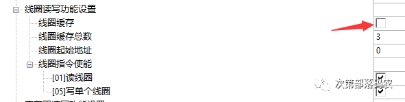
The second step is to rebuild the coil read and write functions. Since the original read and write functions operate on the built-in cache, they will become invalid after disabling the cache. Rebuilding is very simple, just define an ecbm_modbus_cmd_write_bit function and an ecbm_modbus_cmd_read_bit function. Here’s an example:
void ecbm_modbus_cmd_write_bit(emu16 addr,emu8 dat){ if(addr==101){// For example, address 101 corresponds to the status of the manager LED. if(dat==0){// If 0 is written to 101, LED_OFF;// Turn off the LED. }else{// Otherwise LED_ON;// Turn on the LED. } } if(addr==0){// For example, address 0 corresponds to the DCDC enable on the board. dc_dc_en=dat;// Assign the written data to enable. }}void ecbm_modbus_cmd_read_bit(emu16 addr,emu8 * dat){ if(addr==101){// For example, address 101 corresponds to the status of the manager LED. if(LED_PIN==0){// If this pin is low, it means the LED is on. *dat=1;// Note, the reason for returning 1 here is that usually the LED is lit with a low level. }else{// Otherwise *dat=0;// Return 0. } } if(addr==0){// For example, address 0 corresponds to the DCDC enable on the board. *dat=dc_dc_en;// Return the enable status. }}
Similarly, if you do not need the built-in register cache, it can also be done in two steps. The first step is to disable the register cache enable. 
The second step is to rebuild the register read and write functions, for the same reason. They are ecbm_modbus_cmd_write_reg and ecbm_modbus_cmd_read_reg. Here’s an example:
void ecbm_modbus_cmd_write_reg(emu16 addr,emu16 dat){ if(addr<512){// You can use addresses below 512 as the OLED cache (128*64 points require 128x64/16=512 16-bit registers). OLED_BUF[addr]=dat; }else{// Addresses above 512 are used for another group. MCU_SETTING[addr-512]=dat; if(addr==512){// When the address is 512, if(dat&0x0001){// When written 1, define that the user wants to update the OLED. OLED_SHOW();// Refresh the OLED display. } }} }void ecbm_modbus_cmd_read_reg(emu16 addr,emu16 * dat){ if(addr<512){// You can use addresses below 512 as the OLED cache (128*64 points require 128x64/16=512 16-bit registers). *dat=OLED_BUF[addr]; }else{// Addresses above 512 are used for another group. *dat=MCU_SETTING[addr-512]; }}As you can see, the customized Modbus registers can not only perform ordinary storage functions but also have some triggering functions, allowing the microcontroller to perform certain actions through issued commands. This will greatly expand the usage scenarios of Modbus.
Graphical Configuration Interface Explanation
As we all know, the graphical configuration interface is a feature of the ECBM series, and naturally, this Modbus library is no exception. 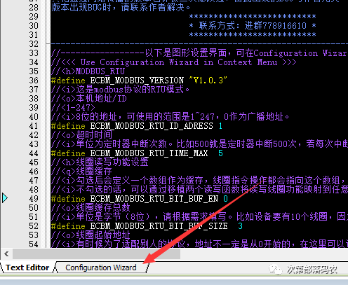
First, open modbus.h with Keil, find the Configuration Wizard tab at the bottom left. Click to enter the graphical configuration interface. This interface is a feature of Keil, so it cannot be enjoyed with IAR and GCC. 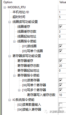
Now I will explain each part:
Local Address/ID
As the name suggests, this is a unique address established in the bus to distinguish different devices. During use, ensure that this address is unique; otherwise, there will be conflicts on the bus. Since the information set in the graphical configuration interface cannot be modified after compilation, to achieve a dynamic ID address, you can modify the variable ecbm_modbus_rtu_id.
Timeout
In serial communication, communication interruptions may occur. Since Modbus-RTU uses raw data transmission, meaning that 0x00 to 0xFF can be used to represent data, there is no value that can be specifically used as frame headers or footers. In this respect, Modbus-ASCII does well, as it only uses characters 0 to 9 and A to F to represent data, using a colon to indicate the frame header, allowing for easy determination of the start and end of a data frame. Since Modbus-RTU cannot operate this way, to allow the Modbus slave to return to a waiting state after a communication interruption, a timeout period needs to be set. The value set in the graphical configuration interface represents the number of times ECBM_MODBUS_RTU_TIMEOUT_RUN is executed. For example, if it is set to 5 and ECBM_MODBUS_RTU_TIMEOUT_RUN runs every 10mS, then if no serial data is received for more than 5*10=50mS, it is considered a communication interruption, and Modbus will return to the waiting state.
Coil Read/Write Function Settings
The concept of coils comes from older industrial equipment, where a coil refers to a relay, which can typically output high or low levels, so in simple terms, a coil is a bit register that can store a bit of information.
Coil Cache
This cache is actually a u8 type array, and since a coil is a bit of data, using one byte to store one bit is too wasteful of space. To facilitate users in storing bit data in a u8 type array, this library has already written this algorithm. When this option is enabled, this library will define an array ecbm_modbus_rtu_bit_buf, and will also define the corresponding read and write functions ecbm_modbus_cmd_write_bit and ecbm_modbus_cmd_read_bit. By calling the read and write functions, you can read and write the corresponding coils. If this library is ported to an older project, that is, if there is already a cache in the original project, then you can disable this option. If you do not enable it, the array ecbm_modbus_rtu_bit_buf will not be defined, and you will need to write the read and write functions yourself, as the author cannot anticipate what cache your old project uses.
Total Number of Coils Cached
This setting involves the address and total number of data in Modbus communication, so regardless of whether the above 【Coil Cache】 is enabled or not, this option cannot be filled in arbitrarily; it must be filled in according to the actual situation. The unit of the value is bytes; if you need 10 coils, you need two bytes to hold them, so you should fill in 2.
Starting Address of Coils
This is for special requirements; for most users, keeping it at 0 is fine.
Coil Command Enable
This mainly involves two commands: one for reading coils (01) and one for writing coils (05). Enabling the corresponding commands allows this library to compile the corresponding command parsing code. Therefore, if there is a need, you can enable it; if there is no need, you can disable it to save program space.
Register Read/Write Function Settings
The concept of registers is easier to understand than coils, as it is similar to the registers in microcontrollers, and the Modbus registers are 16 bits.
Register Cache
As with coils, to facilitate users, the read and write algorithms have been written. Enabling the cache will define a u16 type array ecbm_modbus_rtu_reg_buf and the read and write functions ecbm_modbus_cmd_write_reg and ecbm_modbus_cmd_read_reg. If it is ported to an old project or if you want to customize read and write functions, do not enable this option, and then you can define the read and write functions yourself.
Total Number of Registers Cached
This parameter is not only used to define the cache array but also involves Modbus communication’s address and total transmission count judgment, so regardless of whether the register cache is enabled or not, this option should be filled in according to the actual situation. Since u16 type can be directly defined, the unit for this option is words (1 byte = 8 bits, 1 word = 16 bits). Fill in as many as needed.
Starting Address of Registers
This is for special requirements; for most users, keeping it at 0 is fine.
Register Command Enable
This mainly involves three commands: one for reading registers (03), and two for writing registers (06 and 10). Command 06 can only write one register at a time. Command 10 can write multiple registers at once. Enabling the corresponding commands allows this library to compile the corresponding command parsing code. Therefore, if there is a need, you can enable it; if there is no need, you can disable it to save program space. Additionally, for command 10, there is an option for defining the total size of the write cache, as Modbus communication requires CRC calculation. If the CRC is incorrect, all information transmitted this time will be discarded. Therefore, before the CRC result comes out, the data being sent will be placed in the write cache. This option defines the size of this cache, and the unit is also words (16 bits). If the definition of the write cache is 10, and 15 is actually transmitted, it will cause a problem due to data overflow, so be careful to ensure it meets the actual situation.
IO System Command Enable
This includes two commands: one is command 02 for reading discrete inputs, and the other is command 04 for reading input registers. Since external inputs can vary greatly, the corresponding functions for these two commands have not been defined. If needed, enable them first and then define the corresponding read functions. Command 02 corresponds to the function ecbm_modbus_cmd_read_io_bit, and command 04 corresponds to ecbm_modbus_cmd_read_io_reg.
Source code download: https://gitee.com/ecbm/modbus.git