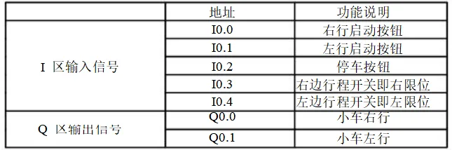
Wiring Diagram for Car Back-and-Forth Movement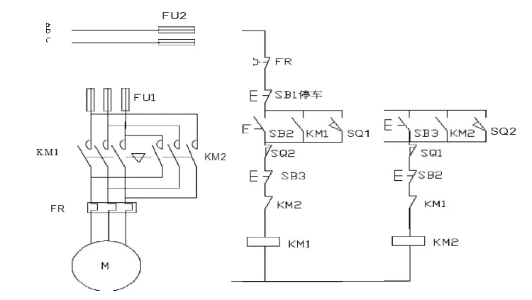 I/O Allocation Table
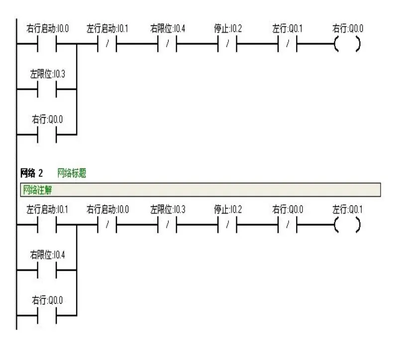
 Ladder Diagram Program
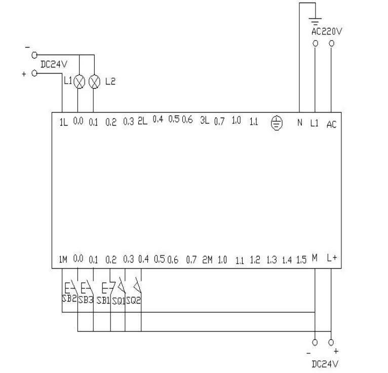
 PLC Wiring Diagram
 Program Debugging and Result Analysis
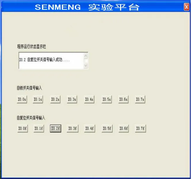 Control Platform Operation PanelPress SB2 (click i0.0f) to connect I0.0, then Q0.0 outputs, and the car moves to the right (corresponding indicator Q0.0 lights up);When the car touches the right limit switch SQ2 (click i0.4f to simulate pressing), I0.4 connects, and the car switches to move left (Q0.0 off, Q0.1 on);When the car touches the left limit switch SQ1 (click i0.3f to simulate pressing), I0.3 connects, and the car moves right again (Q0.1 off, Q0.0 on);The above back-and-forth movement continues until SB1 is pressed (click i0.2f) to connect I0.2, stopping the car.Appendix
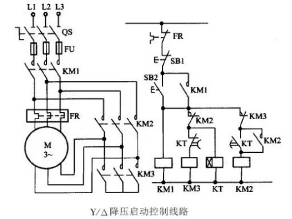
 Star-Delta Starting S7-200 PLC Control Diagram
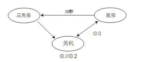
 Process Framework
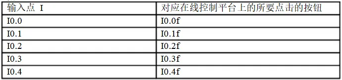
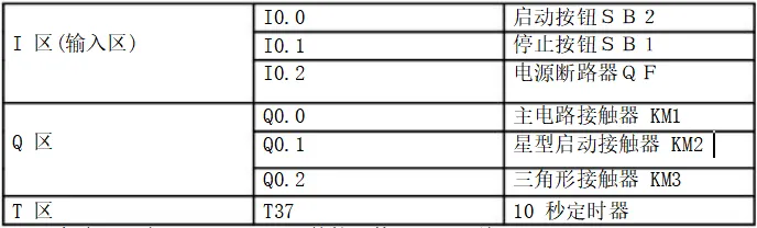
 I/O Allocation Table
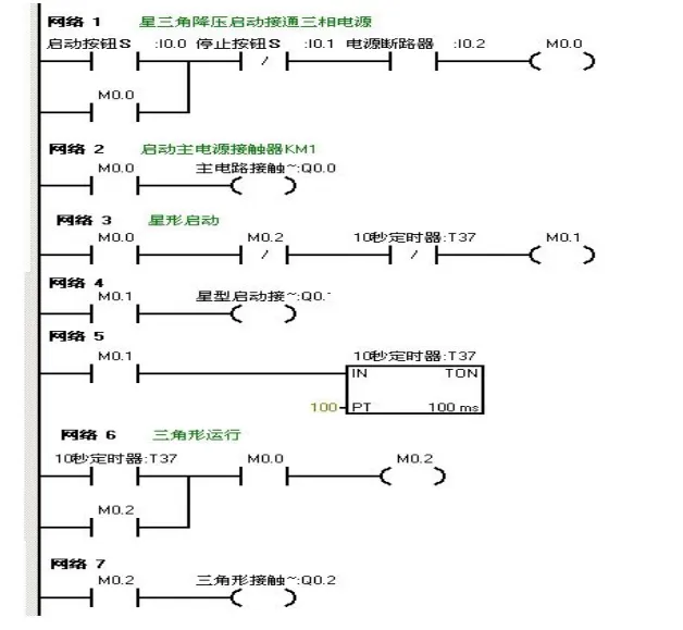
 Ladder Diagram Program
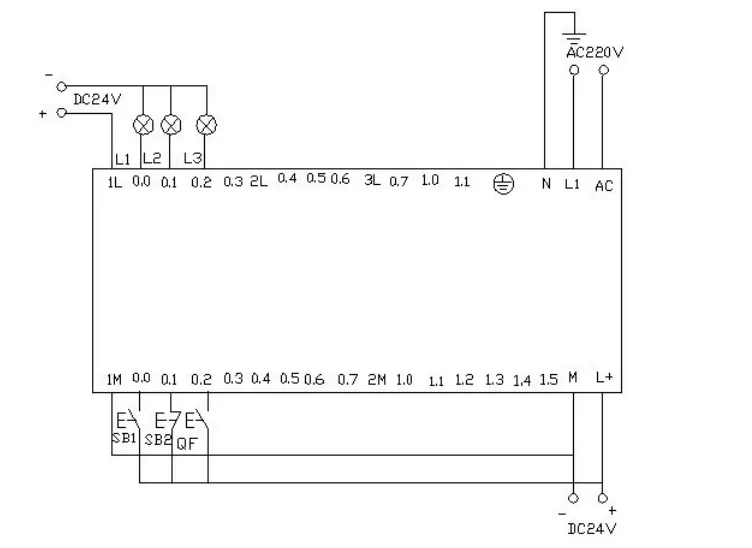
 PLC Wiring Diagram
 Program Debugging Result Analysis
After downloading the written program to the Siemens S7-200 PLC, use the online control panel for debugging to verify if the running results meet expectations:
1. First, set I0.2 on the control panel (simulating button press), connecting I0.2, representing the circuit breaker QF closing;
2. Press the start button I0.0 (simulating SB2 pressed), I0.0 connects, and the motor enters star starting mode: Q0.0, Q0.1 outputs, corresponding to L1, L2 lights in the experimental wiring diagram, while the timer starts counting;3. After 10 seconds, it automatically switches to delta operation: Q0.1 stops output, Q0.2 starts output, while Q0.0, Q0.2 maintain output, corresponding to L1, L3 lights on the wiring panel;4. Press I0.1 on the online panel (simulating stop operation), I0.1 connects, and the motor stops running, with all output points off.Color Light Control
Using the eight output terminals Q0.0 to Q0.7 of the PLC to control eight color lights, making each light turn on every second in a loop. When I0.0 is connected, all lights turn off. When I0.1 is connected, it starts looping again from Q0.0.
I/O Allocation Table Ladder Diagram Program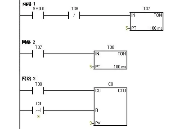
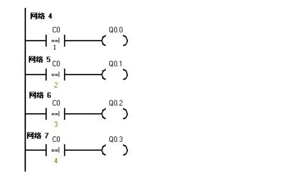
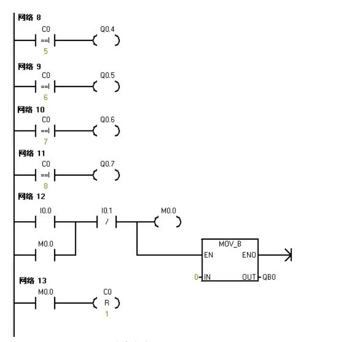
PLC Wiring Diagram:
 Program Debugging Result Analysis
Download the program to the PLC for debugging: After downloading, open the online control panel to verify if the running results meet expectations.
After powering the PLC, SM0.0 remains connected, and T37 starts timing; after T37 times out, T38 starts timing, and when T38 times out, its normally closed contact opens, stopping T37, while T37’s normally open contact resets, stopping T38.
Then T38’s normally closed contact resets, T37 starts timing again, while counter C0 counts once, and this process repeats.
During counting: When C0 counts 1, Q0.0 connects; when 2, Q0.1 connects… When it counts to 8, Q0.7 connects; when it counts to 9, C0 automatically resets.
When operating the online control panel: Press I0.0f (I0.0 connects), counter C0 and Q0.0~Q0.7 all reset, all indicator lights turn off; press I0.1f (I0.1 connects), counter starts counting again, and the indicator lights light up sequentially from Q0.0.
8 Color Light Shift Control
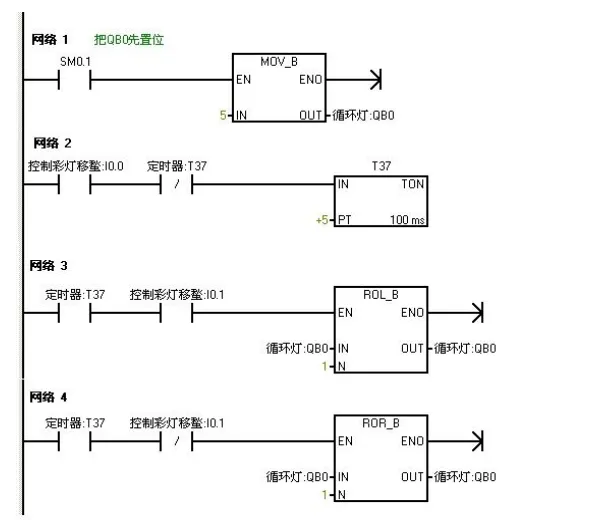
Control the eight color lights connected to Q0.0 to Q0.7 to shift in a loop using IO wires, with T37 timing, shifting every 0.5 seconds. Initially set Q0.0 to Q0.7 to have outputs for Q0.0 and Q0.2. Use I0.1 to control the direction of the color light shift.
I/O Allocation Table Ladder Diagram Programming
 PLC Wiring Diagram
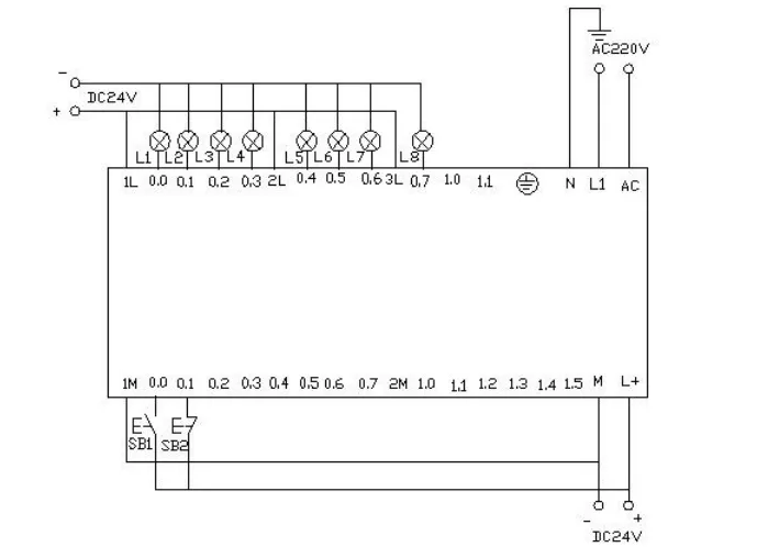 Program Debugging Result Analysis
Download the program to the Siemens S7-200 PLC for debugging: After powering the PLC, Q0.0 and Q0.2 directly output (corresponding indicator lights on)
When operating the online panel:
1. Press I0.0f (I0.0 connects), timer T37 starts, and every 0.5 seconds, the color lights shift right from Q0.0, Q0.2 as the initial state;
2. Press I0.1f (I0.1 connects), the color lights shift left in the same manner.Disclaimer | This article is sourced from Electrical Engineering Learning, and the purpose of reprinting is to convey more information and share. If there is any infringement, please contact this platform immediately for resolution!