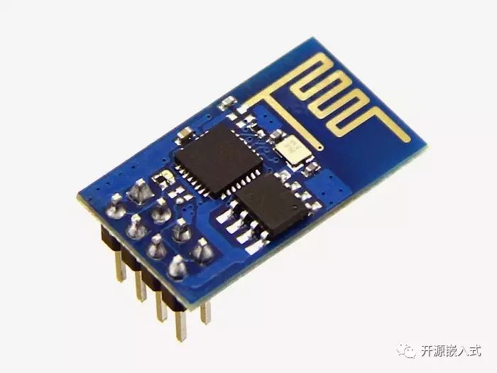
The ESP8266 is an ultra-low-power UART-WiFi transparent transmission module, featuring highly competitive packaging size and ultra-low energy consumption technology. It is designed specifically for mobile devices and Internet of Things applications, allowing users’ physical devices to connect to Wi-Fi wireless networks for internet or local area network communication, thus achieving networking functionality.
Although the “WiFi door lock” has been delayed, the WiFi module has been in use for a long time. It’s time to introduce the basic usage and configuration of the ESP8266.
Content Overview
Connecting hardware to the internet has always been a bit troublesome, but by using the ESP8266 WiFi module, most network functionality requirements can be met simply by controlling it with AT commands via the serial port. This article provides a simple introduction and application examples to help readers who are new to WiFi modules understand the general usage of the module.
Introduction to ESP8266
The ESP8266 is a low-power WiFi chip designed by Espressif Systems, integrating a complete TCP/IP protocol stack and MCU. The ESP8266 module is a serial WiFi module developed by Shenzhen Anxinke based on the ESP8266 chip (adding necessary peripheral circuits, serial flash, onboard antenna, etc.) with low cost, ease of use, and powerful functionality.
Bridge Between Hardware and Network
Like serial Bluetooth modules, serial WiFi modules are another magical tool for extending microcontroller functionality. Before I encountered the 8266, I was very curious about how microcontrollers connect to the internet. I had seen cumbersome and complicated Ethernet modules in books, but they weren’t appealing at all. The compact ESP8266 WiFi module communicates with the microcontroller through serial AT commands, achieving serial transparent transmission, making it very easy to use.
Transparent transmission, also known as transparent transmission, specifically means “input equals output” (for example, characters input from the WiFi module’s serial port will be transmitted to the server). The data remains unchanged, and the conversion between different protocols (such as serial to WiFi, Bluetooth, etc.) is completed by the module. Users do not need to care about the internal implementation, so the module is “transparent” to users, seemingly non-existent (as they can ignore the underlying implementation principles). A highly encapsulated module should hide internal implementation details and only provide an external interface for use.
Once hardware is connected to the internet, it is no longer just “playing single-player”. Combined with server-side socket network programming, many things can be achieved. Therefore, I believe the WiFi module serves as a bridge between software (network programming) and hardware (microcontrollers), linking my knowledge of microcontrollers and web technologies.
Recently, the “Internet of Things” or “smart hardware” seems to have gained popularity, with many powerful chips and modules emerging, significantly lowering the development threshold for connected devices. Thanks to the various manufacturers paving the way for the Internet of Things, even those of us who know little about networking can easily connect hardware and achieve network communication.
Module Information
When purchasing a module on certain platforms, there are generally corresponding documentation covering usage methods and common issues.
Preparation Before Starting
Schematic and Pin Description
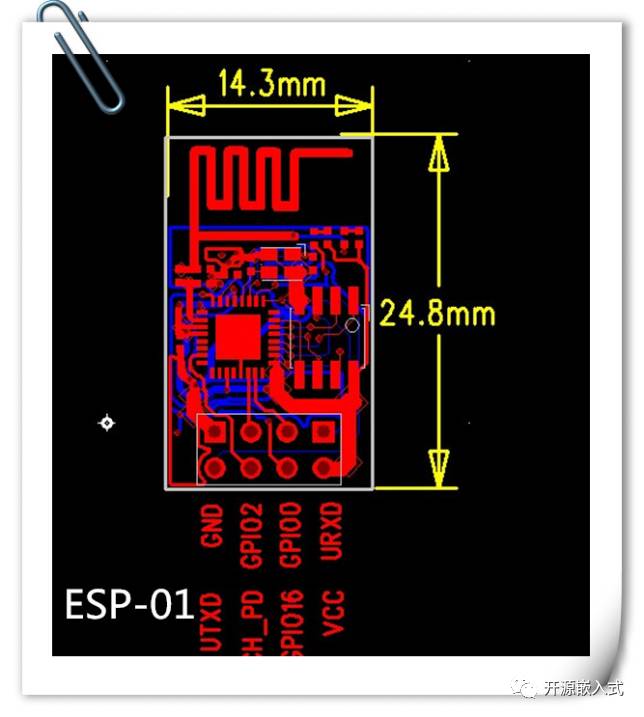
| Function | Description |
|---|---|
| URXD | UART_RXD, Receive |
| UTXD | UART_TXD, Transmit |
| GPIO 16 | External Reset Signal, Low Level Reset, High Level Work (Default High) |
| GND | GND |
| VCC | 3.3V, Module Power Supply |
| GPIO 0 | Work Mode Selection: Floating: FlashBoot, Working Mode; Pulled Down: UART Download, Download Mode |
| CH_PD | High Level Work; Low Level Turns Off Module Power |
| GPIO 2 | (1) Must be high when powered on, hardware pull-down is prohibited; (2) Internal default is pulled high |
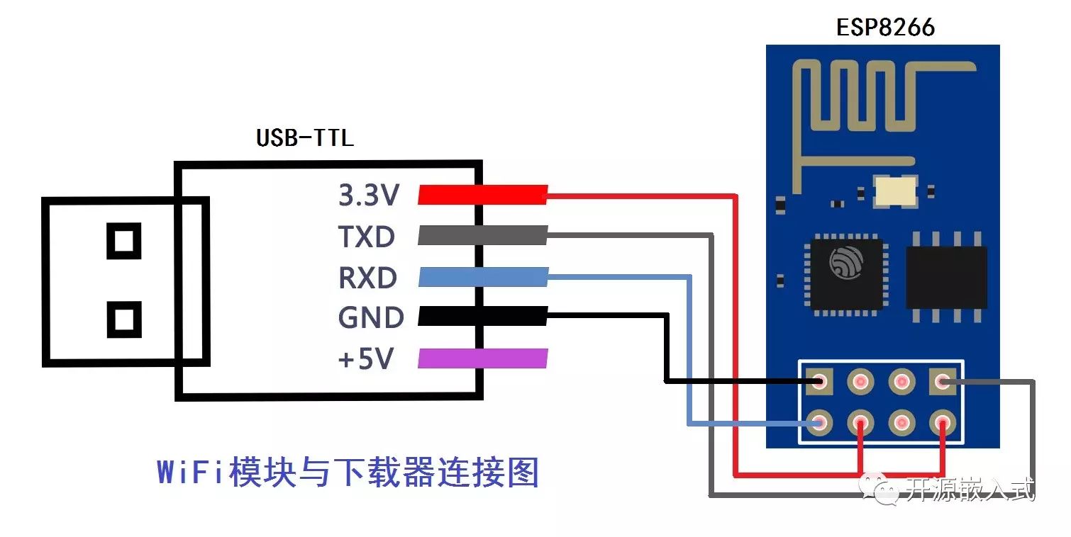
Wiring the Module
To power the module and ensure it works properly, only three connections are needed: VCC and CH_PD connected to the positive terminal of the 3.3V power supply, and GND connected to ground. The USB-TTL download module conveniently provides a 3.3V power supply. For serial debugging, the module needs to be cross-connected with the downloader’s TXD and RXD. This way, the WiFi module can connect to the computer and be tested using a serial assistant.
Powering the Module
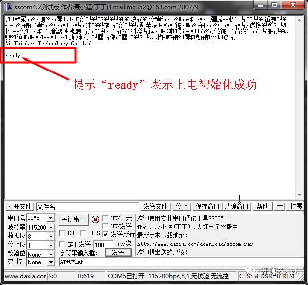
After installing the USB-TTL module driver on the computer, plug the module into the USB port, check the serial port number in the device manager, open the serial debugging tool SSCOM, select the corresponding serial port number for the module, set the default baud rate to 115200, and configure data-stop-check-flow control: 8-1-None-None. Make sure to check “Send New Line” (It is crucial to remember to check “Send New Line”, otherwise the WiFi will not recognize AT commands), click the “Open Serial Port” button, then disconnect and reconnect the 3.3V power supply to the CH_PD pin to reset. If the serial prints garbled characters and then shows “ready”, it indicates that the module has initialized properly.
Unlike some Bluetooth modules that require a button to enter AT command mode, the ESP8266 runs in AT command mode upon power-up.
Pitfalls of Cold Boot-Free Downloaders
I remember once, when using the ESP8266 in the lab, I couldn’t successfully power it up and initialize it to display “ready”; AT commands were also unresponsive. I ended up flashing the firmware repeatedly, damaging the module without success, it felt like encountering a ghost… Eventually, it turned out to be due to using a cold boot-free downloader. I later learned that the ESP8266 has very strict power supply requirements, which must be “stable and pure”. I suspect that this “advanced downloader” has internal circuitry that causes unstable power supply during module power-up, leading to initialization failure. If you encounter a similar problem, try using a different USB-TTL downloader.
Don’t underestimate the possibility of strange bugs being caused by some inconspicuous hardware; this can be quite “mystical”.
AT Commands for ESP8266
I first encountered AT commands on Bluetooth modules. The so-called AT commands are essentially special strings that serve control functions. The module can be controlled using AT commands or developed using source code API functions; the former is faster and much easier (user-friendly), while the latter is flexible but more complex. Since I have only used AT commands, this article does not cover SDK development.
Note: Below are some of the most commonly used AT commands and their usage. For detailed parameters and usage instructions, please refer to the official documentation: ESP8266 AT Command Set.
Basic AT Commands
| Command | Description |
|---|---|
| AT | Test AT startup |
| AT+RST | Restart the module |
| AT+GMR | View version information |
AT is the most commonly used command to test whether the module can accept commands normally. Sending the command AT to the serial port in SSCOM, if the module returns OK, it indicates that the AT commands are functioning properly. Sending AT+GMR retrieves the version number of the AT commands and SDK; the current version I am using is the latest version V1.1.0.0, which generally includes new features, so you can always keep an eye on the official updates.
WiFi Function AT Commands
WiFi is fundamental for connecting hardware to the internet. Like other functionalities, here are the commonly required commands; more detailed command descriptions should be consulted in the documentation.
| Command | Description |
|---|---|
| AT+CWMODE | Set WiFi mode (sta/AP/sta+AP) |
| AT+CWLAP | Scan for nearby AP information |
| AT+CWJAP | Connect to AP |
| AT+CWQAP | Disconnect from AP |
| AT+CWSAP | Set ESP8266 softAP configuration |
| AT+CWLIF | Get information about stations connected to ESP8266 softAP |
Regarding the WiFi mode, it’s important to note that in sta mode, the module acts as a client, similar to our smartphones and tablets that connect to a router, while in AP mode, the module acts as a router, broadcasting WiFi for others to connect. The ESP8266 supports both modes simultaneously (the default factory setting is AP mode). Additionally, the scanning WiFi command AT+CWLAP can only be used in sta mode; otherwise, it will return an ERROR. The same applies to AT+CWJAP and AT+CWQAP commands.
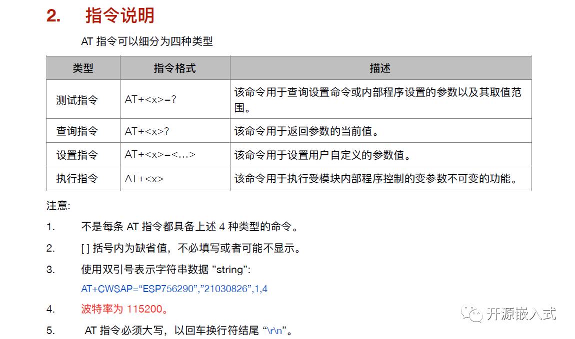
Demonstration of Connecting WiFi in sta Mode
How do we get the module to connect to the router? Here are the simple steps:
-
Send the command
AT+CWMODE=1to configure the module in sta mode (parameters 1, 2, and 3 correspond to modes sta, AP, and sta/AP respectively). -
Send the command
AT+CWLAPto scan for nearby WiFi; the module will return a list of available APs. -
Use the command
AT+CWJAP="WiFi Name","WiFi Password"to connect to a specific router. For instance, my library’s WiFi is “lib-free-wlan01”, and the password is “zhku-lib”; the actual command to connect isAT+CWJAP="lib-free-wlan01","zhku-lib". -
The returned “WIFI CONNECTED” indicates a successful connection, while “WIFI GOT IP” means the module has been assigned an IP address.
-
Finally, you can use
AT+CWQAPto disconnect from the currently connected WiFi.
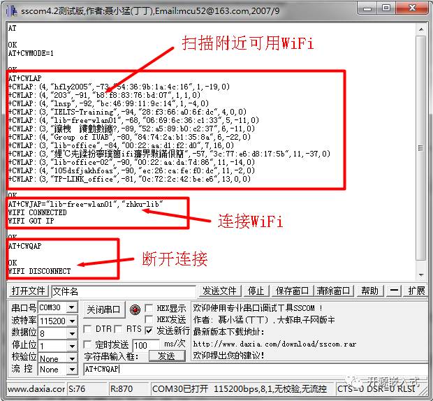
Demonstration of AP Mode Parameter Settings
After connecting to WiFi, let’s “turn on WiFi”! Setting up AP mode is just like enabling a hotspot on a smartphone; you only need to set the WiFi name and password. First, use the command AT+CWMODE=2 to configure the module in AP mode, then send AT+CWSAP="ESP8266","12345678",3,4 to set the AP’s SSID to “ESP8266”, password to 12345678, where the last two parameters 3 and 4 represent the channel and encryption method, respectively. After connecting to the module’s WiFi with your phone, you can use AT+CWLIF to view the list of clients currently connected to the AP.
TCP/IP Related AT Commands
Transmission Control Protocol (TCP) is a connection-oriented, reliable, byte stream-based transport layer communication protocol defined by IETF RFC 793. In the simplified OSI model of computer networks, it performs functions specified at the transport layer. The User Datagram Protocol (UDP) is another important transport protocol at the same layer.
In the Internet protocol suite, the TCP layer sits above the IP layer and below the application layer. Applications on different hosts often require a reliable, pipe-like connection, but the IP layer does not provide such a flow mechanism; instead, it offers unreliable packet switching. — Wikipedia
When we talk about the internet, how do two devices connected to the internet “communicate”? TCP connections are one of the most commonly used methods. TCP is a connection-oriented transport layer protocol, and both parties must implement the TCP protocol. One party only needs the target IP address and port number to initiate a connection; once established, it is like pulling a pipe between the two parties, allowing full-duplex (simultaneous two-way) communication.
TCP is a transport layer protocol encapsulated based on the network layer IP protocol. The implementation details of these encapsulations are not our concern; we just need to use the relevant interfaces provided by the system as “plug and play”, such as sockets in network programming. The ESP8266 module also implements the TCP/IP protocol stack, allowing the module to easily initiate a TCP connection to the server using AT commands. Once the TCP server connection is established and transparent transmission mode is enabled, the data received by the module’s serial port will be transmitted to the server through the TCP connection, thus completing the transmission of data from the hardware serial port through the network to the program process, achieving the integration of software and hardware.
| Command | Description |
|---|---|
| AT+CIPSTATUS | Query network connection information |
| AT+CIPMUX | Set multi-connection mode |
| AT+CIPSTART | Establish TCP connection, UDP transmission, or SSL connection |
| AT+CIPCLOSE | Close TCP/UDP/SSL transmission |
| AT+CIPMODE | Set transparent transmission mode |
| AT+CIPSEND | Send data |
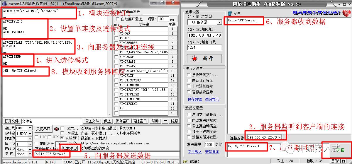
Demonstration of TCP Network Communication Between WiFi Module and Server in Transparent Mode
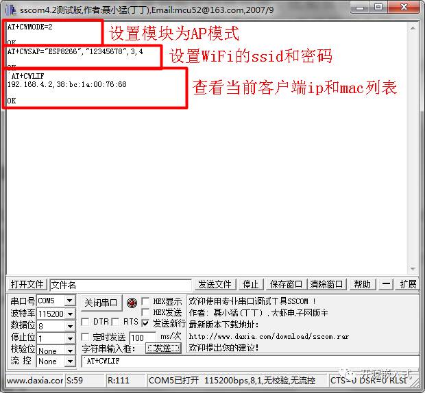
Talking about it is not as good as experiencing it hands-on; let’s see how to connect the WiFi module to a TCP server and understand the specific usage of TCP/IP-related AT commands. First, we need a TCP server, which can be created using the debugging tool “Network Debug Assistant” (the software is included in the documentation package), allowing the server to listen for TCP connection requests on a specified port. Of course, you can also write a program to achieve this, but for simplicity, we’ll use the existing tool.
Open the “Network Debug Assistant”, select “TCP Server” on the left side, enter a custom port number (1024-65535), and click the “Connect” button to start listening for TCP connection requests from the local machine. Before proceeding, ensure that both the computer and the WiFi module are connected to the same router.
Connect the WiFi module to the computer, and after confirming that the AT commands are functioning properly in SSCOM, you can start configuring the TCP connection. The specific steps are as follows:
-
Connect the module to WiFi as shown in the previous “Demonstration of Connecting WiFi in sta Mode” section.
-
Input the command
AT+CIPMUX=0to set single connection mode. -
Using the information from the “Network Debug Assistant” about the local IP and port, input the command
AT+CIPSTART="TCP","192.168.43.140",1234(the command parameters are connection type, target IP address, and port number) to initiate a TCP connection request to the server. Once the handshake is successful and the connection is established, the server-side “Network Debug Assistant” will display the client IP and port information, indicating that both sides are ready to send and receive data. -
Input the command
AT+CIPMODE=1to enable transparent transmission mode. -
Input the command
AT+CIPSENDto enter transparent transmission mode. At this point, all data received by the module’s serial port will be sent to the server from the TCP port, and similarly, data received from the server will be sent out from the module’s serial port to be printed in SSCOM. This way, the WiFi module truly becomes a bridge connecting hardware and the network, achieving protocol conversion from serial to TCP. -
To exit transparent transmission mode and return to AT command mode, send +++ without carriage return and line feed (uncheck “Send New Line” in SSCOM before sending the command).
Having witnessed the power of TCP transparent transmission, with just a little more learning about socket network programming, the functionalities that were previously achieved through microcontroller serial data transmission can now be implemented through self-written TCP programs on the server. When I first saw the printed serial data in the command line and experienced the charm of network intercommunication, I knew—my “WiFi door lock” had potential!
Other Common Commands
In addition to the main functional commands listed above, the ESP8266 module has some other commonly used commands:
| Command | Description |
|---|---|
| AT+CIOBAUD | Set serial baud rate |
| AT+SAVETRANSLINK | Save transparent transmission to Flash |
| AT+CWSTARTSMART | Enable SmartConfig |
| AT+CWSTOPSMART | Stop SmartConfig |
AT+CIOBAUD command is used to set the serial baud rate, example: AT+CIOBAUD=9600 (set baud rate to 9600). After setting up TCP connection information, use the AT+SAVETRANSLINK command to save the TCP connection transparent transmission to Flash, so it won’t be lost after power-off. Upon re-powering, the module will automatically connect to the internet and establish a TCP connection, entering transparent transmission mode, achieving true transparent transmission, example: AT+SAVETRANSLINK=1,"192.168.43.140",1234,"TCP". The AT+CWSTARTSMART and AT+CWSTOPSMART commands are used to implement Smart Config.
Precautions
Some details and precautions when using the WiFi module
-
The module uses a 3.3V power supply, and it’s crucial to ensure the power supply’s stability; some USB-to-serial modules may not meet the requirements.
-
If the module loses power after connecting to WiFi, it will automatically reconnect the next time it powers up. Similarly, if the module is in transparent transmission mode and loses power, it will still enter transparent transmission mode upon the next power-up, not responding to AT commands, which may easily lead to the misconception that the module is broken.
-
If the TCP connection is disconnected without completing the full TCP exit process, the ESP8266 will consider it an abnormal exit and attempt to reconnect to the TCP server.
-
AT commands must end with carriage return and line feed “\r\n”, but to exit transparent transmission mode, send +++ without carriage return and line feed.
That’s about it for the WiFi module. If you try all the AT commands listed above and observe the effects, then using the AT commands for the ESP8266 module should be no problem, and you can start using the module to develop more interesting projects~~~
Special thanks to the user International Brother for providing this technical article.
Our official QQ group 1: 281549832
Our official QQ group 2: 386393398
Special thanks to the strong support from users.
Our open-source team is continuously expanding, and we hope everyone will come and join us.
Once again, thank you all for your strong support!

Everyone, please follow us!