01 HDMI Switching
1. Introduction
This four-channel HDMI video switch controller has been used in my laboratory video recording process. It can be controlled via the front panel buttons or through commands sent over the network. To facilitate remote control on the experiment bench, I am preparing to use this wireless WiFi to serial module to connect a game controller with the HDMI video switch controller.
2. Production Process
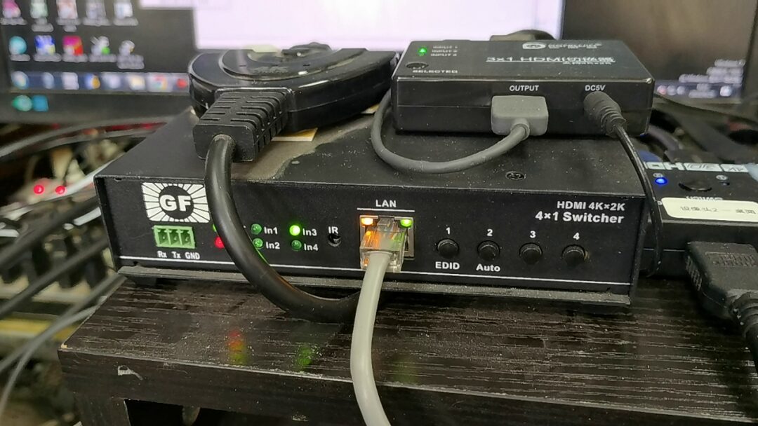
1. Control Box Communication Protocol
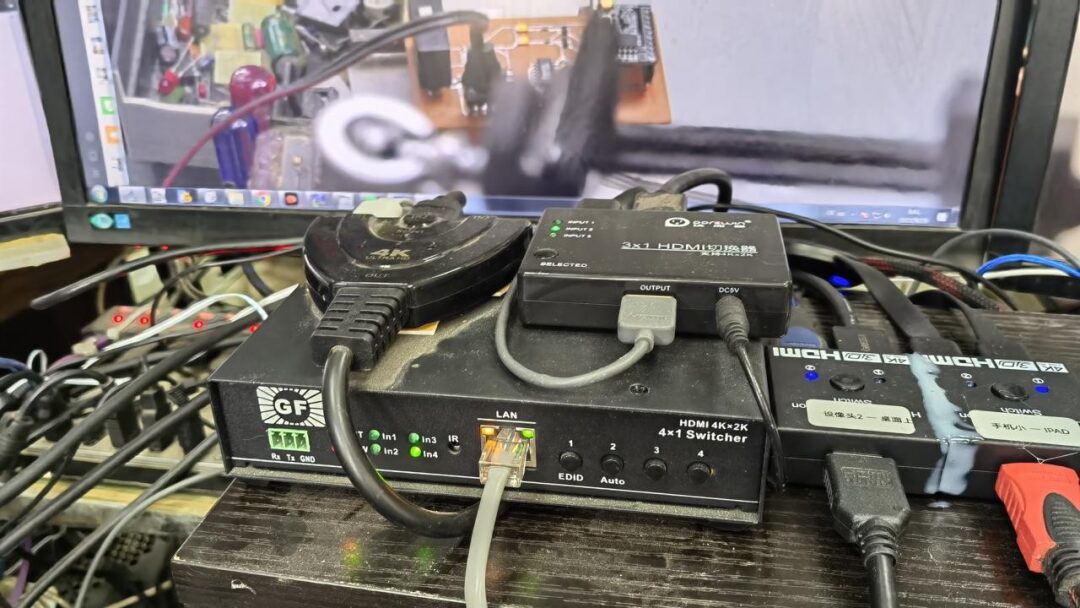
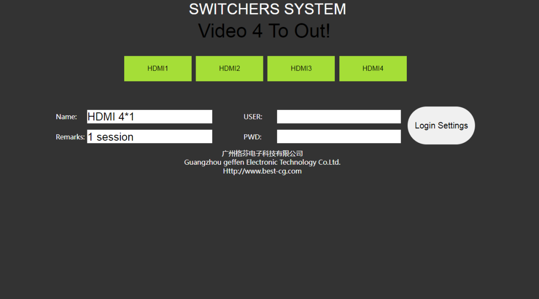
This HDMI video switch has a four-input and one-output port. It can switch between four HDMI high-definition video input signals. Its TCP control protocol is quite simple. By connecting to its default local network address and port via TCP protocol, it can replace the mechanical buttons on the control box for switching. Additionally, it can be accessed directly via a web page to control the internal controller. Clicking the buttons on the web page can also switch the video.
-
Communication IP: Default IP: 192.168.0.50 TCP Port 5050 Server Mode
-
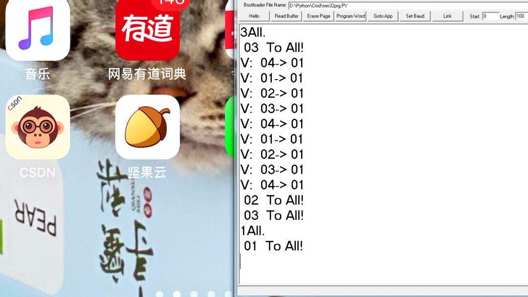
Commands: 1All, 2All, 3All, 4All.
No carriage return characters, the period (.) needs to be sent. If the IP address is modified, log in to the web interface to change it.
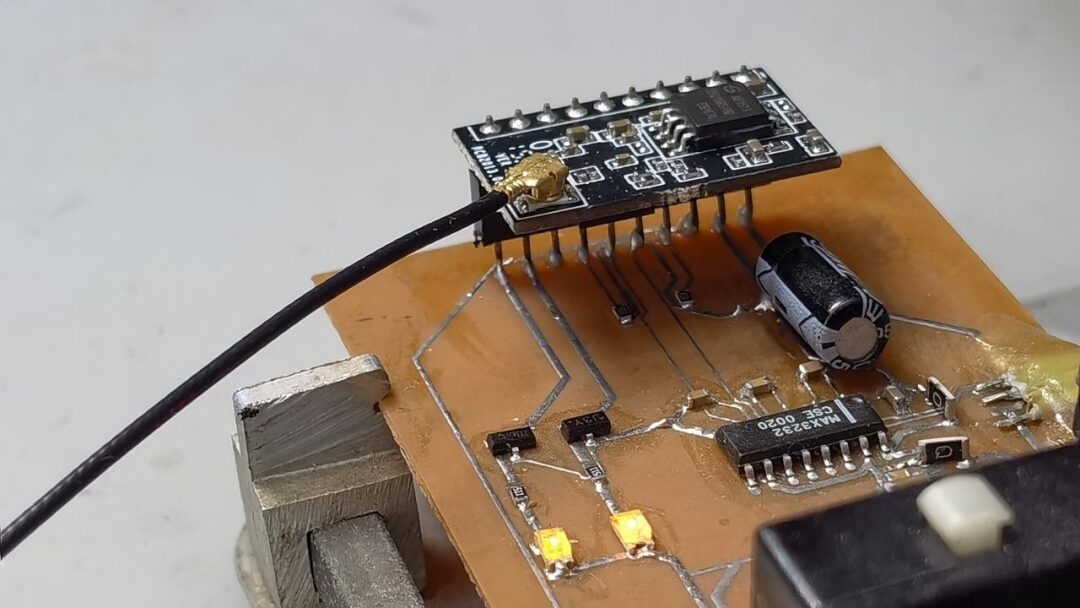
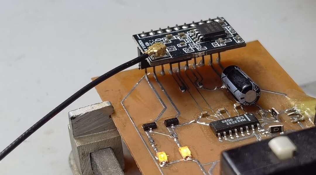
2. Configuring the WiFi Module
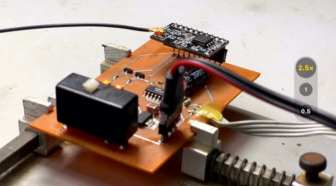
The serial to WiFi module uses a communication module. It connects the microcontroller with the networked video switch module. It has multiple working modes, and here we utilize its TCP client functionality. Its serial port is configured to 115200 for communication with the microcontroller. In the network, its SOCKET A is configured as TCP-Client. The following ports and server parameters are for connecting to the video switch controller. SOCKET B is also opened to receive UDP data sent to the serial port. After configuration, save and restart.
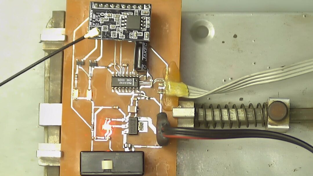
Using software, commands can be sent to the WiFi module via the serial port. It can be seen that the WiFi module successfully sends control commands to the HDMI video controller, thus verifying that the WiFi communication module is configured successfully. Next, the module will be connected to the microcontroller.
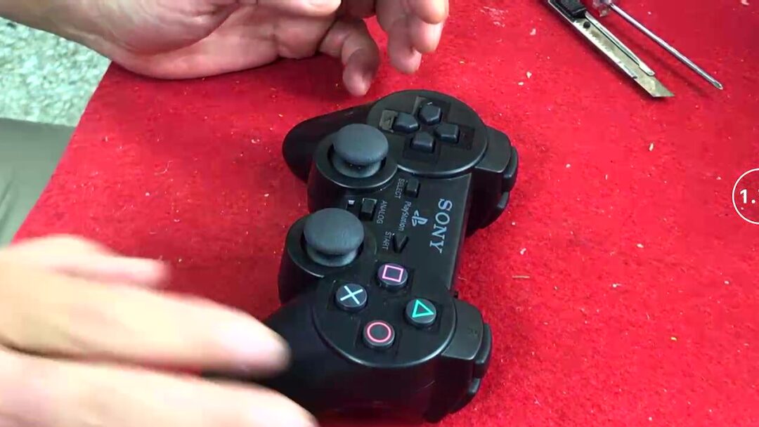
3. Mechanical Buttons
The game controller I have at hand is already damaged. I am now preparing to disassemble the buttons to use as input for the microcontroller to control video switching. Upon opening it, many switches can be seen inside. Most of these are carbon film contact switches, which cannot be used directly. Eventually, I decided to use the left and right joysticks to control video switching. They have four degrees of freedom for directional movement, allowing the switching of four video channels.
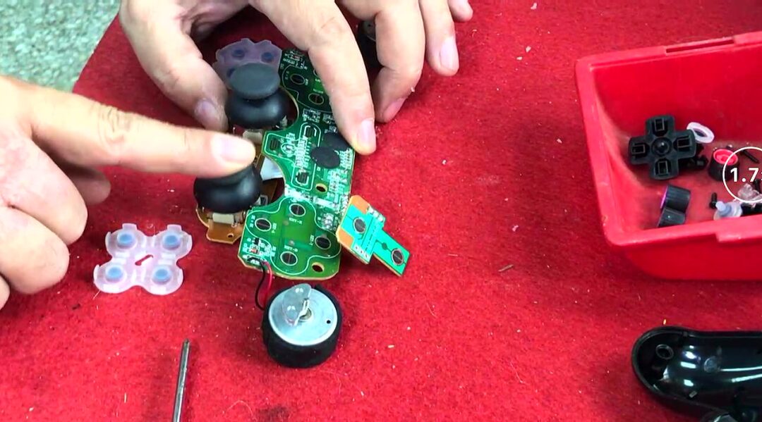
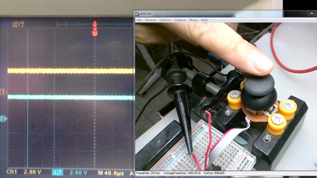
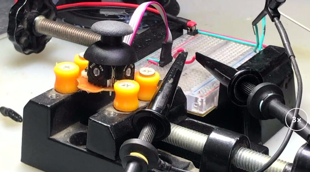
Add external leads to the two joysticks. Their two outputs are actually the midpoints of two potentiometers. By applying a +5V voltage to the potentiometers, moving the joystick will cause the two output voltages to swing between 0V and 5V. The position of the joystick can be determined through the microcontroller’s AD port.
※ Conclusion ※
This article provides a preliminary test of the scheme to control the HDMI video switcher via the WiFi module. The joystick was disassembled from a game controller. Next, the microcontroller will link the game controller and WiFi together to jointly control this video switching module.