The CAN bus (Controller Area Network), is a serial communication protocol designed specifically for industrial, automotive, and embedded systems. Its core features include multi-node shared bus, high reliability, and strong real-time performance, enabling efficient data exchange between multiple electronic devices (nodes) without the need for a central controller.
The CAN bus was developed by Bosch in 1983 to address the complex wiring issues arising from the numerous electronic control units (ECUs, such as engine control, braking systems, dashboards, etc.) in vehicles. Traditional point-to-point wiring leads to bulky harnesses, while the CAN bus connects all nodes through a single bus, significantly simplifying hardware design.
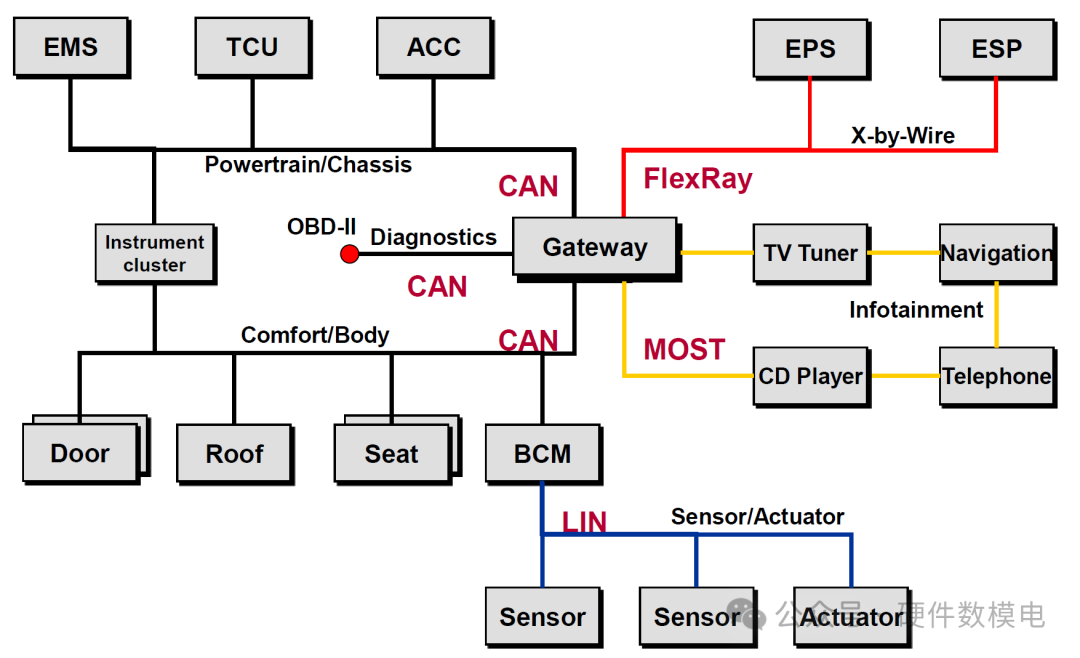
The automotive network topology is shown below, where we can see that the role of the CAN bus is to connect different components. Generally, the bus speed for chassis-related CAN nodes is 2Mbps, while the bus speed for body-related CAN nodes is 500kbps. Chassis domain nodes (such as drive systems and brake control) have very high requirements for real-time performance and reliability, often using the CAN-FD protocol to support speeds of 2Mbps and higher. Body domain nodes (such as central locking and window lifting) are non-core comfort functions, typically using the standard high-speed CAN protocol, with a speed of 500kbps.
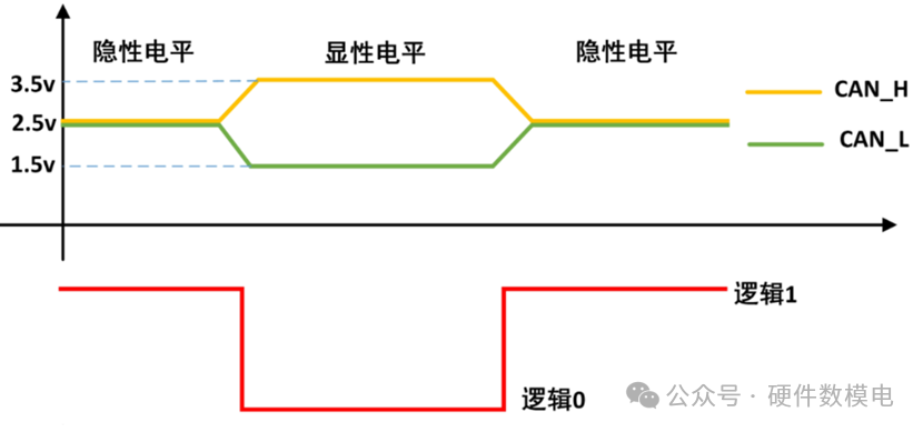
In the CAN bus, there are bothdominant andrecessive
Recessive level (logic1)
The default state of the CAN bus when idle or without data transmission
Voltage characteristicsCAN_H = CAN_L ≈2.5V
Differential voltage V_diff = CAN_H – CAN_L ≈ 0V
Dominant level (logic0)Active state when a node sends data.Voltage characteristicsCAN_H≈3.5V CAN_L ≈1.5V
Differential voltage V_diff = CAN_H – CAN_L ≈ 2V