ver0.1
Introduction
The previous article introduced the system architecture for directly injecting virtual interrupts into VMs under the GIC framework. We detailed the background of directly injecting interrupts into VMs and how to remap MSI into virtual interrupts for reinjection into vPE with the support of GIC hardware. Of course, this process also requires assistance from some supporting data structures within the GIC framework. This article will build upon the previous article to introduce the routing mechanism for directly injecting virtual interrupts into VMs, and also explain how the Doorbell mechanism introduced by GIC improves the delivery efficiency of virtual interrupts. Before reading this article, we hope everyone will review some previous articles for context:
(0)[V-00] Introduction to Virtualization – Conceptual Overview
(1)[V-02] Basics of Virtualization – CPU Architecture (Based on AArch64)
(2)[V-05] Basics of Virtualization – Exception Model (AArch64)
(3)[A-25] ARMv8/v9-GIC System Architecture (Hardware Foundations of Interrupts)
(4)[A-26] ARMv8/v9-GIC Types of Interrupts
(5)[A-27] ARMv8/v9-GIC Core Components (Basic Components of Interrupt Programming)
(6)[A-28] ARMv8/v9-GIC Interrupt Signal Routing Mechanism and Strategy
(7)[A-29] ARMv8/v9-GIC – Security Architecture Design of the Interrupt Subsystem (Security/FIQ/IRQ)
(8)[A-30] ARMv8/v9-GIC – Interrupt Handling (Interrupt State Machine/Interrupt Lifecycle)
(9)[A-31] ARMv8/v9-GIC – Interrupt Handling (Interrupt Priority/Interrupt Preemption/Interrupt Nesting)
(10)[A-32] ARMv8/v9-GIC – Architecture and Working Mechanism of LPI Type Interrupts
(11)[V-10] ARMv8/v9-CPU Virtualization – Overview of CPU Virtualization Architecture (vCPU/vPE)
(12)[V-11][A-33] ARMv8/v9-GIC – Architecture and Working Principles of Interrupt Virtualization
(13)[A-34] ARMv8/v9-GIC – Routing Mechanism of LPI Type Interrupts (Introduction to PCIE-MSI)
(14)[V-12][A-35] ARMv8/v9-GIC – System Architecture for Direct Injection of Virtual Interrupts (Direct Injection)
Main Content
1.1 Working Process of Virtual Interrupt Injection into VM
Let’s take a look at the working process of virtual interrupt injection into a VM, as shown in Figure 1-1:
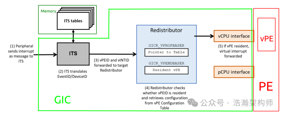
Figure 1-1 Overview of the Direct Injection Mechanism
Here is a description of this process from the manual:
• The peripheral sends an MSI to the ITS
• The ITS translates the EventID/DeviceID in the MSI. The returned mapping indicates that the interrupt is mapped to a vPE, rather than a physical LPI.
• The ITS forwards the interrupt to the target Redistributor, sending the vINTID and vPEID of the interrupt.
• The Redistributor retrieves the configuration for the vPE and vINTID from the vPE Configuration Table. It also checks whether the vPE is scheduled, using GICR_VPENDBASER.
• If the vPE is scheduled, the interrupt is forwarded to the Virtual CPU interface. Otherwise, the interrupt is recorded as pending and will be delivered the next time the vPE is scheduled.
The above process can be roughly divided into two stages: the first stage routes the input MSI to a Redistributor via the ITS; the second stage involves the Redistributor checking the current state of the vPE and delivering the current virtual interrupt to the vPE through the GIC-vCPU-Interface.
1.2 Routing Process of Virtual Interrupt Injection into VM
Regarding the delivery process of MSI type interrupts under the ARM architecture, we previously wrote a dedicated article on this topic (Routing Mechanism of LPI Type Interrupts). Here we will provide a brief introduction, as shown in Figure 1-2.
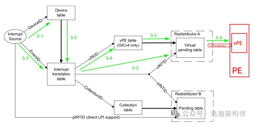
Figure 1-2 Routing Process of Direct Injection of Virtual Interrupts
Combining the above figure, we will introduce the routing process of virtual interrupts within the GIC:
(1) S-1 The ITS resolves the DeviceID of the interrupt source via the bus and traverses the Device Table entries (DTEs) using the DeviceID. The DTE stores the DeviceID and the base address of the Interrupt Translation Table (ITT).
(2) S-2, S-3 After the S-1 process, the ITS finds the ITT corresponding to the current interrupt source DeviceID, and then traverses the ITT using the EventID input from the interrupt source (passed through GITS_TRANSLATER). Here we will look at the description in the manual, which is a critical node that directly determines the next step of the interrupt signal.
An Interrupt Translation Table (ITT) is specific to each device that can create numbered events. Each entry in an ITT is referred to as an Interrupt Translation Entry (ITE).
In GICv3, ITEs are only defined for physical interrupts.
In GICv4, ITEs are defined for physical interrupts and for virtual interrupts, providing a distinction between:
• An entry for a physical LPI and the use of an ICT for routing information.
• An entry for a virtual LPI and the use of a vPE table.
ITS accesses to an ITT use the same Shareability and Cacheability attributes that are specified for the Device table.
For physical interrupts, each ITE describes the mapping between the input EventID and:
• The output physical INTID (pINTID) that is sent to the target PE.
• The ICID that identifies an entry in the Collection table, which determines the target PE for the LPI. For more information about the Collection table, see The Collection table on page 5-98.
For virtual interrupts, each ITE describes the mapping of the EventID as outlined in the preceding list, and:
• The output virtual INTID (vINTID) that is sent to the target vPE.
• The virtual PE number (vPEID) that identifies an entry in the vPE table to determine the current host Redistributor. For more information about the vPE table, see The vPE table on page 5-98.
• A physical LPI that is sent to a physical PE if a virtual interrupt is translated when the target vPE is not currently scheduled on a physical PE.
The EventID provides the index value for the table.
Next, let’s take a look at the internal structure of an ITT Entry, as shown in Figure 1-3:
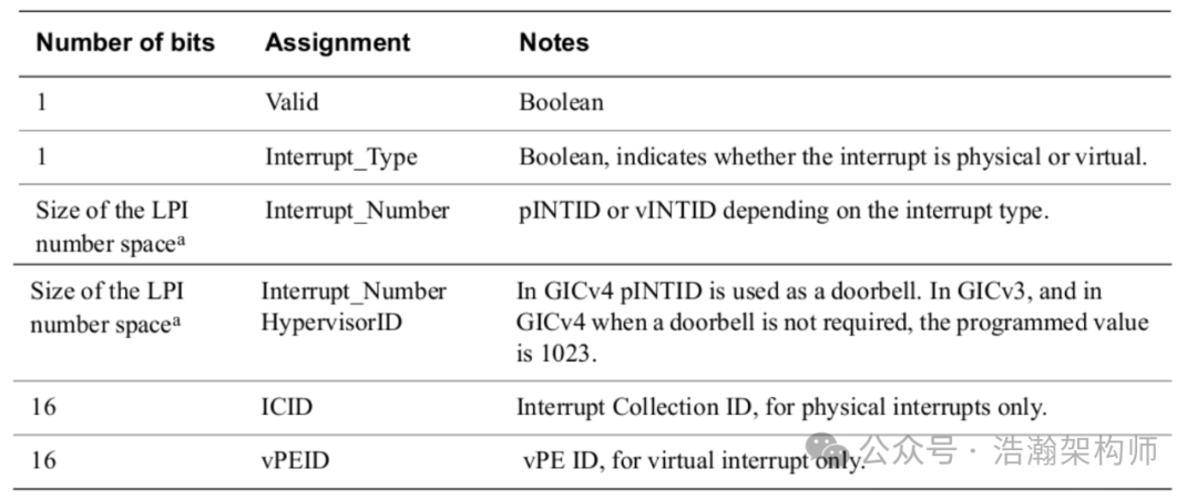
Figure 1-3 ITE Entries
Based on the above figure and the description in the manual, we summarize as follows:
• The ITT is a special node; for MSI type interrupts, it can be used by the ITS to route both physical and virtual interrupts. The Entry of the ITT has a flag “Interrupt_Type” that can be used for differentiation.
• The interrupt source (DeviceID, EventID) is mapped here to (physical interrupt: pINTID, ICID) or (virtual interrupt: vINTID, vPEID). In line with the theme of this article, we hope the mapping result by the ITS is (virtual interrupt: vINTID, vPEID).
(3) S-4 At this step, the ITS has obtained the vPEID and vINTID, and the next step is to confirm which vPE this vINTID virtual interrupt will be routed to, which is essentially determining which Redistributor the vPE (vPEID) is currently running on, and then continuing to distribute this interrupt signal. The GIC architecture relies on a data structure called the vPE Table, and we will look at the description in the manual:
vPE Table
The vPE table consists of vPE table entries that provide a mapping from the vPEID generated by the ITS to:
• The target Redistributor, in the format defined by GITS_TYPER.PTA.
• The base address of the virtual LPI Pending table associated with the target vPE.
For virtual interrupts, the Interrupt Translation Tables (ITTs) record which vPE an interrupt targets and the virtual INTID. The ITS also needs to record which group of Redistributors a vPE is mapped to. There are two ways an ITS can do this, GITS_TYPER.SVEPT indicates which model is supported:
• SVEPT=0
The ITS uses a private table to record the vPE mappings. Software must allocate memory for this table and set GITS_BASER2 to point at the allocated memory.
• SVEPT=1
The ITS re-uses the Redistributors’ vPE Configuration Table. Software must set GITS_BASER2 to point at the vPE Configuration Table allocated for the Redistributors.
We can summarize briefly:
• Depending on the configuration of the ITS, it can choose to use its own private vPE Table or the Redistributor’s shared vPE Configuration Table (as discussed in the system architecture for direct injection of virtual interrupts into VMs).
• The most important role of the vPE is to help the ITS find the mapped interrupt source (vPEID, vINTID) corresponding to the Redistributor.
(4) S-5 After the Redistributor receives the virtual interrupt signal, it checks the configuration items such as interrupt permissions in the vLPI Config Table associated with the vPE Configuration Table entry linked to the GICR_VRPOPBASER register and the scheduling status of the vPE (vPEID). Only after passing the checks can the final delivery proceed. Here we will briefly introduce the Redistributor’s check on the vPE scheduling status. The GICR_VPENDBASER register is used to indicate the current scheduling status of the vPE (note that there is a compatibility issue; the implementation of this register differs between GIC4.0 and GIC4.1), as shown in Figure 1-4.
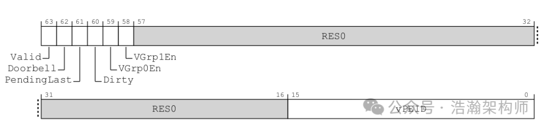
Figure 1-4 GICR_VPENDBASERFEAT (GICv4p1)
As described in the manual:
Valid, bit [63]
This bit controls whether a vPE is scheduled:
• 0b0 The virtual LPI Pending table is not valid. No vPE is scheduled.
• 0b1 The virtual LPI Pending table is valid. A vPE is scheduled.
Scheduled vPE, A virtual PE that is currently running on a physical PE. In GICv4, the scheduled vPE is specified by GICR_VPENDBASER.
(5) S-6 If the current interrupt source (vPEID, vINTID) corresponds to a vPE that is currently running on the PE-Core connected to the current Redistributor, then this virtual interrupt will be directly injected into the vPE thread through the GIC-vCPU-Interface without needing to go through the Hypervisor’s processing.
1.3 Doorbell Mechanism
1.3.1 Background
Before explaining the Doorbell mechanism, let’s briefly review what a vPE is (this was specifically introduced in our previous article on CPU virtualization), as shown in Figure 1-5.
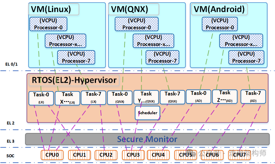
Figure 1-5 CPU Virtualization Architecture
vCPU (vPE) is the carrier and handle through which the Hypervisor allocates physical CPU resources to VMs, and this carrier is generally a thread from the operating system perspective. Since it is a thread, it involves scheduling issues, and scheduling naturally involves the state of the vPE threads, which must be managed through the Hypervisor:
Hypervisors typically divide vPEs into three categories:
Running
The vPE is currently scheduled by the hypervisor to a physical PE. For the GIC, this means the vPE can receive directly injected virtual interrupts.
Runnable (or, to-be-scheduled)
The vPE is not scheduled on any physical PE. The hypervisor knows that there is work for the vPE to do, so it will schedule it at some point in the future. Virtual interrupts cannot currently be delivered to this vPE by the GIC.
Idle
The vPE is not currently scheduled on any physical PE. The hypervisor believes there is no work for the vPE to do, and therefore will not schedule it in the future.
Regarding the state of the vPE, the description in the manual is already very clear, and we will not elaborate further. Here we will focus on a question related to the theme of this article: when a virtual interrupt arrives, its destination must be a vPE. At this point, there are two scenarios to consider: the first scenario is when the vPE thread is currently being scheduled on a PE-Core, as shown in Figure 1-6:
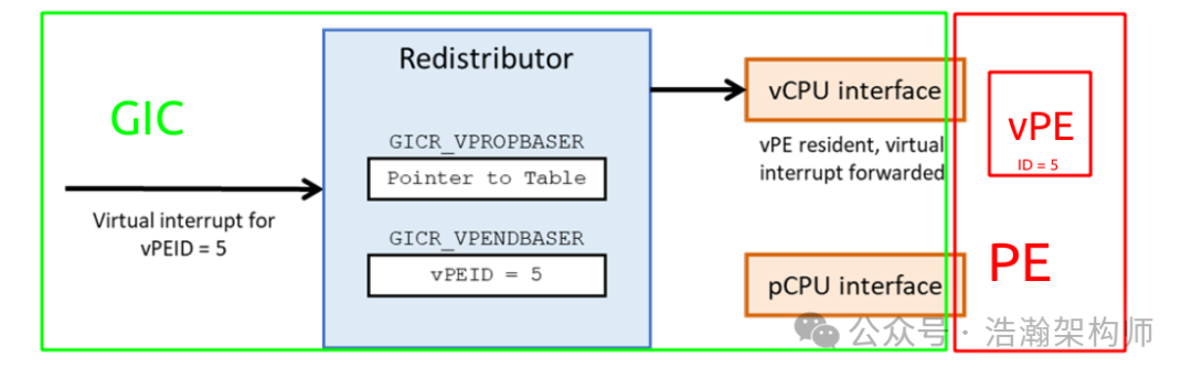
Figure 1-6 vPE (Running State)
As shown in the figure, at this time, the GIC-Redistributor does not need to hesitate and can directly deliver through the GIC-vCPU-Interface. The vPE will interrupt its current context and jump to the corresponding interrupt vector to begin execution. However, what if the current PE is not executing vPE (ID=5)? Generally, it is not a problem to wait; when the vPE is rescheduled, it will check if there are any pending virtual interrupts. If there are, it will prioritize responding to the virtual interrupts. This seems like a good choice, but what if it is a high-priority virtual interrupt? Or what if the Hypervisor’s scheduling algorithm is poor? For interrupt response, the current four-tier strategy is not friendly enough. To address this situation, ARM introduced the Doorbell mechanism to help improve the delivery efficiency of virtual interrupts:
This doorbell is a physical interrupt and would typically be taken to EL2 and handled by the hypervisor. It signals to the hypervisor that there is a pending interrupt for the non-scheduled vPE, meaning that it should be moved to the Runnable queue for future scheduling.
GICv4.1 supports two types of Doorbell:
• Default Doorbells
• Individual Doorbells (optional support in GICv4.1)
Doorbell interrupts are physical LPIs that indicate to the hypervisor that an interrupt is available for that vPE.
Each vPE can be programmed with a unique doorbell using the ITS VMAPP or VMOVP command.
When the first vLPI or vSGI becomes pending for a vPE, the GIC generates a single doorbell interrupt for that vPE. The doorbell interrupt is then masked until the vPE becomes resident.
The GIC-700 has the following doorbell characteristics:
• Doorbell IDs must be unique and not mapped to any DeviceID and EventID on any ITS.
• GIC-700 does not support individual doorbells, so GITS_TYPER.nID == 1.
• Doorbells only generate if the relevant virtual group enable is set when the vPE was last made resident. The vPE has not been made resident since being mapped.
• The GIC ignores and reports VMAPP and VMOVP commands that specify a doorbell ID that is outside of the range of GICR_PROPBASER.IDbits.
We can summarize the description in the manual as follows:
(1) The Doorbell mechanism is also a type of interrupt; for example, this Doorbell is implemented as an LPI type interrupt on the GIC-700, but this interrupt comes from the internal controller of the GIC SOC rather than an external device.
(2) The destination of the Doorbell interrupt is the Hypervisor, meaning that all Doorbell interrupts will be routed to the EL2 layer and responded to by the interrupt vector specified by the Hypervisor.
(3) The purpose of the Hypervisor’s response is to quickly reschedule the vPE corresponding to the virtual interrupt (vINTID, vPEID) to the physical CPU to obtain a time slice for execution, thereby quickly responding to the pending virtual interrupt.
(4) The allocation of Doorbell interrupts also relies on ITS commands (as introduced in the previous article) and the mapping of virtual interrupts.
(5) Doorbell interrupts are divided into two types: Default Doorbells and Individual Doorbells.
1.3.2 Working Process
Let’s outline the working process of the Doorbell mechanism:
(1) Initialization Phase: Map a Doorbell to a vPEID using the ITS command VMAPP, formatted as follows:
VMAPP (vPEID), (RDADDR), (VPT size), (VPT address), (VCT address), (doorbell)
Example:
VMAPP 6, 7, 14, (Pending Table Addr), (Config Table Addr), 8192
The above example binds the physical interrupt number 8192 to vPEID=6.
(2) Working Phase: Wake up the IDLE state of the vPE thread, as shown in Figure 1-7:
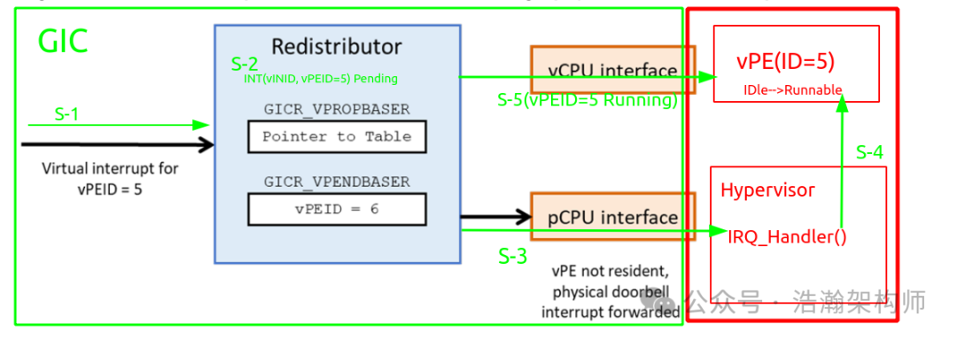
Figure 1-7 Doorbell Working Process
Taking Default Doorbell as an example, we analyze the Doorbell working process in conjunction with the above figure:
(1) S-1 A virtual interrupt (vINTID, vPEID) is mapped and forwarded to a GIC-Redistributor via the ITS.
(2) S-2 The GIC-Redistributor checks and finds that the internal register GICR_VPENDBASERFEAT’s field vPEID is not equal to 5, indicating that the current virtual interrupt (vINTID, vPEID) cannot be delivered. Therefore, it sets the virtual interrupt (vINTID, vPEID) to pending status, waiting for vPE (ID=5) to be rescheduled by the system.
(3) S-3 After checking the system status, the GIC-Redistributor will deliver the Doorbell to the Hypervisor’s IRQ_Handler. As described in the manual:
A default doorbell interrupt is generated when all of the following conditions are met:
• A virtual interrupt, which is individually enabled, becomes pending, or a virtual interrupt becomes enabled while pending.
• The vPE is not scheduled.
• When that vPE was last made non-scheduled, GICR_VPENDBASER.doorbell was written as 0b1.
• A default doorbell was supplied by the ITS mapping for the vPEID.
• The default doorbell for this vPE has not been acknowledged since the vPE was last made non-resident.
In summary, a physical interrupt of a Default doorbell is generated when the system detects that there is a pending virtual interrupt on the vPE thread and that this vPE thread is in an Idle state, then it will be delivered by the GIC-Redistributor through the GIC-CPU-Interface (this is a brief introduction; for detailed triggering rules, please refer to the manual).
(4) S-4 At this point, the doorbell interrupt signal has been responded to by the Hypervisor, and what the Hypervisor needs to do is to quickly transition the vPE’s state from Idle to Runnable, which involves specific implementations, such as adding the vPE to the Hypervisor’s Runnable queue.
(5) When vPE (ID=5) is rescheduled, the previously pending virtual interrupt (vINTID, vPEID) will be acquired by the vPE and executed at the corresponding virtual interrupt vector’s VM_IRQ_Handler().
Here we have completed the entire working process of the Doorbell. It is evident that compared to letting the GIC-Redistributor wait aimlessly, using the Doorbell interrupt can significantly improve the delivery efficiency of virtual interrupts.
1.3.3 Types of Doorbells
In the previous sections, we introduced that the Doorbell is also a type of physical interrupt, divided into two types: Default Doorbell and Individual Doorbells.
Default Doorbell
Each vPE can be assigned a default doorbell. A default doorbell is generated when any interrupt targeting that vPE becomes pending and the vPE is not scheduled.
GICv4.1 provides a new default doorbell per vPEID, specified as part of the VMAPP command.
When an EventID or a DeviceID is mapped to a virtual interrupt, a doorbell INTID can be specified in the VMAPI or VMAPTI command. If no doorbell is specified, the default doorbell for the vPE is used, if one was specified.
According to the description in the manual, the most significant feature of the Default Doorbell is that each vPE has only one type of Doorbell interrupt. A vPE can be configured to respond to multiple types of virtual interrupts, and when these virtual interrupts are pending during delivery to the vPE, only one Doorbell physical interrupt will be triggered to notify the Hypervisor for vPE scheduling. Additionally, there are some principles to follow when using Default Doorbells:
(1) The Default Doorbell is also an interrupt, so it must respect all limitations and rules of physical interrupts.
(2) During the state transition of the vPE (Idle -> Runnable), the same Default Doorbell does not need to be pending again, as it is unnecessary.
(3) The Default Doorbell will only be delivered when the corresponding vPE is in an Idle state; otherwise, there is no need to deliver it.
(4) The Default Doorbell will only be triggered when the virtual interrupt needs to be responded to by the vPE after checks; otherwise, there is no need to deliver it.
We have temporarily listed the above points; detailed considerations will also depend on the working scenarios and configurations of the GIC, which can be reviewed in the manual.
Individual Doorbells
We will directly quote the description from the manual:
An Individual Doorbell can optionally be set per-virtual interrupt, rather than per-vPE. This means that a hypervisor could potentially take different actions depending on which interrupt targeting the vPE had become pending. For example, most interrupts could use the Default Doorbell and just cause the vPE to be marked as runnable. A high-priority interrupt could be assigned an Individual Doorbell and cause immediate re-scheduling.
Individual Doorbells do not have all the same guarantees that the Default Doorbells do. In particular:
• There is no guarantee that an Individual Doorbell will be generated.
• Software cannot register whether it wants an individual doorbell when making a vPE non-scheduled. If one has been supplied for the virtual interrupt, it will be generated while the vPE is non-scheduled.
Software can allocate the same physical INTID for multiple virtual interrupts, as long as all those interrupts belong to the same vPE.
Support for Individual Doorbells is optional, with support reported by GITS_TYPER.nID.
The main difference between Individual Doorbells and Default Doorbells is that Default Doorbells are only bound to one vPEID, while Individual Doorbells are directly bound to virtual interrupts. Currently, there is no specific implementation of Individual Doorbells found, so we will not elaborate further; readers can refer to the manual for more information.
Conclusion
This article was intended to write about the software architecture of virtual interrupt injection into VMs, but as I wrote, I found the length exceeded, so I changed the plan to provide a detailed introduction to the routing mechanism of direct injection of virtual interrupts into VMs. First, we introduced the working process of directly injecting virtual interrupts, then detailed how physical interrupt signals are mapped to virtual interrupt signals and how they are delivered to the vPE. Finally, we discussed how the Doorbell mechanism improves the delivery efficiency of virtual interrupts when the vPE is not scheduled for execution, and concluded with the types and characteristics of Doorbells. Thank you for your time, and please follow, comment, and share.