How can one know?
This article is translated from the “2017 IEEE International Conference on Vehicular Electronics and Safety (ICVES)”
Included article: Safety Assessment of Automated Vehicle Functions by Simulation-based Fault Injection
Original authors: Garazi Juez, Estibaliz Amparan
Editor’s note
When analyzing the concept phase of automotive functional safety based on the existing version of ISO 26262, theoretical methods such as FMEA (Failure Mode and Effects Analysis), FTA (Fault Tree Analysis), and DFA (Dependent Failure Analysis) are often used to analyze failure impacts and derive safety goals and requirements. However, when faced with the complex system of automated vehicles, the impact of a failure may not always be known in advance. To address this issue, under the premise of known fault types, the authors introduce fault injection (Fault Injection, FI) simulation tests as a supplement to the aforementioned safety analysis methods, improving failure impact, safety goals, and safety requirements based on experimental data.
Abstract: With the development of automated vehicles, ensuring vehicle safety in the event of a fault has become increasingly important. This paper proposes a simulation-based fault injection method (Sabotage) to supplement traditional safety analysis methods in the concept phase of ISO 26262, obtaining failure impacts based on experimental data and refining safety goals and requirements. This method is then applied to the safety analysis of the lateral control system of automated vehicles, determining the impact of faults that occur in its model, based on maximum lateral error and steering saturation, to derive the Fault Tolerant Time Interval (FTTI) and deduce safety goals and requirements.
*Steering saturation: Refers to the inability to continue turning once the steering control reaches saturation.
1. Control Architecture of Automated Vehicles
This paper focuses on the functional safety research of Highly Automated Vehicles (HAV). The HAV architecture is mainly divided into lateral and longitudinal control. This study focuses on the lateral control system, which aims to guide the vehicle along the optimal path and consists of three basic functions:
-
Behavior Planning: Selecting the best path based on vehicle behavior (such as lane keeping, lane changing, or obstacle avoidance).
-
Trajectory Control: Calculating and maintaining the vehicle on the correct trajectory through control algorithms.
-
Steering: Controlling the steering wheel to drive the vehicle along the planned path, with inputs from the trajectory control module’s calculated correction values.
2. SABOTAGE Framework Based on ISO 26262
1
Framework: SABOTAGE
The existing version of ISO 26262’s concept phase primarily conducts safety assessments through safety analysis methods such as FMEA. Due to the complexity of automated vehicle systems, the impact of a specific failure may not be known in advance, leading to incomplete analysis results. Fault injection provides an effective supplementary method for assessing the safety and controllability of advanced automated systems. Under the condition of known fault types, fault injection can yield the impact of a fault occurring during system operation and related fault data. Figure 1 illustrates the safety analysis method for automated vehicle functions based on fault injection simulation. This method can serve as a supplementary means to evaluate the safety of a certain architecture in the early design phase. By analyzing simulation data, trade-offs and selections can be made among several optimal safety concepts.
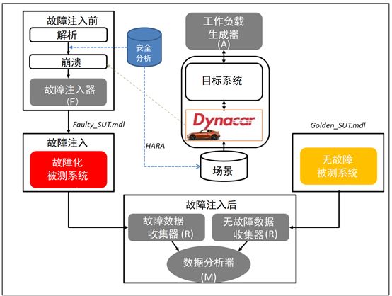
Figure 1: Sabotage: Simulation-based Fault Injection Framework
Based on this framework, the general process of the proposed Sabotage method in this study is as follows:
Step 1: Identify Failure Modes. First, the main functions and fault types of the relevant items must be known. Then, correctly identify functional failure modes to obtain data on their impacts (at the system/vehicle level). This means that if these failure modes are defined at the system level, their impacts will be reflected at the vehicle level. These faults/failure modes are associated with general fault models stored in a common fault model library (Omission, Frozen, Delay, Invert, Oscillation, Random). These general fault models are pre-set and are specific fault models for simulating any component/system functional failure mode.
Step 2: Configure Fault Injection Tests. After preliminary analysis of the system, fault injection tests must be configured as part of the workload generator, which includes setting up tests and driving scenarios, as well as generating a fault list:
-
Target: Where to inject faults?
-
Fault Model: What is the best fault model representing the functional failure mode?
-
Trigger: How to trigger faults in the system?
-
What are the observation points for fault impacts?
-
How to define the conditions under which the vehicle loses its controllability?
For each fault the user wants to inject, the fault list must clearly specify the involved fault model, target signal (fault localization), time-based or path position coordinates (X,Y) for fault trigger conditions, and fault duration. This information forms the basis for generating the fault injector (Saboteur). The fault injector is a component added to the system behavior model for fault injection. A fault is injected for each generated target signal.
The test configuration includes the selection of the vehicle and the definition of operational situations:
-
Location: Highway, City;
-
Road Conditions: Uphill, Curves;
-
Environmental Conditions: Good, Heavy Rain;
-
Traffic Conditions: Smooth;
-
Vehicle Speed;
-
Behavior: Stopping, Overtaking, Lane Keeping;
-
Potential Risk Participants: Driver, Passengers, Pedestrians;
The test scenarios are selected by the scenario configurator based on the previously defined operational situations to load the best driving scenarios into the Dynacar platform (a real-time vehicle dynamics simulation system).
Step 3: Create the Faulty System Under Test. For this, the fault injector module creates fault generator code based on the information from the fault list and common fault model templates. This process can be automated based on data from libraries and lists.
Step 4: Compare the simulation results of the faulty system with those of the fault-free system, analyze the fault impacts, and derive appropriate safety goals and safety requirements.
2
Using Sabotage in the ISO 26262 Concept Phase
The Sabotage method mentioned in the previous section can be applied in the concept phase of ISO 26262. Under the premise of known functions and fault types of relevant items, fault injection simulation can be used in the hazard analysis and risk assessment process to obtain the impact of a fault and refine safety goals, leading to the derivation of safety requirements in the functional safety concept process. The specific applications are as follows:
1. Hazard identification through fault injection rather than safety analysis methods like FMEA. The Dynacar virtual environment allows for a visual representation of hazards (e.g., when the vehicle fails to turn when it should).
2. Refining safety goals based on simulation results and hazard identification.
3. Determining FTTI and safety states. As shown in Figure 2, FTTI is the time from when a fault is injected to when a hazard occurs. For advanced automated driving systems, FTTI determines the level of fault tolerance required to prevent the vehicle from losing control (e.g., redundancy, functional degradation).
4. Comparing the simulation results of fault-free and faulty systems, safety requirements can be derived from the maximum differences between the two simulations.
5. Based on previous results, safety requirements will be categorized into the functional safety concept.
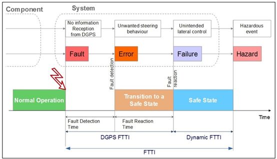 Figure 2: Fault-Error-Failure Chain and Definition of FTTI
3. Safety Assessment of the Lateral Control System
This section provides an example of applying Sabotage to the safety assessment of the existing lateral control system (part of the lane-keeping function of advanced automated vehicles) based on the ISO 26262 concept phase. Since this model lacks appropriate safety mechanisms, analyzing FI simulation results can address the following issues:
-
Obtaining impact data for specific faults at the vehicle and relevant item levels based on fault injection simulation results.
-
Completing safety analysis: determining safety goals (including FTTI values and safety states), functional safety requirements, and safety concepts.
The following is the analysis process and results of this study in the ISO 26262 concept phase:
1. Definition of Relevant Items
As described in Chapter 2, the application premise of the proposed method is to clarify the functions and fault types of relevant items in the ISO 26262 relevant item definition process: lateral control relevant items can be decomposed into multiple functions and sub-functions, with faults including: steering (Omission, Commission), trajectory control (Omission or Commission), behavior planner (unnecessary local planning, unnecessary perception, unnecessary decision-making).
2
Hazard Analysis and Risk Assessment
FI simulation results can serve as a supplementary method outside of safety analysis methods for this process, primarily based on simulation for hazard identification and obtaining safety goals (mainly FTTI values).
The FI simulation test conducted in this study involved a vehicle traveling at a constant speed of 45 km/h with lane-keeping functionality enabled in a smoothly flowing urban environment, triggering faults while the vehicle was navigating curves, replicating functional failure modes related to differential GPS (DGPS) and the steering system. The fault list set in the experiment is shown in Table 1.
Table 1: Example of Fault List*
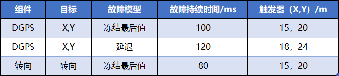
*This table is only a partial example of the fault list in this study, and does not correspond one-to-one with Table 2.
Following the steps in Chapter 2, the fault generator automatically injects faults based on the previously established fault list. To produce the most severe impact, these faults are triggered at several curve points to achieve the most significant effect. Since the primary goal of our simulation is to calculate the FTTI value for lateral control, the observed signals are lateral error and steering saturation. Figure 3 illustrates the calculation principle of FTTI for steering control.
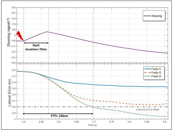
Figure 3: Calculation Principle of FTTI
The maximum lateral error defined by the following formula serves as the standard for system loss of control:
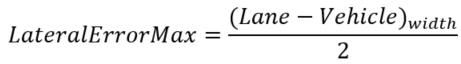
Table 2 describes the hazard identification information obtained from FI-based simulation results. By modeling failures at different relevant item levels using common fault models, the impacts at the vehicle level and the resulting hazardous behaviors can be measured.
Table 2: Impact of Failures at the Vehicle Level
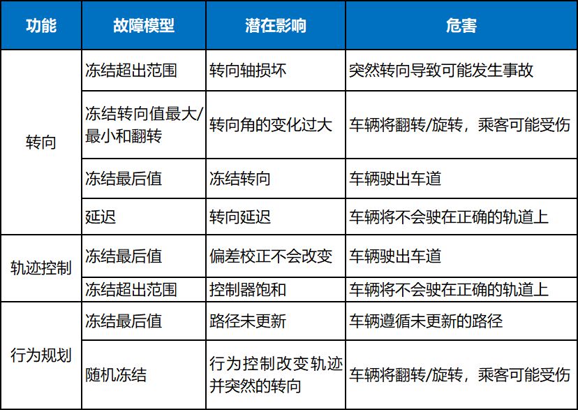
Based on Table 2 and simulation test data, partial results of hazard analysis and risk assessment can be analyzed, as shown in Table 3, which includes the FTTI values of the most severe failure modes (represented as fault models) for specific functions calculated based on Figures 2 and 3. The fault duration is the time taken to handle the fault appropriately (transition to a safe state). For example, a fault related to the trajectory controller can exist in the system for 400 ms before a hazard event occurs: 240 ms for detection and reaction, and 160 ms to control the fault, thus ensuring compliance with safety goals. The specific safety goal definitions in Table 3 are shown in Table 4.
Table 3: Hazard Analysis and Risk Assessment
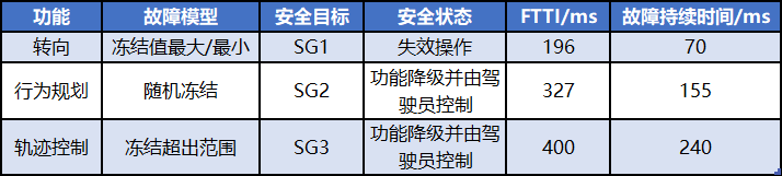
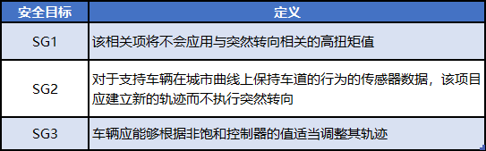
Table 4: Safety Goals
3. Functional Safety Concept
Based on the safety goals obtained from the previous process, functional safety requirements are derived in conjunction with FI simulation results, as shown in Table 5. The calculation formula for maximum lateral error is as follows:
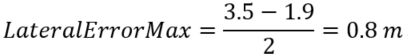
Table 5: Safety Requirements
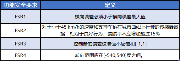
Thus, functional safety requirements are obtained through simulation data rather than traditional dependent failure analysis (DFA). The main conclusion is that the current lateral control design cannot ensure the system is disturbance-free; therefore, its architecture needs to be redesigned to ensure this property, meaning the steering system should be redundant to achieve the required availability level. Specifically, based on the data in Table 3, to prevent hazardous occurrences, faults related to the steering function must be controlled within 196 ms. If the vehicle rolls over or spins, passengers may be injured; therefore, the steering function must be available within 70 ms. Regarding failures related to behavior planning, such as failures caused by DGPS faults, the response time is 155 ms, thus appropriate functional degradation may be required. Finally, different functions must be correctly partitioned to avoid cascading failures.
4. Conclusion
This paper introduces a simulation-based fault injection method for assessing the safety of automated vehicle functions and applies this method to a case of urban vehicles with embedded automated lateral control functions. The focus of this paper is on determining the FTTI values for permanent faults based on maximum lateral error and steering saturation. A major advantage of the proposed method is that it can serve as a supplementary safety analysis method, achieving an ISO 26262 compliant safety assessment process.
Source: Tongji University Intelligent Vehicle Research Institute, Testing and Evaluation Research Laboratory
If you like it, please “favorite” or “share”; if there is any infringement or improper citation, please leave a message or contact 13636581676

Click the lower left corner“Read the original text” to learn more about the details of each conference