Skip to content
Click the blue text above to follow us
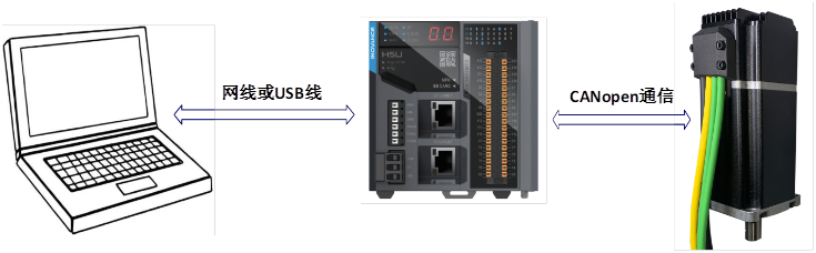
This article introduces the use of Limasen’s CANopen communication integrated low-voltage servo motor on the Huichuan H5U PLC. This part mainly explains the setup of the environment and the debugging functions provided by the software.
The main components of this system are a computer, Huichuan PLC (H5U-1614MTD-A8), and PMM series integrated servo motor (PMM6040B CANopen communication).
2. Environment Preparation
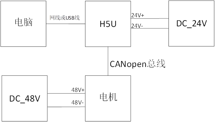
Connect all devices according to the wiring diagram below
Install the “AutoShop” software: Follow the prompts for a standard installation
Double-click to open the “AutoShop” software, the interface is as shown in the above image
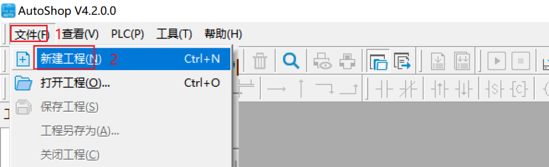
Click “File” – “New Project” in sequence, as shown in the above image
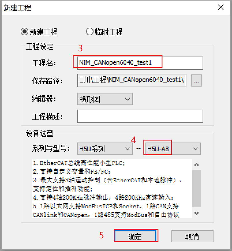
In the pop-up window, enter the project name, for example, “NIM_CANopen6040_test1”, select device “H5U-A8”, and click “OK”, as shown in the above image
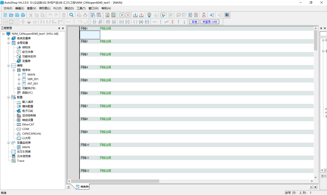
The interface of the newly created project is as shown in the above image
4. Communication Configuration and EDS File Installation
1. Communication Configuration
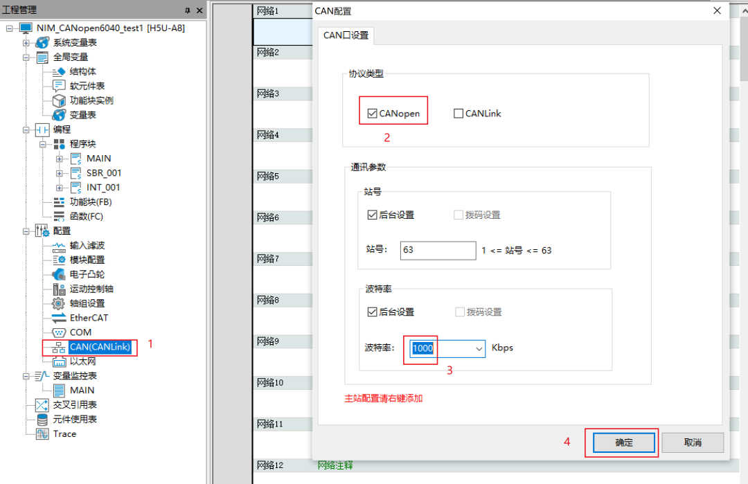
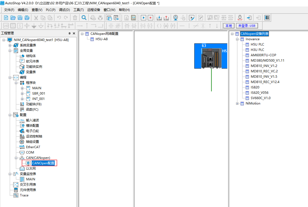
Click on the “CAN(CANLink)” under the left “Project Management Bar”, select “CANopen” in the pop-up window, set the baud rate to “1000”, and click “OK”, as shown in the above image
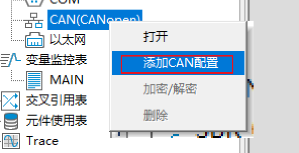
Right-click on “CAN(CANopen)”, select “Add CAN Configuration”, as shown in the above image
Double-click on “CANopen Configuration”, the “CANopen Device List” will pop up on the right, as shown in the above image
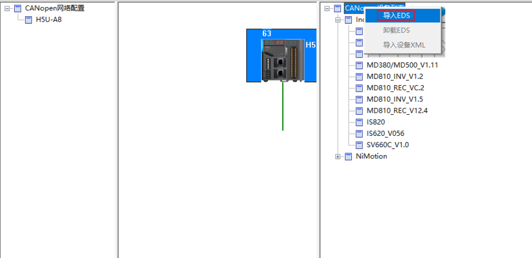
Right-click on the “CANopen Device List”, click on “Import EDS”, select the corresponding EDS file, as shown in the above image
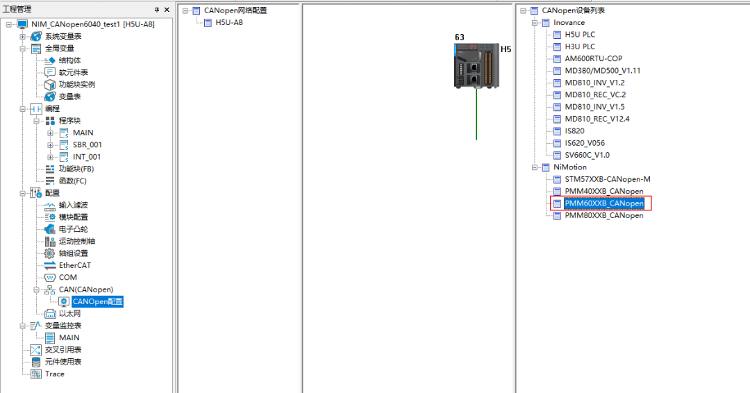
After completing the above steps, you need to restart the software. If the “PMM60XXB_CANopen” file appears in the restarted software interface, it indicates that the EDS file has been successfully installed.
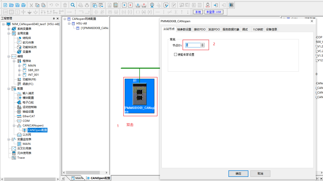
Click on the right “PMM60XXB_CANopen” file, as shown in the above image
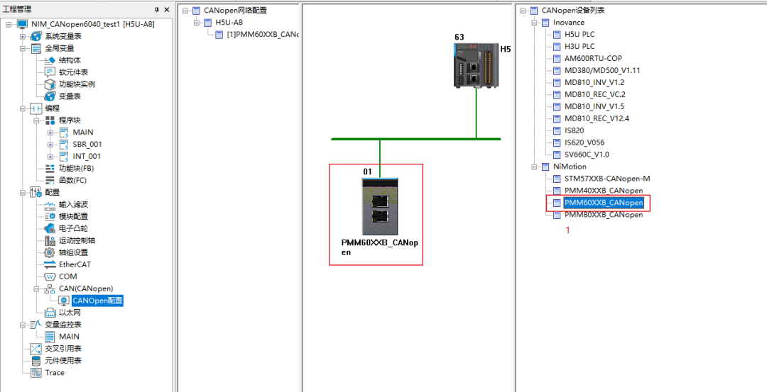
Double-click the icon that appears in the middle, and enter the node count in the pop-up window, as shown in the above image
6. PLC Communication and Program Download
1. PLC Communication Status Test
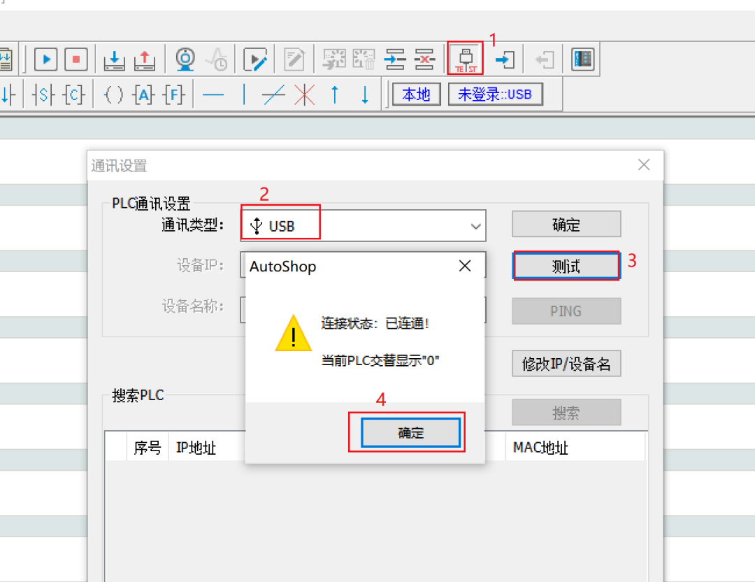
Click “TEST”, in the pop-up window select “USB”, click “Test”, as shown in the above image, indicating that the PLC is successfully connected to the computer. Click “OK” (this is an example using USB, install the USB driver as needed)
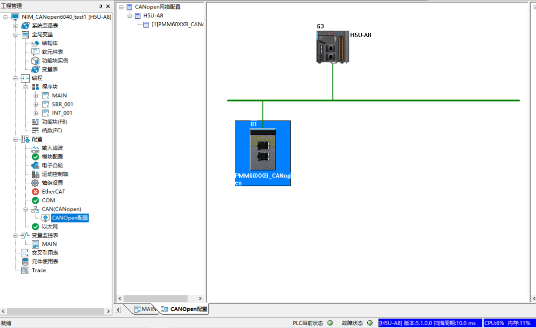
As shown in the above image, click in sequence “Compile” – “Download” – “Run” – “Monitor”
The normal status interface is as shown in the above image
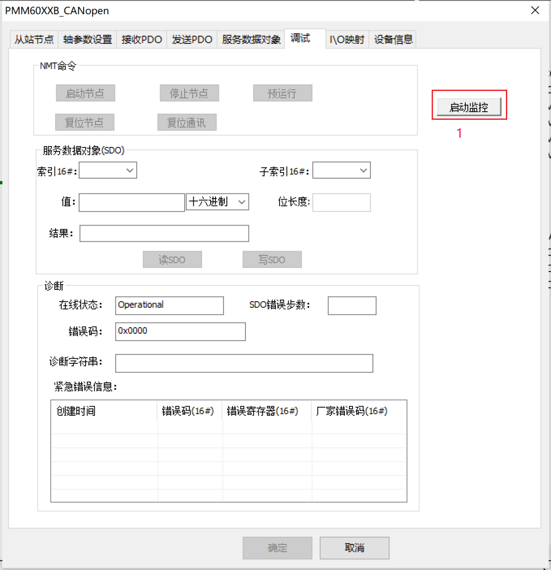
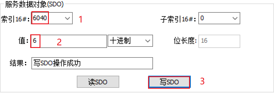
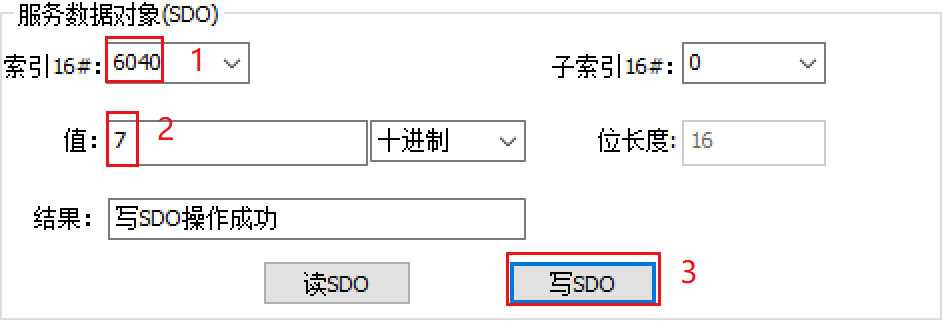
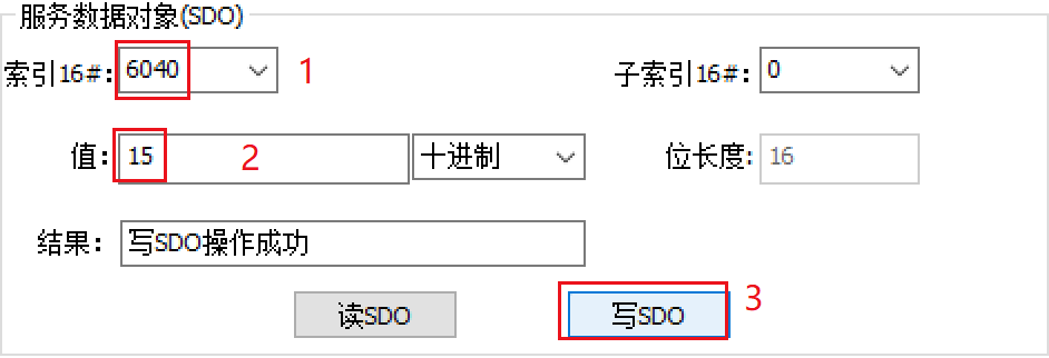
1. Enter Debugging Interface
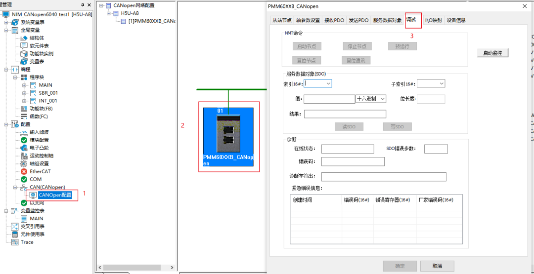
Click in sequence “CANopen Configuration” – “PMM60XXB_CANopen” – “Debug”
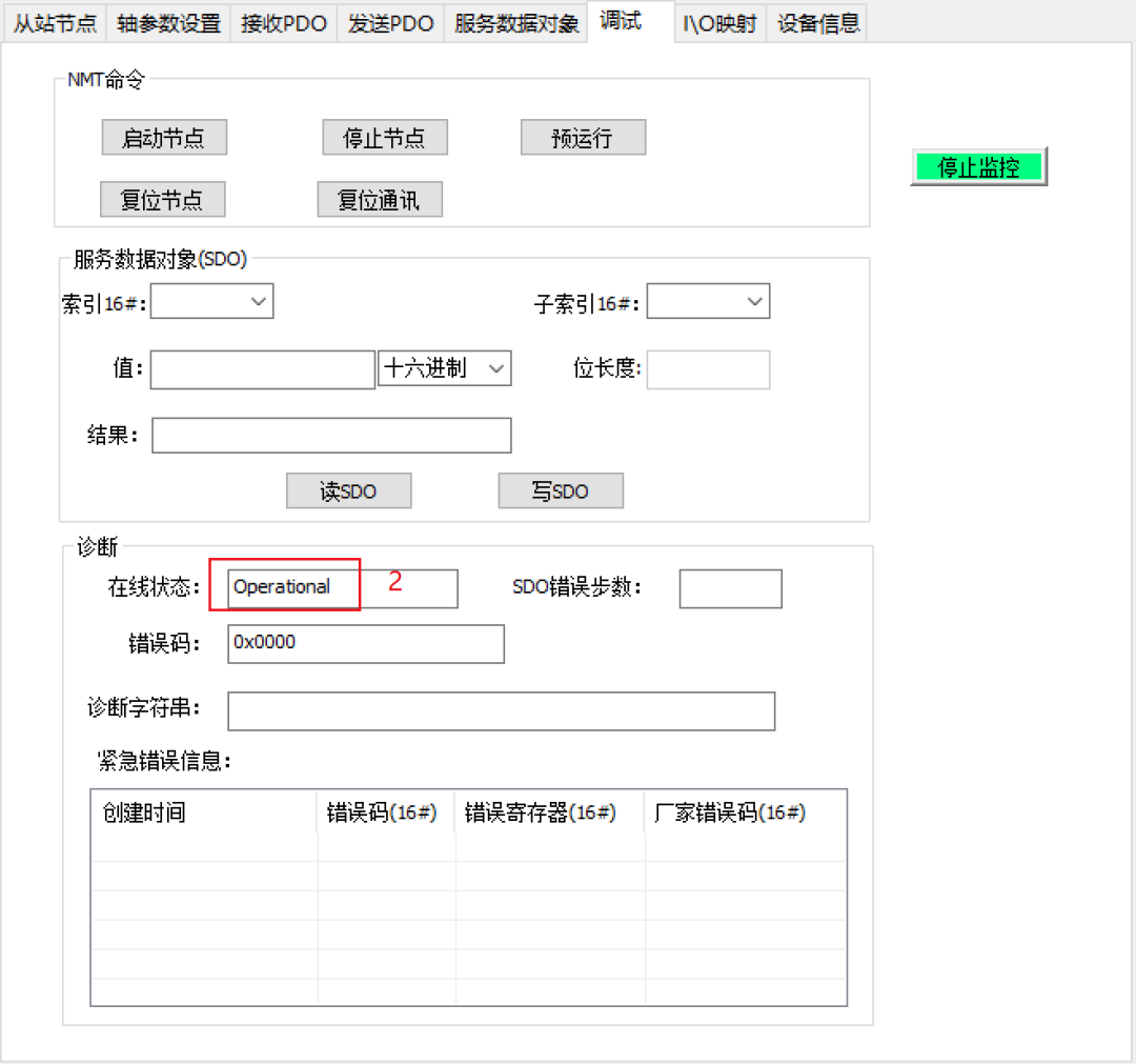
2. Click to Start Monitoring, Status as shown below
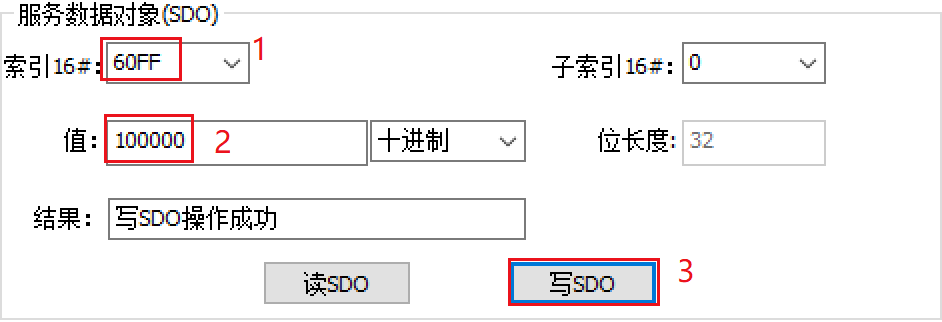
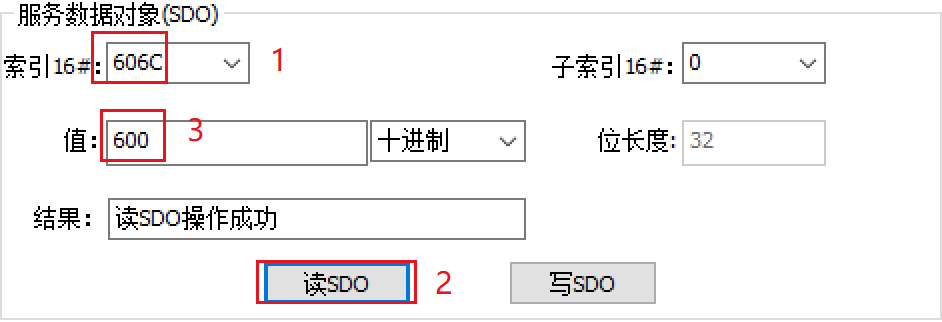
8. Read Speed, Corresponding to 600rpm
After completing the above steps, the environment setup and software debugging have basically been achieved. If you encounter any issues during the process, please contact us or leave a message.
That concludes today’s sharing. For more exciting content, please follow us! Intelligent control, driving the future!