Click the above “Power Automation Equipment” to follow with one click!

State Grid Corporation of China Science and Technology Project (100% Non-water Renewable Energy Grid Protection Adaptability Analysis and New Principle Research) (5100-202140339A-0-0-00).
(The following is the main content of this article, see the original text in “Power Automation Equipment” 2022, Vol. 42, No. 6)
Active Injection Fault Location Method for UPFC Access Lines

Zheng Tao, Wang Yunpeng, Ma Jiaxuan, Song Xiangyan
(North China Electric Power University, National Key Laboratory of New Energy Power Systems)


Scan QR Code | Read Full Text
Abstract
In response to the issue that the accuracy of traditional passive fault location methods cannot be guaranteed in the scenario of Unified Power Flow Controller (UPFC) access lines, this paper proposes an active injection fault location method based on the idea of coordinated control and protection. After isolating the fault in the access line, this method fully utilizes the high controllability of the modular multilevel converter-based UPFC, switching the series side modular multilevel converter to an additional control mode, actively injecting characteristic voltage into the access line, and then achieving fault location through a single-ended differential equation solution algorithm. The proposed method uses UPFC as a signal source to inject electrical signals into one side of the access line to construct the fault location equation, solving the problem that passive fault location methods are easily affected by UPFC operating characteristics and transition resistance, improving the accuracy and reliability of fault location. Finally, a UPFC access line model is built on the PSCAD/EMTDC simulation platform, and the simulation results verify the feasibility and effectiveness of the proposed fault location method.
1
Research Background
As a typical representative of the new generation of Flexible AC Transmission System (FACTS) devices, the Unified Power Flow Controller (UPFC) can flexibly control line flows and increase the power delivery limit; at the same time, it can provide dynamic reactive support for the AC bus, enhancing the stability of the power system. The modular multilevel converter (MMC)-based UPFC (MMC-UPFC) has gained widespread attention in academia due to its advantages such as independent control of active and reactive power and modular design, and it has been applied in high-voltage, large-capacity transmission scenarios in Jiangsu Province, China, specifically in the Nanjing West Ring Network and the southern Suzhou power grid.
When a permanent fault occurs in the AC line connected to the UPFC, how to achieve fast and accurate fault location becomes crucial for reducing the difficulty of fault inspection, shortening fault line identification time, accelerating the restoration of power supply capability to the access line, and the UPFC flow adjustment function, further providing stable operation guarantees for its connection to the power grid.
2
Overall Research Approach and Innovations
To address the issue of accuracy in traditional passive fault location methods in the scenario of UPFC access lines, as shown in Figure 1, this paper proposes an active injection fault location method based on the idea of coordinated control and protection. After isolating the fault in the access line, the method fully utilizes the high controllability of the MMC-UPFC, switching the series side MMC to an additional control mode, actively injecting characteristic voltage into the access line, and then achieving fault location through a single-ended differential equation solution algorithm. The proposed method uses UPFC as a signal source to inject electrical signals into one side of the access line to construct the fault location equation, which can solve the issues of passive fault location methods being easily affected by UPFC operating characteristics and transition resistance, thus improving the accuracy and reliability of fault location.
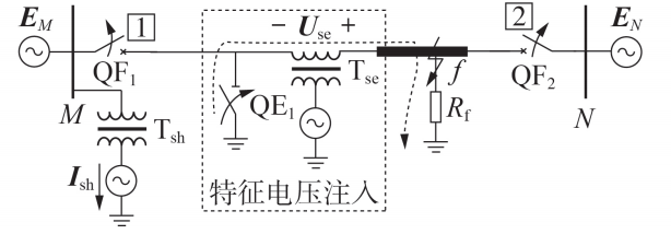
Figure 1 Schematic Diagram of Active Injection Fault Location for UPFC Access Lines
3
Principle of Characteristic Voltage Active Injection
3.1
Characteristic Voltage Injection Method
The parallel side MMC of the UPFC adopts constant DC voltage and constant reactive power control, which can continue to operate after a fault occurs in the UPFC connected line, sending reactive power to the access bus and maintaining the stability of the DC side voltage. The series and parallel side MMC can achieve power exchange, and the parallel side injects signals into the access line to enhance the energy source.
For the series side MMC, it can directly output a specified three-phase AC side voltage by changing the upper and lower bridge arm voltages. The control block diagram for active injection of characteristic voltage is shown in Figure 2, where uref_a, uref_b, and uref_c are the reference voltages for phases a, b, and c, respectively; uref_jp and uref_jn are the reference voltages for the upper and lower bridge arms of phase j. The MMC adopts the nearest level modulation method, and by inputting the set characteristic voltage reference value uref_o, the number of submodules in the upper and lower bridge arms for each phase can be determined, which is then input into the bridge arm modulation and voltage balance control. Through the coupling of the transformer, the access line can actively inject three-phase AC characteristic voltage.
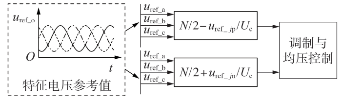
Figure 2 Control Block Diagram for Active Injection of Characteristic Voltage
3.2
Selection of Characteristic Voltage Amplitude and Frequency
The larger the characteristic voltage amplitude, the more favorable it is for obtaining the characteristic signal; at the same time, consideration should be given to the potential overcurrent lockout of the converter when injecting a larger voltage in extreme short-circuit fault scenarios. Therefore, the selection of characteristic voltage amplitude should consider both the requirements of fault location and the current capacity limits of the power electronics devices. This paper chooses approximately 2% of the rated voltage of the access line as the injected characteristic voltage amplitude.
The selection of the characteristic voltage frequency should consider hardware requirements, interference from external integer harmonics, and the influence of line parameters. This paper selects the injection voltage frequency to be 50Hz.
4
Active Injection Fault Location Method
4.1
Fault Phase Selection
After the UPFC access line actively injects characteristic voltage, the first step is to select the fault phase, and then use the corresponding fault location equation to calculate the fault distance. Figure 3 shows the schematic diagram of the active injection fault loop for different types of short-circuit fault scenarios in the UPFC access line, where the fault phase line can be selected by determining whether the access line generates characteristic current.

Figure 3 Schematic Diagram of Active Injection Fault Loop
4.2
Fault Location Equation
Taking single-phase grounding faults and phase-to-phase short-circuit faults as examples, the fault location equations for different fault types are introduced.
The schematic diagram for single-phase grounding fault location is shown in Figure 4. Assuming a ground fault occurs in phase A of the UPFC access line, after injecting the characteristic voltage, the fault phase voltage and current satisfy:
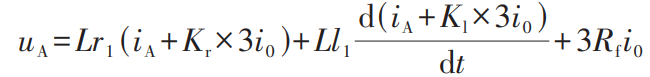
Where: uA and iA are the measured voltage and current of the fault phase A in the UPFC access line; i0 is the zero-sequence current measured in the access line; Kr and Kl are the zero-sequence current compensation coefficients for the access line resistance and inductance, where Kr=(r1–r0)/(3r1), Kl=(l1–l0)/(3l1), r1, l1, and r0, l0 are the positive-sequence and zero-sequence resistance and inductance values per unit length of the access line; L is the distance from the fault point to the UPFC line outlet.
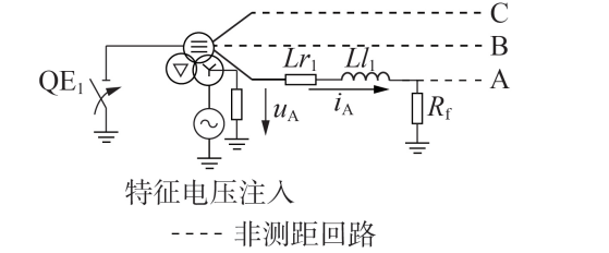
Figure 4 Schematic Diagram for Single-Phase Grounding Fault Location
The schematic diagram for phase-to-phase short-circuit fault location is shown in Figure 5. Assuming a short-circuit occurs between phases A and B of the UPFC access line, after injecting the characteristic voltage, the fault phase voltage and current satisfy:

Where: uAB and iAB are the measured line voltage and line current of phases A and B in the UPFC access line.
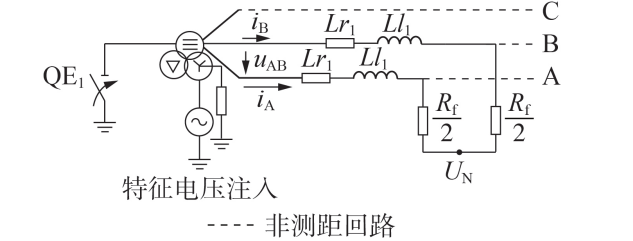
Figure 5 Schematic Diagram for Phase-to-Phase Short-Circuit Fault Location
The solvability of the time-domain linear equations is related to the frequency content of electrical quantities. Using voltage and current measurements of the same frequency can solve up to two unknowns. In the active injection fault location equations, there are only two unknowns: the fault distance L and the transition resistance Rf . Therefore, by forming a system of equations with voltage and current measurements at two different times, one can solve for the fault distance L and the transition resistance Rf .
The fault location equation algorithms for other fault types are similar to those for single-phase grounding faults and phase-to-phase short-circuit faults, and will not be elaborated here.
4.3
Process of the Active Injection Fault Location Method
The specific action sequence of the active injection fault location method suitable for UPFC access lines proposed in this paper is shown in Figure 6, which can be divided into the following three stages.
1) First stage: Fault isolation, line de-energization.
2) Second stage: After actively injecting characteristic voltage, first calculate the integral of the characteristic current for each phase, select the fault phase, and then choose the corresponding location equation to calculate the fault distance.
3) Third stage: Execute line reclosure or maintenance based on the fault location results.
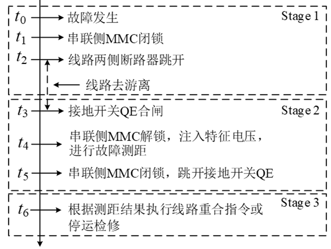
Figure 6 Action Sequence Diagram for the Active Injection Fault Location Method
5
Conclusion
This paper proposes an active injection fault location method based on UPFC for scenarios where faults occur in UPFC access lines. This method adopts the idea of coordinated control and protection, fully utilizing the high controllability of UPFC, and can actively inject characteristic voltage signals into the access line without additional equipment, thus achieving fault location using single-ended electrical measurements. This method can solve the issues faced by traditional passive fault location methods in UPFC access line scenarios, which are easily affected by UPFC operating modes and the current of the opposite power source, and has strong resistance to transition resistance and noise interference, improving the fault location accuracy and recovery speed of UPFC access lines, ensuring the safe and stable operation of UPFC connected to the power grid.
Author Information

Zheng Tao
Zheng Tao, Vice Director of the Sifang Research Institute of North China Electric Power University, Professor, PhD supervisor, with research interests in protection and control of new energy power systems. Responsible for the national-level fine course “Relay Protection of Power Systems”, and a fixed researcher in the National Key Laboratory of New Energy Power Systems.
Participated in the application and construction of the national-level fine course “Principles of Relay Protection of Power Systems” and the “New Energy Power Systems” National Key Laboratory and the “211 Phase III” project, making significant contributions.
Research Team Introduction
The Zheng Tao team from the Sifang Research Institute, School of Electrical and Electronic Engineering, North China Electric Power University, won the first prize in the China Electric Power Science and Technology Progress Award in 2016, the second and third prizes in the China Electric Power Science and Technology Progress Award in 2019, and the third prize in the Ningxia Hui Autonomous Region Science and Technology Progress Award; hosted two projects of the National Natural Science Foundation, participated in one special project of the National Key R&D Program, one 973 project, and two 863 projects; published and accepted more than 90 SCI/EI indexed papers, and authorized more than 30 national invention patents; published an academic monograph “Key Technologies and New Principles of Differential Protection for Ultra/Extra High Voltage Transformers”.
Zheng Tao, Wang Yunpeng, Ma Jiaxuan, et al. Active Injection Fault Location Method for Transmission Lines Equipped with UPFC [J]. Power Automation Equipment, 2022, 42(6): 138-145.
DOI: 10.16081/j.epae.202203018
ZHENG Tao, WANG Yunpeng, MA Jiaxuan, et al. Fault locating method based on active injection for transmission lines equipped with UPFC [J]. Electric Power Automation Equipment, 2022, 42(6): 138-145.
 Welcome to share with friends in your circle
(Media please contact us in the background)
Inheritance | Exploration | Leadership

Click “Read Original” to download the full text PDF