 For more information and inquiries, please contact “Niu Xiaoka” on WeChat: NewCarRen

Abstract
In the modern automotive and consumer electronics industries, the number and complexity of functions are continuously increasing. Additionally, there is pressure to shorten production time to market and achieve successful product designs on the first attempt, posing significant challenges for all chip designers. Effectively utilizing modeling and simulation can improve the design process to address these challenges. This paper proposes a hybrid abstract modeling strategy for top-level functional verification of chips, which significantly enhances simulation performance while achieving high accuracy in complex hardware-firmware co-verification. The digital content of the chip (composed of digital logic cores and digital functional modules) is implemented in RTL format, while the analog content of the chip is modeled using VHDL behavioral modeling with support from real signals. Therefore, top-level simulation of the chip (hardware-firmware co-simulation) can be achieved through event-based simulation techniques. Furthermore, the hybrid abstract modeling strategy and method save a significant amount of modeling work, thereby helping projects save time. To demonstrate this, the complete safety airbag system-on-chip (SoC) product has been successfully modeled using this modeling approach. In the early stages of design, this model was used for top-level functional verification of the chip while supporting optimization and debugging of hardware and firmware design activities.
1. Introduction
In recent years, the significant growth of silicon integration capabilities has made it possible to integrate entire systems onto a single chip. Such systems are referred to as system-on-chip (SoC). Generally, SoC architectures are customized for specific applications rather than being general-purpose chips. Typically, like all electronic systems, the SoC hardware architecture consists of processing elements (processors running embedded software, known as firmware, or function-specific hardware accelerators), IO devices, storage elements, and interconnect structures that link all elements together. Once the memory mapping and registers are defined and documented, firmware development can be initiated (for example, boot code that initializes the system, hardware diagnostics, device drivers, application firmware, etc.). The most fundamental characteristic of SoC is its complexity.
Typically, as shown in Figure 1, the airbag system is a heterogeneous system composed of sensors and an airbag ECU (Electronic Control Unit), where the airbag ECU consists of an airbag SoC chip set, an airbag main microcontroller (uC), and actuators. The airbag ECU serves as the hardware in multi-airbag systems as it controls the deployment of multiple airbags within the vehicle.
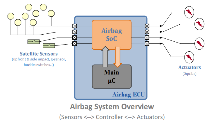
During operation, sensors installed at critical locations in the vehicle, such as buckle switches, accelerometers, or pressure sensors, continuously measure collision location, severity, and other variables. This information is provided to the airbag SoC chip set in the form of analog signals (e.g., modulated current) via sensor interfaces. The airbag SoC chip set converts the analog sensor signals into digital signals for further processing by the main uC. The converted digital sensor data is reported to the main uC via SPI (Serial Peripheral Interface) communication. Based on this information, the airbag main uC decides whether, where (location), and when to trigger the airbag (e.g., actuators). When triggered, the main uC sends a trigger command to the airbag SoC chip set, which drives the airbag ECU’s trigger interface, allowing up to 2.2A of large analog current to be supplied to different explosive resistors (depending on the impact location). These explosive resistors are heated by high current, causing a chemical reaction of the compounds surrounding the resistor, leading to the airbag deployment.
The airbag ECU in this paper employs a master-slave SPI communication system, where the main uC acts as the master/controller and the airbag SoC chip set serves as the slave/actuator. The airbag SoC also acts as a transceiver for the remote sensor network around the vehicle to the main uC. It is responsible for receiving analog sensor signals and translating and reporting sensor data to the main uC. The main uC, as the master device, is responsible for evaluating the sensor data received from the airbag SoC and requesting triggering at the correct time window and position based on the collision scenario.
2. Problem Definition: Challenges in Airbag SoC Design and Integration
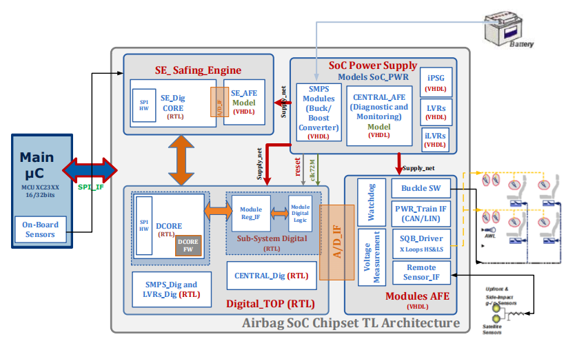
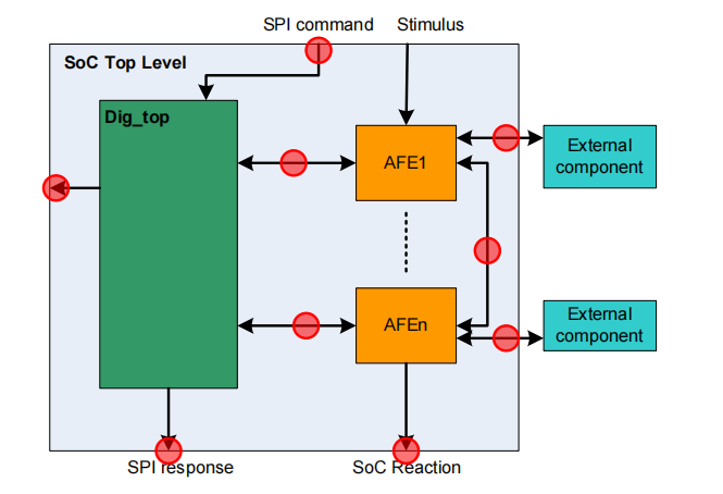
As shown in Figure 2, integrating the automotive airbag electronic system into a single SoC controlled by the main microcontroller makes the airbag SoC a very complex device. The main microcontroller (uC) serves as the master and communicates with the airbag SoC chip set via standard Serial Peripheral Interface (SPI). The main functions of the airbag SoC chip include:
· The intelligent power management unit consists of a switching power supply module—SMPS (buck and boost converters); an internal power generator—iPSG, and central power control logic that manages the power-up and power-down phases of the chip while monitoring system power integrity and logic to diagnose fault-safe states in case of integrity violations.
· The remote sensor interface supports different types of sensors, ranging from accelerometers to rotational sensors, and complies with various standards such as PSI5 (Peripheral Sensor Interface) or DSI3 (Distributed System Interface).
· The safety engine assists the main uC in observing sensor data transmission and confirming whether triggering events occur.
· The airbag activation module—detonator driver and activation logic—enables the airbag ignition current, including requirements for activation time, current, and load condition diagnostics.
These functions are distributed across hardware (analog and digital front-end (AFE)) and firmware embedded on a high-density logic digital core (referred to as DCORE – digital core). Two important concepts in hardware and firmware integration are verification and validation, which determine whether the design components meet all requirements. Since the integration of hardware and firmware is the most critical step in embedded system design, it is best completed as early as possible. However, there are many techniques for integrating hardware and firmware. The primary goal should be to avoid wasting time debugging good firmware on defective hardware or debugging good hardware running defective software.
Moreover, the automotive electronics industry has recently strongly demanded a significant reduction in time to market and an urgent need for successful designs on the first attempt. These trends pose significant challenges for design teams. It has been proven that effectively utilizing modeling and simulation is one of the key factors that can provide substantial support for designers in meeting industry requirements while addressing technical challenges. The ability to choose the correct modeling strategy and method is of great importance for such complex embedded mixed-signal chip top-level simulations, which typically involve accuracy and simulation performance (simulation speed).
3. Contributions of This Paper
This paper makes the following contributions through the proposed hybrid abstract modeling approach:
· A modeling method for hardware-firmware co-design and co-verification that supports the development of complex SoC products. Firmware, analog, and digital hardware design teams can use a common model to test the software/hardware currently in development. This also improves collaboration between multidisciplinary design teams.
· A hardware fault injection modeling and simulation method for chip functional verification using a global signal concept is proposed. This helps firmware and hardware designers verify the concepts of fault detection and permanent fault protection in the system.
· The provided hybrid abstract method also aims to bridge the gap between the “speed” and “accuracy” issues of complete chip top-level functional simulation of complex ICs. This is achievable because the models created through the modeling method are pure VHDL (direct RTL and behavioral VHDL); thus, they possess high accuracy and very fast event-based simulation.
· The data flow and communication chain concept from sensors to the airbag SoC chip interface to the main microcontroller have been successfully validated in the early stages of the design process. This ensures high trust from customers in the design team.
· Using the hybrid abstract modeling method with VHDL, the modeling team can save a significant amount of modeling work, as modeling tasks are focused solely on modeling the analog content of the chip digitally. This is feasible with support from real data, thereby supporting the design team and project in meeting product time-to-market requirements.
4. Hybrid Abstract Modeling Method
A. Challenges in Chip Top-Level Functional Modeling and Verification of Airbag SoC Chip Set:
As mentioned above, to achieve the full functionality of the airbag SoC chip set, correct interaction between digital and analog hardware is required, as well as proper interaction between firmware components. One of the challenges is that many such functional verifications can only be completed at the chip top level. Therefore, in the case of the airbag SoC product having such high complexity and integration, it is important to have an effective modeling and verification strategy that covers as many hardware and firmware functional verifications as possible without compromising accuracy and simulation speed.
Based on the practical status of other internal working groups (e.g., sensor and control groups or communication groups or IP module groups). The airbag SoC integrates several different single-chip large-scale integrations into a single chip, such as: power management chips, detonator driver chips, and embedded safety engine chips. Based on experience running complete boot simulations on the power management chip using VHDL-AMS, boot simulations take a day to resolve convergence issues. Therefore, it is not sufficient to use VHDL-AMS alone to simulate the complete airbag SoC chip set. Using the SystemC(-AMS) approach can produce very fast performance model prototypes (although it requires significant effort). On the other hand, model prototypes still need to adapt to the final hardware implementation. Compared to SystemC(-AMS) and VHDL-AMS methods, using pure VHDL hybrid abstract modeling method has many advantages because it provides:
· Accuracy: The model possesses a true RTL implementation of the complete digital logic core and its embedded firmware for more accurate and reliable results.
· Simulation Performance: Very fast event-based simulation without convergence issues.
· Workload: Complete reuse of the RTL implementation of the digital logic core significantly reduces modeling workload. Additionally, compared to the VHDL-AMS method (which requires modeling engineers to have a good skill base and experience with complex modules), the workload required to digitally model analog front-end modules in VHDL with practical value is much less. Thus, it also helps shorten the time to market for products.
The decision to use VHDL pure digital modeling methods for chip top-level simulations is driven by the following factors:
· The airbag SoC chip set deploys highly integrated very complex digital logic as well as high voltage (up to 35V) and high current (up to 2.0A) output driver circuits on a single chip.
· The architecture of the airbag SoC chip set employs digital hardware with a large number of analog hardware modules (more than 22 modules); tightly integrated with real-time interactive embedded firmware (ROM).
· The main power management unit – PMU (with switched-mode DC/DC power supply – e.g., buck, boost converters, internal power generators, and voltage regulators) performs digital control at clock rates exceeding 70MHz.
· Last but not least, due to the time-to-market requirements, fast and reliable top-level simulation setups are also needed.

B. Hybrid Abstract Modeling Method:
According to the evaluation results, the modeling strategy for the airbag SoC chip set is to establish as high-accuracy a fully digital model of the chip in VHDL as possible. This can be achieved through the following steps, as shown in Figures 2 and 4:
· The digital core logic and digital functions of the airbag SoC chip are directly reused from the RTL implementation by the digital design team.
· AFE modules (e.g., general light drivers, sensor interfaces, power management units, detonator drivers for deploying airbags, seatbelt buckle switches, etc.) are modeled based on actual data using VHDL behavioral modeling (described in Section 4.C).
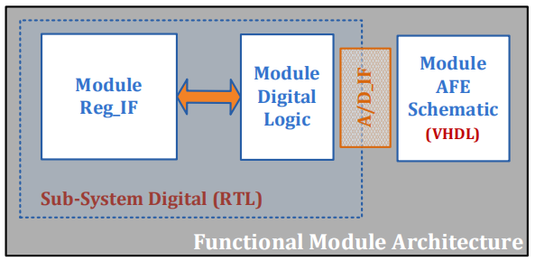
Note: Figure 3 shows the overall architecture of functional modules in the airbag SoC design. Each functional module consists of a module AFE and a subsystem digital part, where the module AFE interfaces with the external world or system load, and the subsystem digital part is controlled by the digital CORE logic of the entire SoC, divided into module logic and module register interfaces.
· A top-level netlist of the chip is automatically extracted from the final tape-out layout schematic using internally developed dedicated tools and applied to all top-level modules. This process is called “marriage,” as shown in Figure 4, and is used to replace the wiring flow when integrating the chip top-level model. The aforementioned top-level marriage process not only helps save effort in model creation but also improves the model’s accuracy regarding the final product. This is because the top-level netlist of the model and the top-level tape-out schematic are consistent.
· Finally, the firmware implementation is also directly injected into the model as a ROM mask, allowing for hardware-firmware co-simulation. In practice, the firmware team uses the hardware model to validate its firmware during development. Errors discovered during simulation are analyzed and identified as being caused by firmware or hardware, facilitating close collaboration between teams.
This method is referred to as the hybrid abstract modeling method. Implementing the airbag SoC chip set model using the hybrid abstract method allows for event-based simulation of the entire chip, significantly improving overall simulation performance.

C. VHDL Behavioral Modeling of Analog Components with Real Data Support
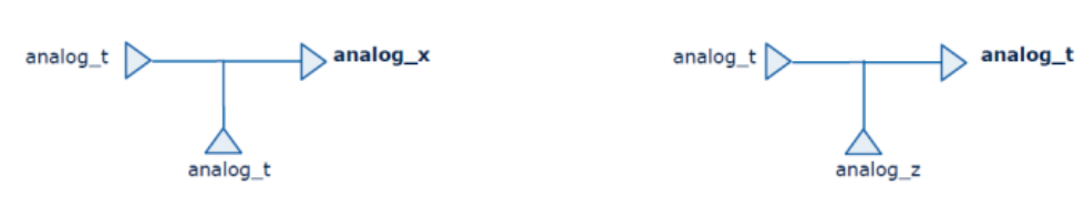
When using the hybrid abstract method, the workload of creating a complete chip model can be significantly reduced, as the workload is primarily distributed in modeling the chip AFE modules. By introducing types analog_t and current_t, analog components are modeled with a “digital” mindset, representing voltage and current symbols of the analog world, respectively. The concepts of analog_t and current_t are based on the real number type. The Analog_pack package is used to declare these two types. The Analog_pack software package was originally written to support modeling for sensor and control applications and has recently been adopted and widely used by other application groups (e.g., communications and automotive). Within the Analog_pack package, more signal types and resolution functions for simulation modeling and verification purposes can be found (as shown in Figure 5), such as:
·analog_u: unknown/undefined value
·analog_x: driver conflict
·analog_z: high impedance
The power check block illustrates how to model analog components using VHDL with real data support, which is an internal functional block of the airbag light driver AFE module, as shown in Figure 7. This block checks the power supply voltage of the airbag SoC light driver at 5v0 and 1v5 (for the analog and digital sub-blocks, respectively) to ground and returns a boolean type output Supply_ok. An output of “1” for Supply_ok indicates that the power supply voltage signals 5v0 and 1v5 remain stable, while “0” indicates that the power supply signals are unstable or out of range. The behavioral VHDL code implementation of this block is shown in Figure 6.
The supply_check core process is implemented as a concurrent process. It immediately checks the input voltage and ground levels. If the difference between the voltages remains within predefined thresholds, it returns a boolean value indicating the power supply status. In most cases, if the power is poor, the model will remain in “disabled” mode. Supply_1v5_ok and Supply_5v0_ok are general functions used in many different models of the entire chip, thus declared in the simulation support_lib library.

The complete light driver AFE functional model architecture is shown in Figure 7. As an overall model, this model strategically represents the functions and physical partitioning of the actual AFE module implementation. At this level, it has been required that the model pins are fully compatible with the circuit implementation to be integrated into the top-level of the final airbag SoC model.
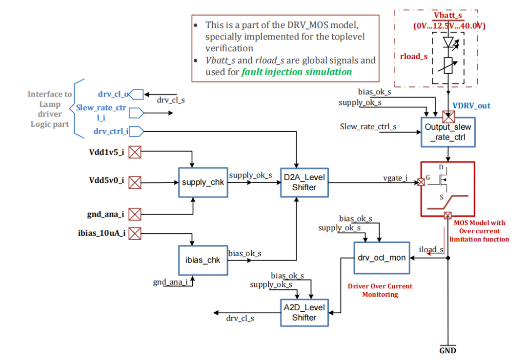
The key module of the light driver AFE is the MOS model. Its role is that of a switch with overcurrent limiting functionality. If the driver is enabled, the gate voltage will be driven to a level above Vthreshold to turn off the switch/open the transistor and allow current to flow through the LED (in this case, the light is on). This current is referred to as load current (iload_s), which is continuously monitored by the drv_ocl_mon module. In VHDL modeling, this translates to a process that remains sensitive to the iload_s current at all times. The digital logic part of the light driver module implements overcurrent detection and driver protection functions using the status reported by the driver overcurrent monitoring block. The driver on/off functionality, driver transition rate configuration, and reporting of the driver status to the main microcontroller are all accomplished through firmware using the SPI communication interface.
In general, the AFE model is validated against the circuit/schematic level by comparing the model with the actual circuit using a subset of the module-level verification suite, followed by review/approval by simulation designers, firmware designers, and functional module owners (e.g., typically responsible for digital, analog, and firmware design). Each AFE model has a specification agreed upon by simulation designers, firmware designers, and top-level verification engineers. This process helps avoid over-designing the model implementation, which often unnecessarily degrades simulation performance. Additionally, this process also helps strengthen collaboration between different discipline teams. It is of significant importance during the design phase as it allows for consensus among designers, thus reducing design errors caused by misunderstandings.
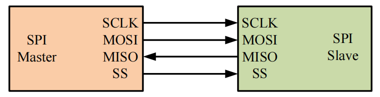
D. SPI Model for Firmware Stimulus
Instead of using the main uC model, an SPI generator model is used to generate SPI commands as a firmware stimulus source. This SPI generator is also used to check the implementation of the SPI interface hardware module. The SPI generator has four digital interfaces compliant with SPI communication standards, as shown in Figure 8, such as: sclk_o (SPI clock output), ss_o (slave select output), MOSI_o (master output slave input) command line and MISO_i (master input slave output) response line from the airbag SoC chip. The SPI frame generator can be configured to operate at different sclk_o, generating different frame lengths with different lead and lag times.
5. Fault Injection Simulation Using Global Signal Concept
The airbag SoC chip set is a safety-critical component in the airbag system. Certain parts of the airbag SoC chip set belong to the ASIL-D level of the ISO-26262 safety standard (ASIL = Automotive Safety Integrity Level). Fault injection simulation is mandatory for many safety requirements, such as fault detection and fault protection functions. As shown in Figure 7, overcurrent events caused by high battery voltage levels or low load impedance (short circuit) are considered application faults. If undetected and unprotected, such faults can damage the application drivers.
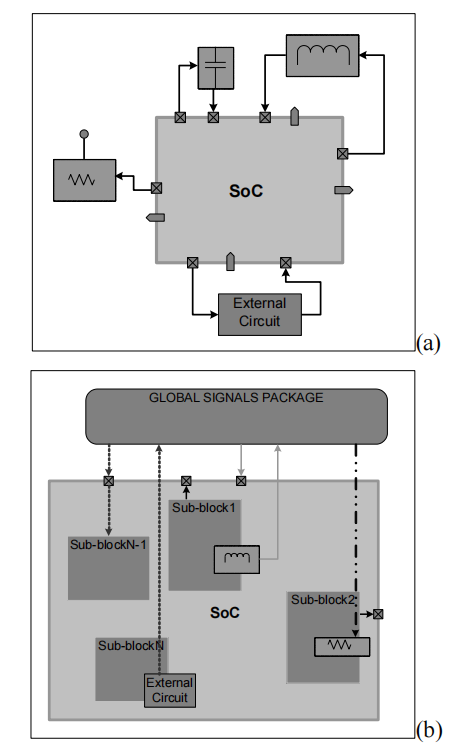
The possibility of injecting faults allows for the validation of overcurrent detection circuits and even driver protection function validation. This is also helpful for simulating different customer applications. In practice, load impedance and battery are not part of the chip, as shown in Figure 9(a) as external circuits. The fault injection concept for simulation is as follows: to inject faults during simulation, the battery voltage Vbatt_s and load impedance rload_s are modeled as analog_t type signals in the MOS model and globally declared in a separate package called the global signal package. These signals are used to calculate the iload_s current. In Figure 9(b), this is illustrated by the external application circuit modeled inside the chip model. Therefore, through the global signal package, these load signals and battery voltage can be dynamically controlled or stimulated during simulation to create different simulation events, including fault events. In other words, the global signal package must be declared at the header of the top-level test bench.
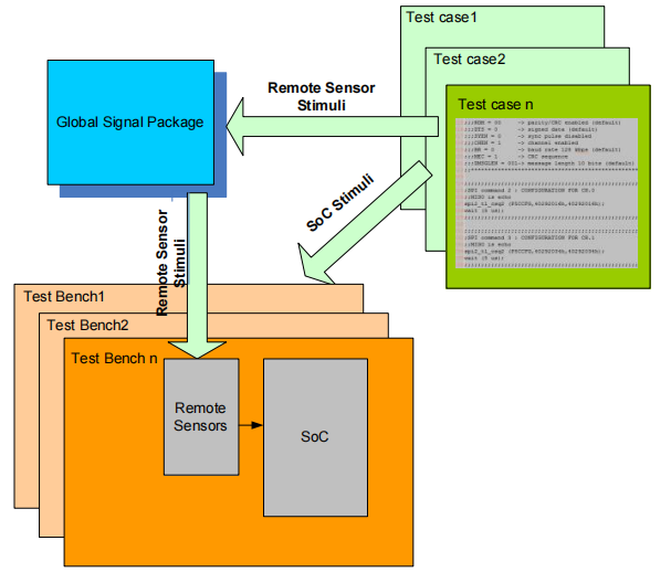
Although this concept is very simple and not labor-intensive to implement, it indeed makes fault injection and fault simulation possible and very easy. The global signal concept is also widely used to create different test scenarios for top-level verification. For example, it includes generating different sensor data patterns using the global signal concept, as shown in Figure 10. Sensor data is declared in the global signal package. Verification engineers need to define different sensor data patterns in different test case scenarios and use the global signal package to pass this data to the test bench. Validating different sensor data patterns based on various collision scenarios helps check the robustness of the airbag system, as false deployments are not allowed.
6. Model Coverage: Accuracy Assessment and Implementation Work
This section summarizes model coverage from both physical implementation and functional perspectives.
A. Accuracy Assessment of Airbag SoC Chip Set Model
Through the hybrid abstract modeling method, this model achieves high accuracy as it covers the following points of the chip’s physical implementation accordingly, as shown in Figure 11:
· Complete digital hardware architecture implementation (reuse of RTL code)
· Strict requirements for interfaces between the digital domain and the analog domain during modeling. These interfaces are verified at the top level through the sub-module model integration step of the tape-out schematic netlist. If there is a mismatch, the user receives an error message immediately during the compilation stage.
· When simulating the real top-level netlist, the top-level connections between modules are also covered. This top-level schematic is later used for chip layout.
· A ROM mask is also used for simulation. This ROM mask converts firmware implementation (C code) into a ROM structure suitable for digital processor architecture. The ROM mask is later also used for the physical implementation of the chip.
B. Model Limitations and Implementation Work
Although VHDL allows for implementing multi-field records to model voltage and current on the same pin, the authors chose the global signal sending concept to retain voltage or current information and feedback to the model. This significantly improves the implementation workload and keeps simulation behavior simple. That said, the validation of all analog modules is at the circuit/schematic level. It is part of the overall verification strategy and significantly influences the modeling method.
In practice, two modeling engineers spent approximately 3 months completing the full modeling task of the airbag SoC chip’s concept, specification, implementation, module verification, and top-level integration.
C. Confirmation and Verification Coverage of Airbag SoC Top-Level Model:
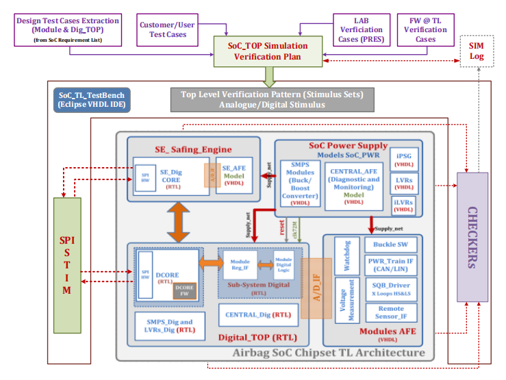
Figure 12 shows the test bench architecture used to validate the airbag SoC chip set. The test bench consists of the following parts:
· Stimulus: Digital stimuli (firmware, e.g., SPI command sequences and digital hardware) and analog stimuli (e.g., vbatt_s, rload_s, 1v5 and 5v0 power supplies, etc.). The SPI stimulus syntax contains SPI interface (SPI1 or SPI2), chip select name, MOSI command, and expected MISO response.
· Checker: The regression test suite also implements different checkers.
· SIM Log: All simulation events, including stimuli and checkers, are captured and placed into log files (text format). Users can access the simulation log files after the simulation ends.
Using the hybrid abstract model, the top-level simulation of the airbag SoC chip focuses on verifying the following aspects:
· The functions of the chip, such as power management functions, airbag activation functions, etc., require interaction between simulated/digital hardware and firmware to verify. These functions can only be verified at the chip top level. For many modules, the simulation model is highly compatible with the actual schematic implementation.
· The firmware behavior at the chip top level can also be verified; any errors found during hardware verification can be directly fed back to the firmware team for error correction, and vice versa.
· The communication chain from the main uC to the airbag SoC chip can also be verified, including sensor data transmission, command decoding, and analog hardware status reporting.
· Customer use case validation.
Electrical parameter checks are specifically targeted at functional module verification levels, employing mixed-signal verification techniques, where module implementations (RTL code and actual schematics) are used.
7. Results/Conclusion Summary
The hybrid abstract modeling strategy and method have been successfully applied to the design of complex airbag SoC chip set products. The chip has completed tape-out, and successful results have been achieved using this method. The entire airbag SoC chip set model employs pure VHDL modeling. In summary, the authors would like to emphasize the following results:
· The methods and results presented in this paper have now become the new modeling practice state for the Powertrain and Safety Product Development Group of Infineon Technologies Austria. This modeling strategy is recommended for the design of complex embedded mixed-signal SoC products, especially for hardware-firmware functional co-design and co-verification at the chip top level.
· With the hybrid abstract model, typical complete top-level functional hardware/firmware co-verification can be shortened to less than 1 hour (compared to previously requiring days to weeks), and the accuracy of simulation results is very high.
· The introduction of the global signal concept during analog front-end modeling allows for the simplification of system load models and injection of error/fault conditions, ultimately validating the system’s response under such conditions.
· The developed model not only verifies many important hardware design functions but also validates firmware behavior. In particular, significant implementation errors related to interactions and critical timing responses between hardware and firmware were discovered in the early stages of the development process.
· Using the developed model can significantly shorten time to market and achieve design objectives.

🎁REANA Network Security Analysis ToolFree trial application, scan the QR code to add Niu Xiaoka’s corporate WeChat, reply “REANA”

🎁Software Static and Dynamic Code Testing ToolsFree trial application, scan the QR code to add Niu Xiaoka’s corporate WeChat, reply “Software Testing”

Automotive Safety Premium Services

For more industry news, technical interpretations, and consultation, please visit Niu Ka’s official website i-newcar.com
Functional Safety Argumentation Method for Neural Networks Based on ISO 26262
Safety Strategies for Autonomous Driving Vehicles Based on ISO/PAS 21448 Standards
Adaptive AUTOSAR System Safety Assessment (V): Software Partitioning Results and Assessment
How to Reduce Time for ASPICE Assessment
Using Model-Based Approaches to Assess the Safety of Automotive Embedded Software
Argumentation Ideas for Processes and Products in Automotive Safety Files
Automotive Cybersecurity Verification and Validation Testing
Safe and Reliable UDS Refresh via CAN Bus
Automotive Software Quality Management Integrating ASPICE, ISO 26262, ISO 21448, and ISO 21434
Design and Implementation Process of Advanced Driver Assistance Systems Based on Open Source AUTOSAR
Encrypted Storage of Automotive Data
Integration of ISO 26262 and ISO 21448 Development Processes for Autonomous Driving Systems
Chip-Level Defense for Intelligent Automotive Cybersecurity
Using GPIO to Meet Automotive Functional Safety Requirements
Key Points of Functional Safety Design for Automotive ADAS SoCs
Zero-Basis Step-by-Step Guide to FMEDA
Estimation of Basic Failure Rates for Semiconductor Functional Safety Using IEC62380 and SN29500