
Project Name: Standalone Page Turning Clock
Project Author: DaqoLee
Introduction
Who would have thought… I actually saw an open-source purely Chinese clock, and it’s a page turning version!
 Let’s take a look together~
Table of Contents
Project Description, Structure Description, Installation Process, Precautions, Circuit Design Diagram, Component Description, Source Code, Video Demonstration, Open Source Material Download
Project Description
I created a standalone page turning clock based on ESP32-PICO-D4 design.
During the design process, I also figured out the twenty-four solar terms…
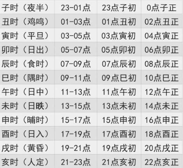
Could this be considered a truly authentic national style design?

However! The biggest highlight of this clock is actually its structural design…
Structural Design Description
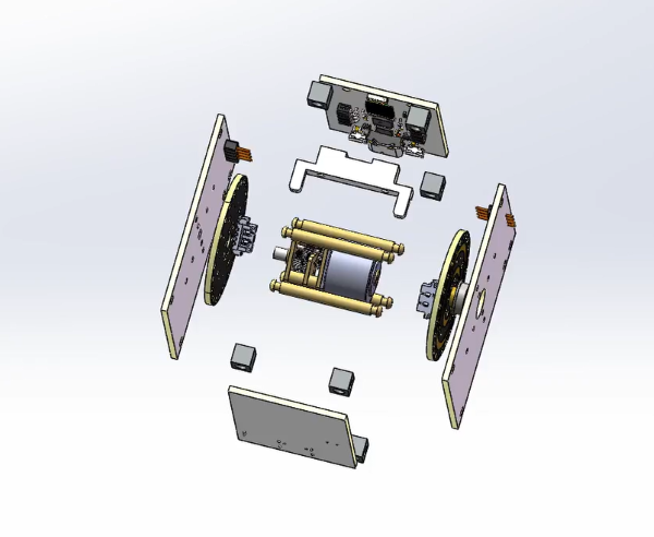
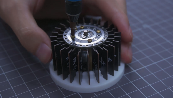
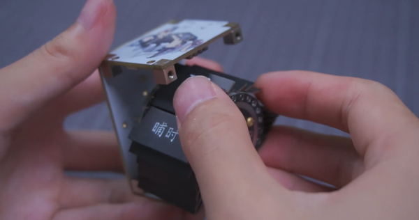
The structural feature of this clock is that it uses PCB as the frame, with a built-in motor, and the blade roller is designed as a slip ring, allowing the motor to rotate 360 degrees.
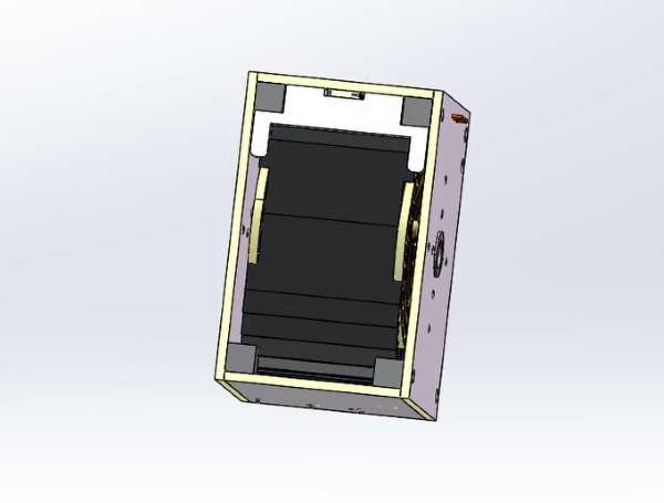 3D Model
This design has a high space utilization, making the structure more compact. However, it also has a higher cost, is not easy to assemble and maintain.
 Structural PartsInstallation Process
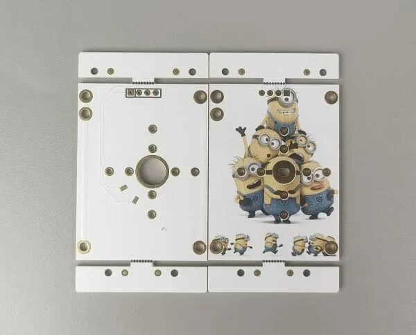
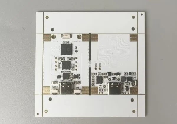
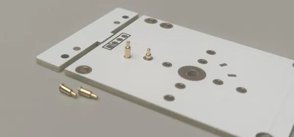
First, prepare all the PCBs and components.
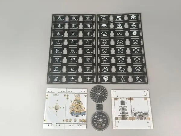 Blades, Main Control, Base Plate, Side Plates
Then, you can start the installation:
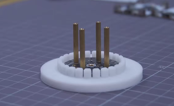
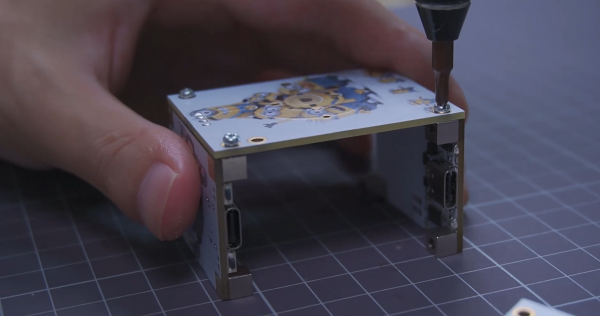

Scroll up and down to see more
 DIY Precautions
This section will explain: color silk screen printing, blade thickness, SMT precautions, and subsequent updates.
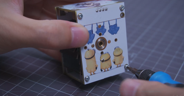
01Color Silk Screen Printing
If you want to replicate it, I personally recommend using color silk screen printing or double-sided panel printing. The color silk screen printing illustration is as follows:
If needed, you can check the color silk screen printing tutorial by clicking the image below:

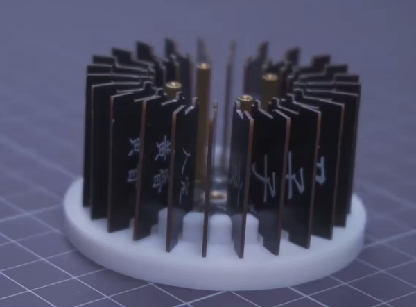
02Blades
The clock’s blade roller (slip ring) has 24/60 types.
For the 24-piece version, use PCB prototyping, with a thickness recommendation of0.8mm.
For the 60-piece version, use panel printing, with a thickness recommendation of ≤0.5mm.
03SMT
My main control and base plate have been SMT pasted at Jialichuang..
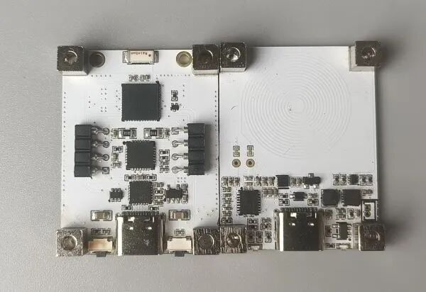
It should be noted that—the spring pin should not be pasted on the surface, it is best topass through from the back of the PCB.This waycan improve fault tolerance.
04Subsequent Updates
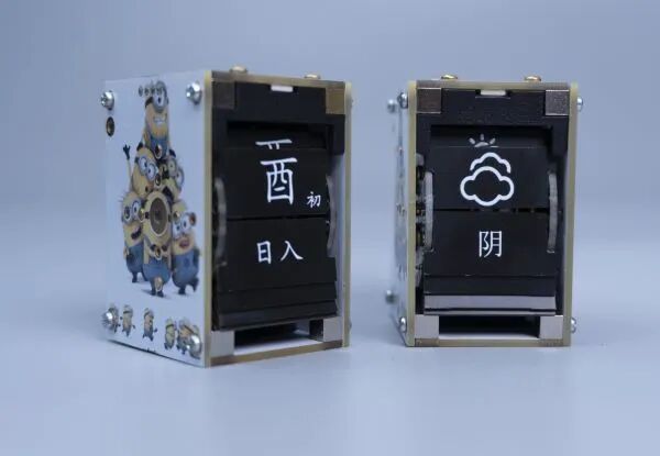
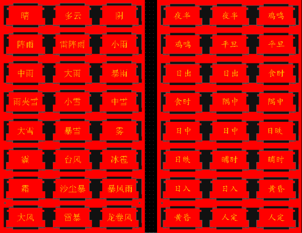
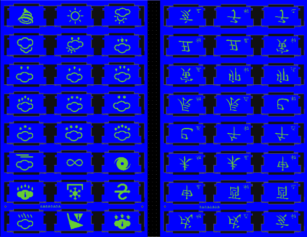
Currently, I have made two standalone versions, one displaying twenty-four solar terms and the other displaying weather.
But actually, this is all to pave the way for the dual-body version!
The dual-body clock looks like this, stay tuned~

Circuit Design Diagram
This is the schematic diagram of the main control, base plate, baffle, motor connection, and slip ring.
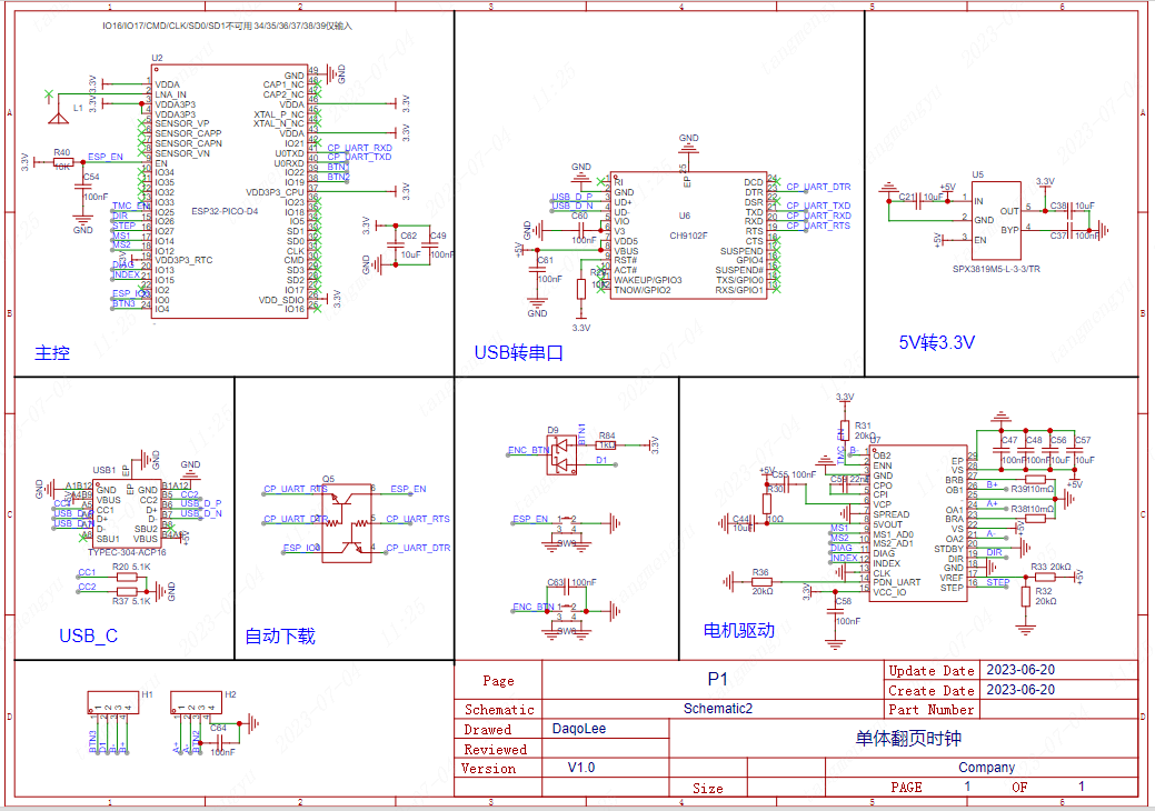 Main Control SchematicClick the image to enlarge
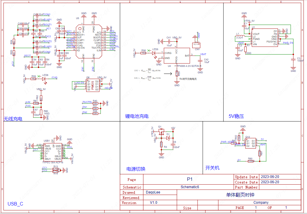 Base Plate Schematic
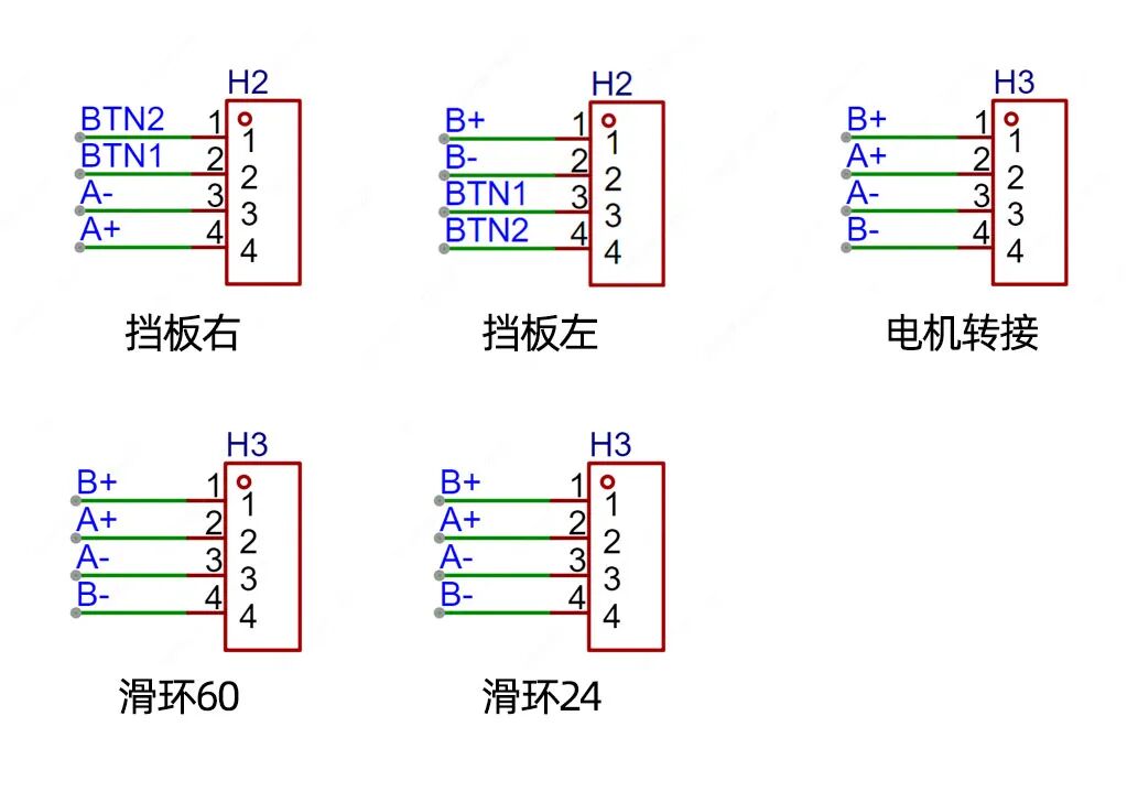 Other Schematic Diagrams
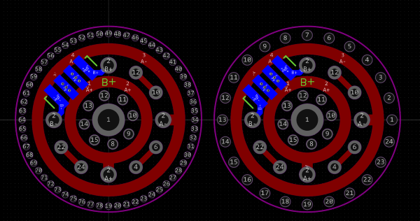
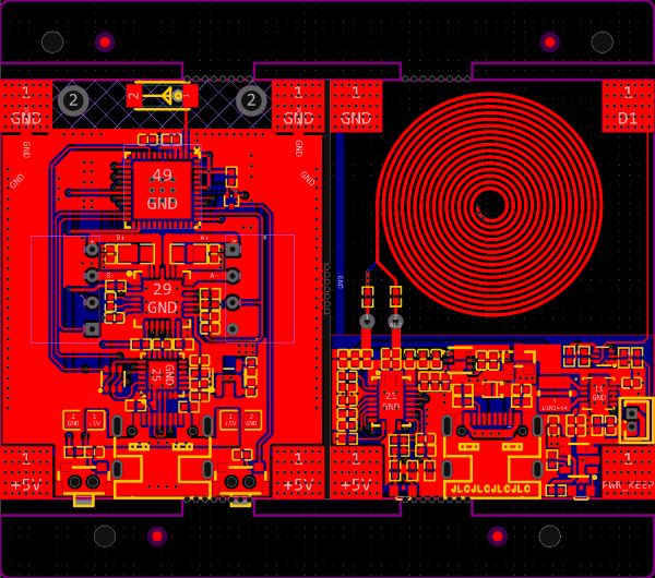
This is the PCB diagram of the blades, main control, base plate, and side plates.
Component Description
| Name | Parameter |
|---|---|
| Main Control Chip | ESP32-PICO-D4 |
| Motor Driver | TMC2209 |
| Lithium Battery Charger | TP4065 |
| 5V Voltage Regulator Chip | TPS63002 |
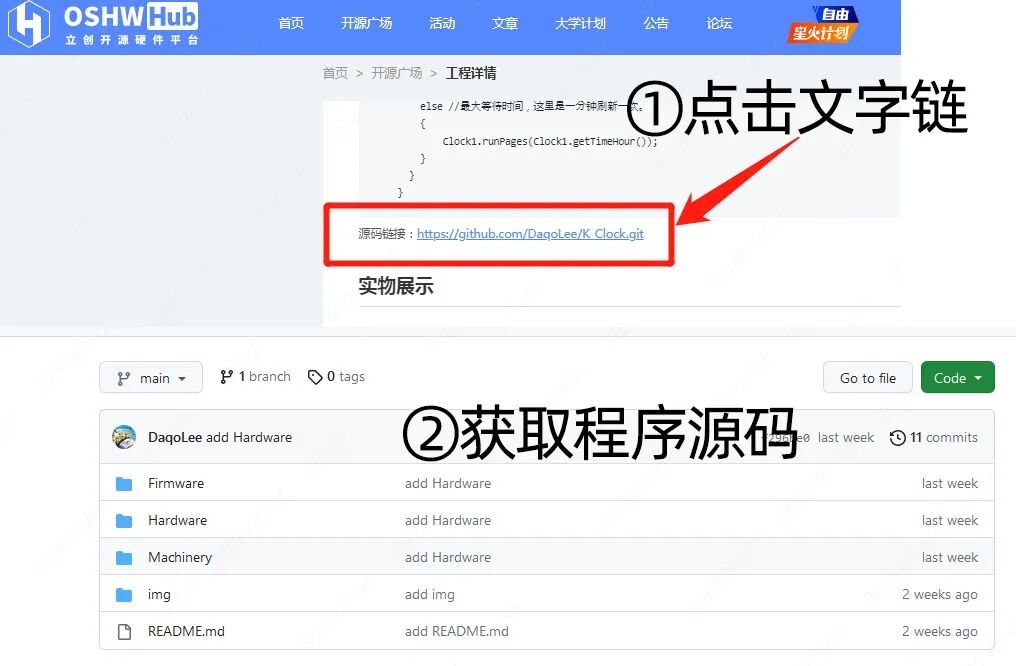
Source Code
There are many open-source codes for network clocks online, so the program part is also relatively simple, just modify the display part tocontrol the stepper motorand you’re good to go.
void ClockTask(void *arg)
{
    EventBits_t uxBits;
    Clock_config_t clockConfig = {
        .wifiConfig = {
            .sta = {
                "ssid", //ssid
                "password", // password
                .bssid_set = false,
            }
        },
        .ntpUrl = "ntp.aliyun.com",
        .userKey = "userKey", //心之天气userKey
        .location = "guangzhou",
        .powerPin = GPIO_NUM_4,
        .pages = 24, //叶片数
        .ntpInterval = 30,//网络校准时间间隔/分钟
        .speed = 2000, // 电机速度
        .compensation = 1000, //步进数误差补偿

        .stepperConfig = {
            .stepPin = 27,
            .dirPin = 26,
            .enPin = 25,
            .ms1Pin = 14, // 细分控制
            .ms2Pin = 12, //
            .timer_group = TIMER_GROUP_0,
            .timer_idx = TIMER_1,
            .miStep = MICROSTEP_16,  //电机驱动细分
            .stepAngle = 0.086//0.086 0.12 步进电机减速后的步进角
        }

    };
    Clock1.config(&clockConfig);
    Clock1.init();
    vTaskDelay(1000/portTICK_PERIOD_MS);
    Clock1.runPages(Clock1.getTimeHour());
    //Clock1.runPages(Clock1.getWeatherCode());
    while (1)
    {
        uxBits = xEventGroupWaitBits(
                       clock_event_group,
                       SNTP_BIT | BTNJUMP_BIT | BTNLONG_BIT,
                       pdTRUE,
                       pdFALSE,
                       60000/portTICK_PERIOD_MS );//60000/portTICK_PERIOD_MS portMAX_DELAY

        if(uxBits & SNTP_BIT)//时间校准事件
        {
            //Clock1.runPages(Clock1.getWeatherCode());
            //Clock1.runPages(Clock1.getTimeHour());
        }
        else if (uxBits & BTNJUMP_BIT)//按键短按跳变/松开
        {
            Clock1.runInf(200); //短按微调时间
        }
        else if (uxBits & BTNLONG_BIT)//按键长按
        {
            Clock1.powerOFF();//长按关机
        }
        else //最大等待时间,这里是一分钟刷新一次。
        {
            Clock1.runPages(Clock1.getTimeHour());
        }
    }
}
Video Demonstration
Open Source Material Download
If you need open source materials such as 【circuit, 3D printing, program, BOM list】, please click on “Read the original text” at the end of the article to obtain!
01Click to read the original text

02Get Circuit Source Files
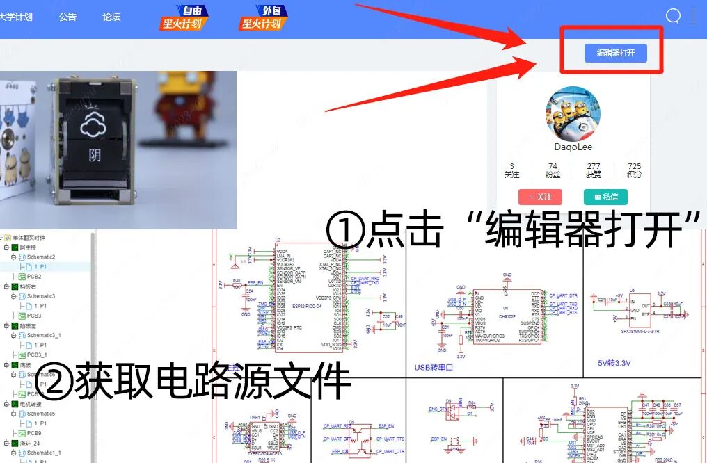
03Get Source Code
*This article is a reprint of user creations from the “Lichuang Open Source Hardware Platform”. If there is any infringement, please contact for deletion.
Give me a thumbs up if you like it! Click here to view the original project